
ACP-09CH25AEF - Air-conditioner Vivax - Free user manual and instructions
Find the device manual for free ACP-09CH25AEF Vivax in PDF.

| Product Type | Portable Air Conditioner (Monoblock) |
| Model | ACP-09CH25AEF |
| Brand | Vivax |
| Cooling Capacity | Approx. 9000 BTU/h (2.6 kW) |
| Heating Capacity | Heat pump type, approx. 9000 BTU/h |
| Operating Modes | Auto, Cool, Dry, Heat (heat pump), Fan |
| Fan Speeds | Low, Med, High, Auto |
| Temperature Setting Range | 17°C – 30°C (62°F – 88°F) |
| Timer | 24-hour programmable timer (Auto-on/off) |
| Airflow Control | Horizontal auto-swing louver |
| Remote Control | Included, with LCD display and Follow Me feature |
| Ionizer | Built-in (optional via remote) |
| Air Filter | Washable, upper and lower (clean every 2 weeks) |
| Water Drainage | Continuous drain (for dry/heat modes) or manual bottom tray drain |
| Exhaust Hose | Length adjustable: 30–120 cm, do not overbend |
| Window Kit | Included, fits vertical and horizontal windows |
| Power Supply | 220-240V ~ 50Hz (3-prong grounded plug) |
| Power Cord Length | Approx. 1.8 m |
| Weight | Approx. 25 kg |
| Dimensions (W x D x H) | Approx. 350 x 350 x 700 mm |
| Safety Features | Auto-restart, overheat protection, full tank indicator (P1) |
| Refrigerant | R32 (typical for model) |
| Noise Level | Approx. 50 dB (A) (typical) |
| Energy Efficiency | Class A or similar (check energy label) |
Frequently Asked Questions - ACP-09CH25AEF Vivax
User questions about ACP-09CH25AEF Vivax
0 question about this device. Answer the ones you know or ask your own.
Ask a new question about this device
Download the instructions for your Air-conditioner in PDF format for free! Find your manual ACP-09CH25AEF - Vivax and take your electronic device back in hand. On this page are published all the documents necessary for the use of your device. ACP-09CH25AEF by Vivax.
USER MANUAL ACP-09CH25AEF Vivax
natural_image
Symbol of a trash bin crossed with no visible text or labelsOdlaganje baterije u otpad

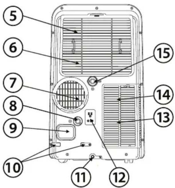
Prednja strana
1 ) Kontrolna ploča
2) Horizontalna rešetka za protok zraka (automatsko njihanje)
3) Kotači
4) Ručke za nošenje (s obje strane)
Stražnja strana
5 ) Gornji filter za zrak (iza rešetke)
6 ) Gornji ulaz za zrak
7) Izlaz za zrak
8) Odvod vode (samo za modele s grijaćom pumpom)
9 ) Utičnica za kabel za napajanje
10) Prostor za spremanje kabela za napajanje (koristi se samo kada se uređaj sprema)
11 ) Otvor na donjem spremniku za vodu
12) Utičnica za spremanje utikača (koristi se samo kada se uređaj sprema)
13 ) Donji filter za zrak (iza rešetke)
14 ) Donji ulaz zraka
15 ) Odvod vode
UPUTE ZA RUKOVANJE KONTROLNOM PLOČOM
Prije početka uporabe, dobro se upoznajte s kontrolnom pločom i daljinskim upravljačem i svim njihovim funkcijama, zatim aktivirajte željene funkcije putem njihovih simbola. Uređajem se može rukovati putem same kontrolne ploče ili daljinskim upravljačem.
KONTROLNA PLOČA KLIMA UREĐAJA
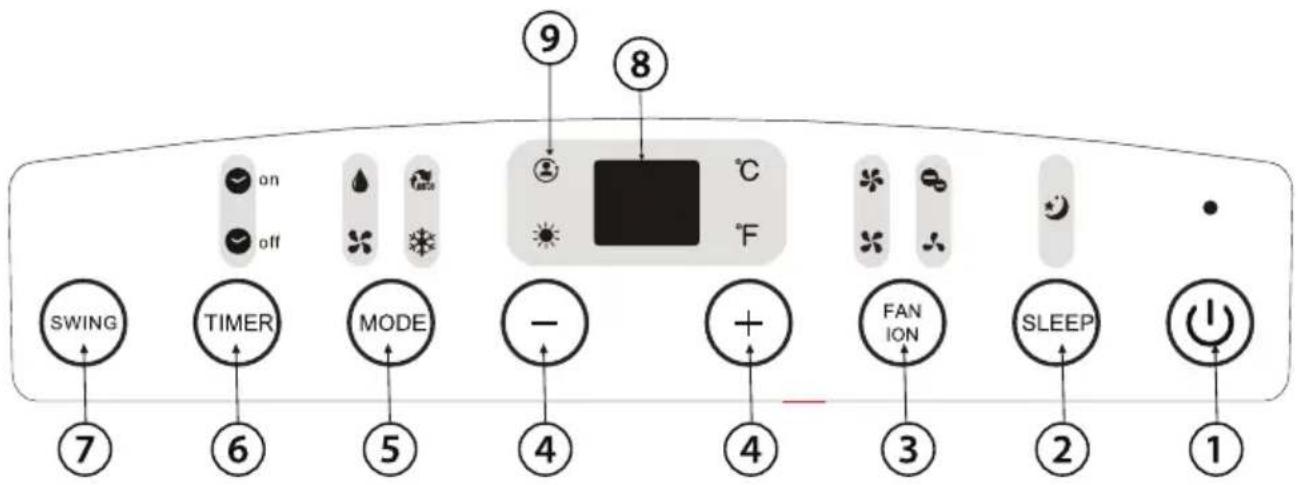
1) POWER tipka - služi za uključivanje i isključivanje uređaja
2) SLEEP tipka - služi za pokretanje SLEEP funkcije
3) FAN/ION tipka (ION je opcionalan) - kontrolira brzinu ventilatora.
natural_image
Diagram of a portable air conditioner unit with directional arrows indicating airflow or movement (no text or symbols)(A: 30 - 100 cm, B ≥ 30 cm)
- Klima uređaj treba biti postavljen na čvrstu i stabilnu podlogu kako bi se minimalizirala buka i vibracije. Za sigurno i čvrsto stavljanje, postavite uređaj na glatki i ravni pod, dovoljno čvrst da podržava uređaj
- Uređaj ima kotačiće koji mogu pomoći u postavljanju, no sigurni su za korištenje samo na glatkim i ravnim površinama. Budite oprezni prilikom korištenja kotačića na tepihu i ne pokušavajte prijeći s uređajem preko drugih predmeta
- Uređaj mora biti postavljen u doşegu uzemljene utičnice odgovarajućeg napona
- Pazite da ne bude prepreka protoku zraka oko uređaja
- Osigurajte 30cm-100cm prostora od zida za efikasni rad uređaja.
Postavljanje na prozor
natural_image
Simple line drawing of a container with two downward arrows and an internal arrow, no text or symbols present.
natural_image
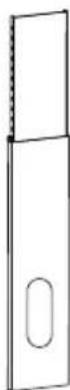
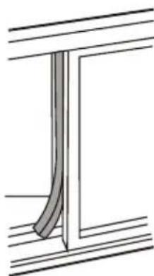
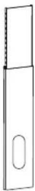
Line drawing of a portable air conditioner unit with cooling fins and a hanging handle (no text or symbols)Vaš pribor za postavljanje na prozor je dizajniran da odgovara većini standardnih „vertikalnih“ i „horizontalnih“ prozora. Usprkos tome, možda će te morati improvizirati/modificirati neke dijelove procedure postavljanja za neke vrste prozora. Molimo pogledajte sliku kako biste vidjeli minimalne i maksimalne dimenzije prozora. Pribor za postavljanje na prozor može biti učvršćen vijkom (slika).
natural_image
Simple line drawing of a door with arrows indicating direction, no text or symbols present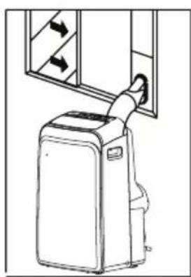
natural_image
Line drawing of a portable air conditioner unit with airflow direction arrows (no text or symbols)Bilješka: Ako je prozor uži od spomenute minimalne dužine pribora, možete njegovu dužinu prilagoditi rezanjem. Nikad nemojte prerezati pribor za postavljanje na prozor kroz otvor u njemu.
UPUTE ZA POSTAVLJANJE (opcionalno)
Postavljanje na dvokrilnom prozoru
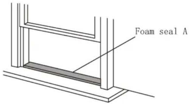
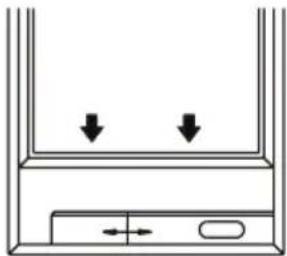
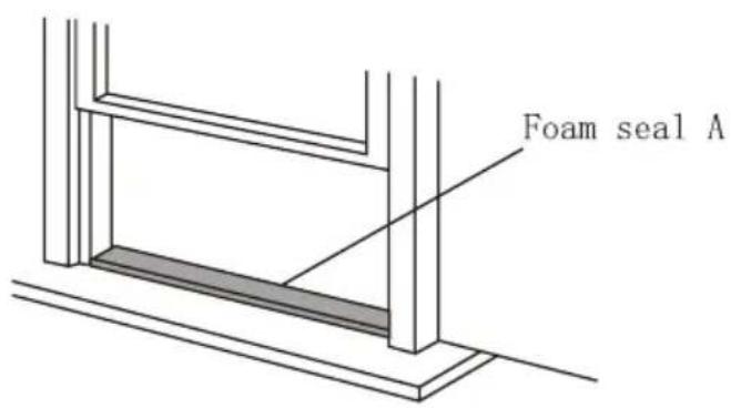
1) Izrežite pjenu za brtvljenje ("foam seal A") na ispravnu dužinu i pričvrstite ju na podnožje prozora

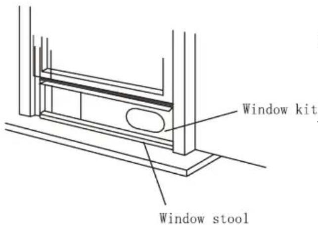
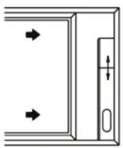
2) Pričvrstite pribor za postavljanje (window kit) na prozor na podnožje prozora (window stool). Podesite dužinu pribora ovisno o širini prozora, skratite prilagodivi pribor ako je širina prozora ispod 67, 3 cm (Tip I) ili 56,1 cm (Tip II). Otvorite krila prozora i postavite pribor na podnožje prozora.
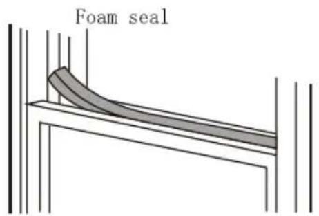
3) Izrežite pjenu za brtvljenje na ispravnu dužinu i pričvrstite ju na vrh prozora.
4) Dobro zatvorite krila prozora.
5) Izrežite pjenu za brtvljenje na ispravnu dužinu i zatvorite otvore između dvaju krila prozora.
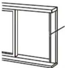
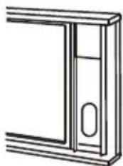
Window panel

natural_image
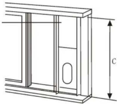
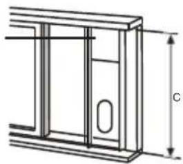
Technical line drawing of a window frame structure with dimension label 'C' (no text or symbols beyond the label)
natural_image
Line drawing of a door frame with a handle and oval opening (no text or symbols)Foam seal
natural_image
Pure technical line drawing of a structural component with no text or symbols1) Izrežite pjenu za brtvljenje ("foam seal") na ispravnu dužinu i pričvrstite ju na okvir prozora.
2) Pričvrstite pribor za postavljanje na prozor na podnožje prozora. Podesite dužinu pribora ovisno o širini prozora, skratite prilagodivi pribor ako je širina prozora ispod 67, 3 cm (Tip I) ili 56,1 cm (Tip II). Otvorite krila prozora i postavite pribor na podnožje prozora.
3) Izrežite pjenu za brtvljenje na ispravnu dužinu i pričvrstite ju na vrh prozora.
4) Dobro zatvorite krilo prozora.
5) Izrežite pjenu za brtvljenje na ispravnu dužinu i zatvorite otvore između krila prozora i okvira.
Bilješka: Sve slike su samo u svrhu objašnjavanja, vaš uređaj može biti malo drugačiji. Presudan je stvarni oblik vašeg uređaja.

natural_image
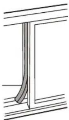
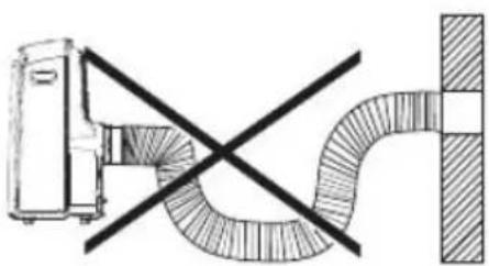
Diagram showing a vehicle and a curved pipe with diagonal lines, no text or symbols presentVAŽNO: NEMOJTE PREVIŠE SAVITI ISPUŠNU CIJEV
OPREZ: Pobrinite se da ne bude prepreka protoku zraka u rasponu od 500 mm oko izlaza zraka iz ispušne cijevi da bi ispušni sustav mogao dobro raditi.
Odvodenje vode:

- Za vrijeme SUŠENJA, odstranite čep iz gornjeg odvoda za vodu na stražnjem dijelu uređaja, ovisno o modelu postavite adapter za odvodnu cijev ili samo odvodnu cijev (odvodnu cijev morate sami kupiti). Otvoreni kraj odvodne cijevi stavite u spremnik za vodu na dnu uređaja.

- Za vrijeme GRIJANJA toplinskom pumpom, odstranite čepizgornjeg odvoda za vodu na stražnjem dijelu uređaja, ovisno o modelu postavite adapter za odvodnu cijev ili samo odvodnu cijev (odvodnu cijev morate sami kupiti). Otvoreni kraj odvodne cijevi stavite u spremnik za vodu na dnu uređaja. Bilješka: Pobrinite se da cijev bude dobro pričvršćena tako da ne bude curenja. Usmjerite cijev prema odvodu, pritom pazeći da ne bude prepreka toku vode i da je cijev usmjerena prema dolje, a ne prema gore.

natural_image
Line drawing of a large air conditioner unit with cooling fans and ventilation slots (no text or symbols)- Kada razina vode u spremniku za vodu dosegne predodređenu razinu, uređaj zvučno signalizira 8 puta i na kontrolnoj ploči se pojavi „P1“. U tom trenutku proces hlađenja/grijanja i sušenja zraka će se automatski zaustaviti, no ventilator će nastaviti raditi (to je normalno). Oprezno premjestite uređaj na lokaciju za odvod vode, izvadite čep iz spremnika za vodu i pustite vodu da iscuri. Vratite čep i ponovo pokrenite uređaj dok simbol „P1“ ne nestane. Ako se greška ponavlja, pozovite servisera.


Važno:
1) Pobrinite se da iskopčate uređaj iz struje prije čišćenja ili servisa
2) Nemojte koristiti benzin, razrjeđivač ili druge kemikalije za čišćenje uređaja
3) Nemojte prati uređaj direktno ispod mlaza vode. Može uzrokovati rizik od strujnog udara.
4) Ako je kabel za napajanje oštećen, treba ga popraviti proizvođač ili ovlašteni stručnjak
Filter za zrak
natural_image
Symbol of a trash bin crossed with no visible text or labels
Prednja strana
1) Kontrolna tabla
2) Horizontalna rešetka za protok vazduha (automatsko njihanje)
3) Točkovi
4 ) Ručke za nošenje (s obe strane)
Stražnja strana
natural_image
Diagram of a portable air conditioner unit with directional arrows indicating airflow or movement (no text or symbols present)natural_image
Simple line drawing of a container with two downward arrows and an internal arrow, no text or symbols present.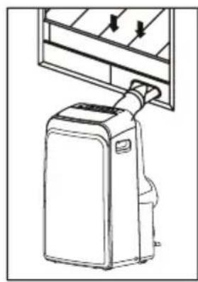
natural_image
Line drawing of a portable air conditioner unit with cooling fins and a handle (no text or symbols)Vaš pribor za postavljanje na prozor je dizajniran da odgovara većini standardnih vertikalnih i horizontalnih prozora. Usprkos tome, možda ćete morati da improvizujete/modifikujete neke delove procedure postavljanja za neke vrste prozora. Pogledajte sliku kako biste videli minimalne i maksimalne dimenzije prozora. Pribor za postavljanje na prozor može biti učvršćen zavrtnjem. (slika)
natural_image
Simple line drawing of a door with arrows indicating direction and a vertical dimension line (no text or symbols)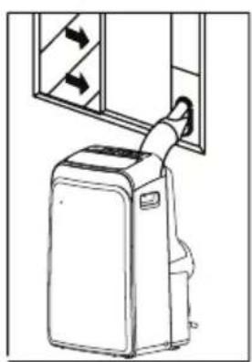
natural_image
Line drawing of a portable air conditioner unit with airflow arrows (no text or symbols)BELEŠKA: Ako je prozor uži od navedene minimalne dužine pribora, možete njegovu dužinu da prilagodite rezanjem. Nikad nemojte prerezati pribor za postavljanje na prozor kroz otvor u njemu.
UPUTSTVA ZA POSTAVLJANJE (opciono)
Postavljanje na dvokrilnom prozoru

1) Izrežite penu za zaptivanje ("foam seal") na pravilnu dužinu i pričvrstite ju na okvir prozora.
Window panel
natural_image
Technical line drawing of a structural frame with dimension label 'C' (no text or symbols beyond the label)2) Pričvrstite pribor za postavljanje na prozor na podnožje prozora. Podesite dužinu pribora ovisno o širini prozora, skratite prilagodivi pribor ako je širina prozora ispod 67.3 cm (Tip I) ili 56.1 cm (Tip II). Otvorite krila prozora i postavite pribor na podnožje prozora.

natural_image
Line drawing of a door frame with a handle and oval opening (no text or symbols)3) Izrežite penu za zaptivanje na pravilnu dužinu i pričvrstite je na vrh prozora. 4) Dobro zatvorite krilo prozora.
Foam seal
natural_image
Pure technical line drawing of a structural component without any text, numbers, or symbols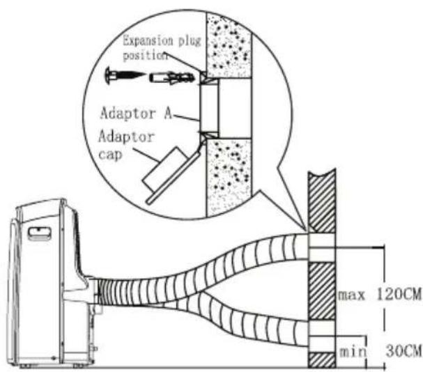
1) Postavite adapter B i adapter A na izduvnu cev kako je pokazano na slici. Proučite prethodne strane za uputstva o postavljanju na prozor.
2) Gurnite izduvnu cev u njeno ležište na izlazu za vazduh na vašem klima uređaju. Učvrstite je tako da kukice na izduvnoj cevi stavite u za njih predviđene ležajeve i pomerite cev u smeru koji pokazuju strelice na slici.
Izduvnu cev moguće je postaviti u zid. (Osim kod uređaja koji u priboru nemaju adapter A, tiplove i drvene zavrtnje)
1) Pripremite rupu u zidu. Postavite zidni izduvni adapter A na zid (spolja) korištenjem 4 tipla i drvenih vijaka. Pobrinite se da dobro učvrstite.
2) Pričvrstite izduvnu cev na zidni izduvni adapter A.
Beleška: Pokrijte rupu poklopcem adaptera kada uređaj nije u upotrebi. Izduvna cev može biti skraćena ili produžena u zavisnosti od potrebe ali poželjno je da bude što kraća
natural_image
Diagram showing a vehicle and a curved pipe with diagonal lines, no text or symbols presentVAŽNO:
NEMOJTE PREVIŠE DA SAVIJETE IZDUVNU CEV
OPREZ:
- Za vreme SUŠENJA, odstranite čep iz gornjeg odvoda za vodu na stražnjem delu uređaja, u zavisnosti od modela postavite adapter za odvodnu cev ili samo odvodnu cev (odvodnu cev (crevo) morate sami da kupite). Otvoreni kraj odvodne cevi stavite u posudu za vodu na dnu uređaja.

- Za vreme GREJANJA toplotnom pumpom, odstranite čep iz gornjeg odvoda za vodu na stražnjem delu uređaja, u zavisnosti od modela postavite adapter za odvodnu cev ili samo odvodnu cev (odvodnu cev morate sami da kupite). Otvoreni kraj odvodne cevi stavite u posudu za vodu na dnu uređaja.
BELEŠKA: Pobrinite se da cev bude dobro pričvršćena tako da ne bude curenja. Usmerite cev prema odvodu, pritom pazeći da ne bude prepreka toku vode i da je cev usmerena prema dole a ne prema gore.

natural_image
Line drawing of a large air conditioner unit with cooling fans and ventilation slots (no text or symbols)- Kada voda u posudi za vodu dosegne predviđeni nivo, uređaj zvučno signalizira 8 puta i na kontrolnoj tabli se pojavi „P1“. U tom trenutku, automatski se zaustavlja proces hlađenja/grejanja i sušenja vazduha ali ventilator će nastaviti da radi (to je normalno). Oprezno premestite uređaj na lokaciju za odvod vode, izvadite čep iz posude za vodu i pustite vodu da iscuri. Vratite čep i ponovo pokrenite uređaj dok simbol „P1“ ne nestane. Ako se „P1“ ponavlja, pozovite servisera.
BELEŠKA: Proverite jeste li vratili čep u posudu za vodu pre ponovnog upotrebe uređaja.
BRIGA I ODRŽAVANJE
Važno:
1) Pobrinite se da isključite uređaj iz struje pre čišćenja ili servisa
2) Nemojte upotrebljavati benzin, razređivač ili druge hemikalije za čišćenje uređaja
3) Nemojte prati uređaj ispod mlaza vode. To predstavlja rizik od mogućeg strujnog udara.
4) Ako je kabl za napajanje oštećen, treba da ga popravi proizvođač ili ovlašćeni stručnjak
Filtar za vazduh
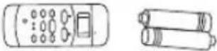
Daljinski upravljač koristi dve alkalne suve baterije (R03/LR03X2) smeštene sa donje strane i zatvorene poklopcem.
(1) Pritiskom i povlačenjem uklonite poklopac.
(2) Uklonite stare i umetnite nove baterije pazeći pritom na polove baterija ((+) i (-)).
(3) Vratite poklopac na mesto.
NAPOMENA: Nakon uklanjanja baterija daljinski upravljač briše sve programe. Nakon umetanja novih baterija daljinski upravljač treba nanovo programirati.
OPREZ
- Ne mešajte stare i nove baterije ili različite tipove baterija.
- Ne ostavljajte baterije u daljinskom upravljaču ukoliko ga ne nameravate koristiti 2 ili 3 meseca.
- Baterije odložite u posebne odlagače koji se mogu pronaći u prodavnicama elektro opreme.
Specifikacije daljinskog upravljača
| Model | ACP-09PT25AEH, ACP-12PT35AEH |
| Radni napon | 3.0V (Alkalne baterije R03/LR03 X2) |
| Najniži napon emitovanjaCPU signala | 2.0V |
| Domet signala | 8m (prilikom upotrebe napona od 3.0V, postaje 11m) |
| Radna okolina | -5°C ~ 60°C |
NAPOMENA:
Prikaz postavljene temperature:
Funkcije
- Načini rada: AUTOMATSKI, HLAĐENJE, SUŠENJE, GREJANJE (samo modeli sa grejanjem) i VENTILATORSKI RAD.
- Funkcija postavljanja timera u vremenskom rasponu do 24 sata.
- Raspon postavljanja unutrašnje temperature: 17°C\~30°C
- U potpunosti funkcionalan LC ekran
- Pozadinsko osvetljenje ekrana.
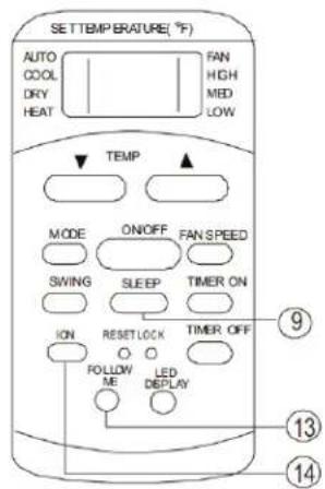
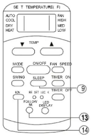
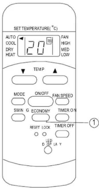
⑨ taster ECONOMY(SLEEP)
Odaberite ovu funkciju tokom spavanja. Ona održava najudobniju temperaturu i štedi energiju. Ova funkcija je raspoloživa samo prilikom hlađenja, grejanja ili automatskog rada.
⑫ Taster LED Display
Pritisnite ovaj taster za gašenje pozadinskog osvetljenja ekrana te je ponovo pritisnite kako biste uključili osvetljenje.
13 Taster FOLLOW ME
- Pritisnite ovaj taster za aktivaciju funkcije FOLLOW ME.
- Kada je funkcija Follow Me aktivna na daljinskom upravljaču se prikazuje temperatura na njegovom mestu. Daljinski upravljač će slati ovaj signal klima uređaju svaka tri minuta, sve dok ponovo ne pritisnete taster Follow Me.
- Funkcija Follow Me nije raspoloživa tokom sušenja i ventilatorskog rada.
- Promena načina rada ili isključenje klima uređaja će automatski poništiti ovu funkciju.
14 Taster ION
Pritiskom ovog tastera aktivira se generator iona koji pomaže u otklanjanju grinja i nečistoća iz vazduha.
Indikatori na ekranu
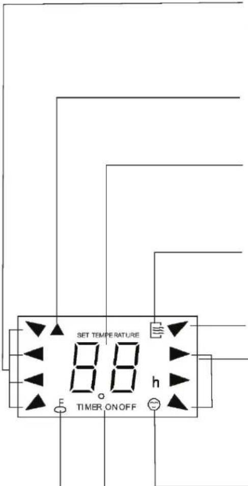
Indikator načina rada
Prikazuje trenutni način rada, uključujući automatski rad, hlađenje, sušenje, grejanje (modeli sa grejanjem i hlađenjem) i ventilatorski način rada.
Indikator odašiljanja
natural_image
Symbol of a trash bin crossed with no visible text or labels
Divlje odbacivanje otpada u šumama i krajolicima može ugroziti vaše zdravlje ako opasne materije procure u podzemne vode i pronađu svoj put u prehrambeni lanac.
MJERE OPREZA
Sigurnosna pravila
Kako bi se spriječila povreda korisnika ili drugih ljudi te materijalna šteta, potrebno je slijediti sljedeća uputstva. Neispravna upotreba uslijed ignorisanja ovih uputstava može uzrokovati povredu ili štetu.
UVIJEK RADITE

Prednja strana
1) Kontrolna ploča
2) Horizontalna rešetka za protok vazduha (automatsko njihanje)
3) Točkovi
4) Ručke za nošenje (s obje strane)
Zadnja strana
natural_image
Diagram of a portable air conditioner unit with directional arrows indicating airflow or movement (no text or symbols)(A: 30 -100 cm, B ≥ 30 cm)
natural_image
Simple line drawing of a container with two downward arrows and an internal arrow, no text or symbols present.
natural_image
Line drawing of a portable air conditioner unit with cooling fins and a handle (no text or symbols)Vaš pribor za postavljanje na prozor je dizajniran da odgovara većini standardnih „vertikalnih“ i „horizontalnih“ prozora. Uprkos tome, možda ćete morati improvizirati/modifikovati neke djelove procedure postavljanja za neke vrste prozora. Molimo pogledajte slike kako biste vidjeli minimalne i maksimalne dimenzije prozora. Pribor za postavljanje na prozor može biti učvršćen zavrtnjem.

natural_image
Simple line drawing of a door with arrows indicating direction, no text or symbols present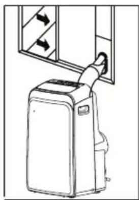
natural_image
Line drawing of a portable air conditioner unit with airflow arrows (no text or symbols)BILJEŠKA: Ako je prozor uži od spomenute minimalne dužine pribora, možete njegovu dužinu prilagoditi rezanjem. Nikad nemojte prerezati pribor za postavljanje na prozor kroz otvor u njemu.

UPUTSTVA ZA POSTAVLJANJE (opcionalno)
Postavljanje na dvokrilnom prozoru
1) Izrežite pjenu za zaptivanje ("foam seal A") na ispravnu dužinu i pričvrstite je na podnožje prozora.

2) Pričvrstite pribor za postavljanje na prozor na podnožje prozora. Podesite dužinu pribora u zavisnosti od širine prozora, skratite prilagodljivi pribor ako je širina prozora ispod 67, 3 cm (Tip I) ili 56,1 cm (Tip II). Otvorite krila prozora i postavite pribor na podnožje prozora.

3) Izrežite pjenu za zaptivanje na ispravnu dužinu i pričvrstite je na vrh prozora, pokazano na slici.
4 ) Dobro zatvorite krila prozora.

5) Izrežite pjenu za zaptivanje na ispravnu dužinu i zatvorite otvore između dva krila prozora.
Window panel

natural_image
Technical line drawing of a window frame structure with height dimension labeled 'C' (no text or symbols beyond the label)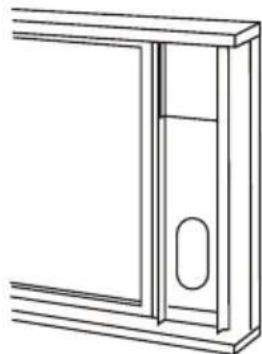
natural_image
Line drawing of a door frame with a handle and oval opening (no text or symbols)Foam seal

natural_image
Pure technical line drawing of a structural component with no text or symbols1) Izrežite pjenu za zaptivanje ("foam seal") na ispravnu dužinu i pričvrstite je na okvir prozora.
2) Pričvrstite pribor za postavljanje na prozor na podnožje prozora. Podesite dužinu pribora u zavisnosti od širine prozora, skratite prilagodljivi pribor ako je širina prozora ispod 7, 3 cm (Tip I) ili 56,1 cm (Tip II).
Otvorite krila prozora i postavite pribor na podnožje prozora.
3) Izrežite pjenu za zaptivanje na ispravnu dužinu i pričvrstite je na vrh prozora, pokazano na slici.
4 ) Dobro zatvorite krilo prozora.
5) Izrežite pjenu za zaptivanje na ispravnu dužinu i zatvorite otvore između krila prozora i okvira.

natural_image
Diagram showing a vehicle and a curved pipe with diagonal lines, no text or symbols presentVAŽNO:
NEMOJTE PREVIŠE SAVITI IZDUVNU CIJEV
OPREZ:
Pobrinite se da ne bude prepreka protoku vazduha u rasponu od 500mm oko izlaza vazduha iz izduvne cijevi da bi izduvni sistem mogao dobro raditi.
Odvodenje vode:


natural_image
Line drawing of a large air conditioner unit with cooling fans and ventilation slots (no text or symbols)- Za vrijeme SUŠENJA, odstranite čep iz gornjeg odvoda za vodu na zadnjem dijelu uređaja, u zavisnosti od modela postavite adapter za odvodnu cijev ili samo odvodnu cijev (odvodnu cijev morate sami kupiti). Otvoreni kraj odvodne cijevi stavite u posudu za vodu na dnu uređaja.
- Za vrijeme GRIJANJA toplotnom pumpom, odstranite čep iz gornjeg odvoda za vodu na zadnjem dijelu uređaja, u zavisnosti od modela postavite adapter za odvodnu cijev ili samo odvodnu cijev (odvodnu cijev morate sami kupiti). Otvoreni kraj odvodne cijevi stavite u posudu za vodu na dnu uređaja.
BILJEŠKA: Pobrinite se da cijev bude dobro pričvršćena tako da ne bude curenja. Usmjerite cijev prema odvodu, pritom pazeći da ne bude prepreka toku vode i da je cijev usmjerena prema dolje a ne prema gore.
- Kada nivo vode u posudi za vodu dosegne predodređeni nivo, uređaj zvučno signalizira 8 puta i na kontrolnoj ploči se pojavi „P1“. U tom trenutku proces hlađenja/grijanja i sušenja vazduha će se automatski zaustaviti, no ventilator će nastaviti raditi (to je normalno). Oprezno premjestite uređaj na lokaciju za odvod vode, izvadite čep iz posude za vodu i pustite vodu da iscuri. Vratite čep i ponovo pokrenite uređaj dok simbol „P1“ ne nestane. Ako se greška ponavlja, pozovite servisera.
Upper fil (take out)
Remove the screw, then take the lower filter out.

Upper fil (install)
Install the low filter by using the screw.

natural_image
Technical line drawing of an air conditioning unit with cooling fan and fan blades (no text or symbols)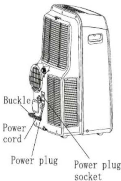
Važno:
1) Pobrinite se da iskopčate uređaj iz struje prije čišćenja ili servisa
2) Nemojte koristiti benzin, razrjeđivač ili druge hemikalije za čišćenje uređaja
3) Nemojte prati uređaj direktno ispod mlaza vode. Može uzrokovati rizik od strujnog udara.
4) Ako je kabl za napajanje oštećen, treba ga popraviti proizvođač ili ovlašćeni stručnjak
Filter za vazduh
Čistite filter za vazduh barem jednom svake 2 sedmice kako biste spriječili pogoršanje rada ventilatora zbog prašine
Odstranjivanje
natural_image
Symbol of a trash bin crossed with no visible text or labels
Предна страна
natural_image
Line drawing of a portable air conditioner unit with airflow indicators (no text or symbols)natural_image
Diagram of a portable air conditioner unit with directional arrows indicating airflow or movement (no text or symbols)natural_image
Simple line drawing of a container with two downward arrows and an internal arrow, no text or symbols present.
natural_image
Line drawing of a portable air conditioner unit with cooling fins and a handle (no text or symbols)natural_image
Simple line drawing of a door with arrows indicating direction, no text or symbols present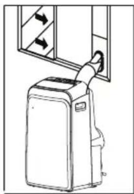
natural_image
Line drawing of a portable air conditioner unit with airflow arrows (no text or symbols)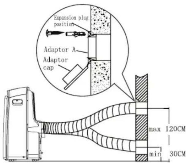
natural_image
Diagram showing a vehicle and a curved pipe with diagonal lines, no text or symbols presentВАЖНО:
НЕМОЈТЕ ПРЕМНОГУ ДА ЈА ВИКТКАТЕ ИСПУШНАТА ЦЕВКА
ВНИМАНИЕ:

natural_image
Line drawing of a large air conditioner unit with cooling fans and ventilation slots (no text or symbols)Upper filt (take out)
Remove the screw, then take the lower filter out.
Upper fil (install)
natural_image
Technical line drawing of an air conditioner unit with cooling fan and ventilation slots (no text or labels)Install the low filter by using the screw.
Важно:
natural_image
Symbol of a trash bin crossed with no visible text or labels

Pjesa e përparme
natural_image
Line drawing of a portable air conditioner unit with cooling fan and ventilation slots (no text or symbols)natural_image
Diagram of a portable air conditioner unit with directional arrows indicating airflow or movement (no text or symbols)natural_image
Simple line drawing of a container with two downward arrows and an internal arrow, no text or symbols present.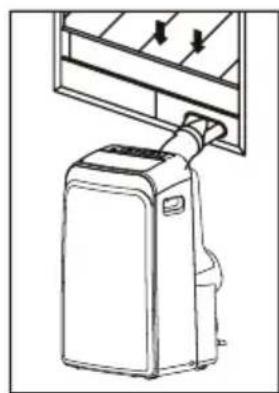
natural_image
Line drawing of a portable air conditioner unit with cooling fins and a hanging handle (no text or symbols)natural_image
Simple line drawing of a door with arrows indicating direction, no text or symbols present
natural_image
Line drawing of a portable air conditioner unit with airflow arrows (no text or symbols)1) E vendosni shkumen per mbyllje ne hapesire te duhur dhe bashkangjiten ne bazen e dritares
2) Bashkangjitni paisjet per vendosje ne dritare sipas hapesires ne dritare. Percaktoni gjatesine e paisjes varesisht prej gjeresise se dritares,shkurtojeni paisjen zgajtese nese gjeresia e dritares eshte me e vogel se 67,3 cm (Tip I) ose 56,1 cm (Tip II)

natural_image
Pure technical line drawing of a structural frame or panel (no text or symbols)Foam seal A
1) E vendosni shkumen per mbyllje ne hapesire te duhur dhe bashkangjiten ne bazen e dritares
Window panel
natural_image
Technical line drawing of a structural frame with a vertical dimension labeled 'C' (no text or symbols beyond the label)2) Bashkangjitni paisjet per vendosje ne dritare sipas hapesires ne dritare. Percaktoni gjatesine e paisjes varesisht prej gjeresise se dritares,shkurtojeni paisjen zgajtese nese gjeresia e dritares eshte me e vogel se 67, 3 cm (Tip I) ose 56,1 cm (Tip II)
natural_image
Line drawing of a door frame with a handle and oval opening (no text or symbols)natural_image
Pure technical line drawing of a structural component without any text, numbers, or symbols4) Mbylleni mire kendet e dritareve
1) Vendosni adapterin B dhe adapterin A ne gypin thithes siç eshte e treguar ne foton. Lexoni faqet paraprake sipas menyres se vendosje ne dritare
natural_image
Diagram showing a vehicle and a curved pipe with diagonal lines, no text or symbols presentE RËNDËSISHME:
NUK BËN TË PËRKULENI MBI TUBIN E SHKARKIMIT (shiko)
KUJDES:

natural_image
Line drawing of a large air conditioner unit with cooling fans and ventilation slots (no text or symbols)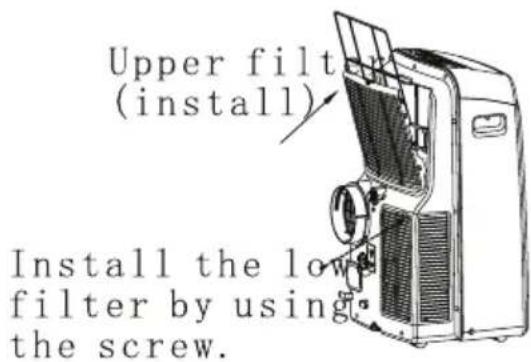

FUNKCJE KLIMATYZATORA
natural_image
Symbol of a trash bin crossed with no visible text or numbersRys. 1
Tyt
Rys. 2
PANEL OPERACYJNY KLIMATYZATORA
Rys. 3
natural_image
Diagram of a mechanical device with a cylindrical shaft and textured body, labeled 'Rys. 20' (no readable text or symbols beyond label)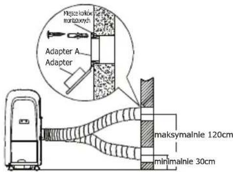
natural_image
Diagram showing a device connected to a curved pipe with a diagonal line crossing through it (no text or symbols present)Rys. 22
natural_image
Diagram of a mechanical assembly showing a housing, battery pack, and internal components (no text or labels)
UWAGA!
14, 15,16,17, 18, 19, 20, 21, 22, 23 and 24.
10, 11, 12, 13,
PRZYKŁAD TRYBU TIMER ON:
TRYB MIESZANY
natural_image
Symbol of a trash bin crossed with no visible text or labels
Prednja stran
1 ) Kontrolna plošča
2) Horizontalna rešetka za pretok zraka (avtomatsko nihanje)
3 ) Kolesa
4) Ročke za prenašanje (z obeh strani)
Hrbtna stran
natural_image
Line drawing of a portable air conditioner unit with airflow indicators (no text or symbols)natural_image
Diagram of a refrigerant system with directional arrows indicating airflow or movement, showing no text or symbols.natural_image
Simple line drawing of a container with two downward arrows and an internal arrow, no text or symbols present.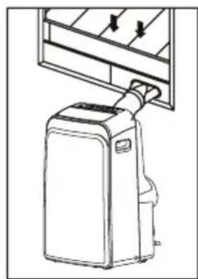
natural_image
Line drawing of a portable air conditioner unit with cooling fins and a hanging handle (no text or symbols)natural_image
Simple line drawing of a door with arrows indicating direction, no text or symbols present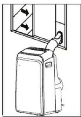
natural_image
Line drawing of a portable air conditioner unit with airflow direction arrows (no text or symbols)2) Pričvrstite okenski komplet na podnože okna. Prilagodite dolžino kompleta na širino okna, krajšajte ga će je širina okna pod 67, 3 cm (Tip I) ili 56,1 cm (Tip II).
natural_image
Line drawing of a door frame with an oval cutout and horizontal bracing (no text or symbols)natural_image
Diagram showing a vehicle and a curved pipe with diagonal lines, no text or symbols presentVAŽNO:
IZPUŠNE CEVI NE ZVIJAJTE PREVEČ
PREVIDNO:

natural_image
Line drawing of a large air conditioner unit with cooling fans and ventilation slots (no text or symbols)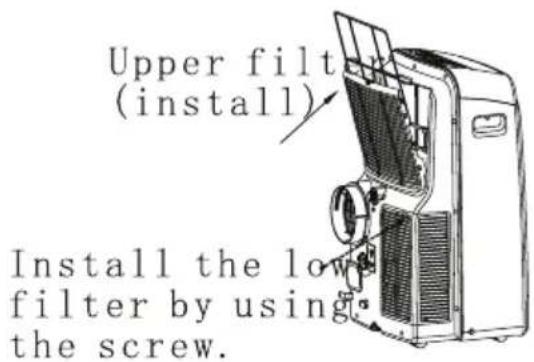
Važno:
Electronic control operating instructions
OPERATING INSTRUCTIONS
Operating instructions
INSTALLATION INSTRUCTIONS
Location
Window kit installation
Exhaust hose installation
Water drainage
CARE AND MAINTENANCE
Care and maintenance
TROUBLESHOOTING TIPS
Trouble shooting
NOTE
The rating data indicated on the energy label is based on the testing condition of installing the un-extended air exhaust duct without adaptor A & B (The duct and the adaptor A & B are listed in the accessories chart of the Instruction Manual).
When using this air conditioner in the European countries, the following information must be followed:
DISPOSAL: Do not dispose this product as unsorted municipal waste. Collection of such waste separately for special treatment is necessary.
It is prohibited to dispose of this appliance in domestic household waste.
For disposal, there are several possibilities:
A) The municipality has established collection systems, where electronic waste can be disposed of at least free of charge to the user.
B) When buying a new product, the retailer will take back the old product at least free of charge.
C) The manufacture will take back the old appliance for disposal at least free of charge to the user.
D) As old products contain valuable resources, they can be sold to scrap metal dealers.
Wild disposal of waste in forests and landscapes endangers your health when hazardous substances leak into the ground-water and find their way into the food chain.
natural_image
Symbol of a trash bin crossed with a diagonal line and a horizontal line, no text or numbers present.CAUTION:
- This appliance is not intended for use by persons (including children) with reduced physical, sensory or mental capabilities, or lack of experience and knowledge, unless they have been given supervision or instruction concerning use of the appliance by a person responsible for their safety.
- Children should be supervised to ensure that they do not play with the appliance.
Safety rules
To prevent injury to the user or other people and property damage, the following instructions must be followed. Incorrect operation due to ignoring of instructions may cause harm or damage.

Always do this
- Your air conditioner should be used in such a way that it is protected from moisture. e.g. condensation splashed water, etc. Do not place or store your air conditioner where it can fall or be pulled into water or any other liquid. Unplug immediately.
● Always transport your air conditioner in a vertical position and stand on a stable, level surface during use. - Turn off the product when not in use.
● Always contact a qualified person to carry out repairs. If the supply cord is damaged it must be repaired by a qualified repairer. - Keep an air path of at least 30cm all around the unit from walls, furniture and curtains.
- If the air conditioner is knocked over during use, turn off the unit and unplug from the mains supply immediately.

Never do this
- Do not operate your air conditioner in a wet room such as a bathroom or laundry room.
- Do not touch the unit with wet or damp hands or when barefoot.
- Do not press the buttons on the control panel with anything other than your fingers.
- Do not remove any fixed covers. Never use this appliance if it is not working properly, or if it has been dropped or damaged.
- Never use the plug to start and stop the unit.
● Always use the switch on the control panel. - Do not cover or obsturt the inlet or outlet grilles.
- Do not use hazardous chemicals to clean or come into contact with the unit. Do not use the unit in the presence of inflammable substances or vapour such as alcohol, insecticides, petrol, etc.
- Do not allow children to operate the unit unsupervised.
- Do not use this product for functions other than those described in this instruction manual.
Energy Save
- Use the unit in the recommended room size.
- Locate the unit where furniture cannot obstruct the air flow.
- Keep blinds/curtains closed during the sunniest part of the day.
- Keep the filters clean.
- Keep doors and windows closed to keep cool air in and warm air out.
Operating condition
- The air conditioner must be operated within the temperature range indicated below:
| MODE ROOM TEMPERATURE | |
| COOL | 17^(62 F) 35 C(95 F)^ |
| DRY | 13^(55 F) 35 C(95 F)^ |
| HEAT(heat pump type) | 5^(41 F) 30 C(88 F)^ |
| HEAT(electrical heat type) | <30^/88 F^ |
Suggested tools for window kit installation
- Screwdriver(medium size Phillips)
- Tape measure or ruler
- Knife or scissors
- Saw(In the event that the window kit needs to be cut down in size because the window is too narrow for direct installation)
WARNING For your safety
- Do not store or use gasoline or other flammable vapors and liquids in the vicinity of this or any other appliance.
- Avoid fire hazard or electric shock. Do not use an extension cord or an adaptor plug. Do not remove any prong from the power cord.
WARNING Electrical Information
- Be sure the electrical service is adequate for the model you have chosen. This information can be found on the serial plate, which is located on the side of the cabinet and behind the grille.
- Be sure the air conditioner is properly grounded. To minimize shock and fire hazards, proper grounding is important. The power cord is equipped with a three-prong grounding plug for protection against shock hazards.
- Your air conditioner must be used in a properly grounded wall receptacle. If the wall receptacle you intend to use is not adequately grounded or protected by a time delay fuse or circuit breaker, have a qualified electrician install the proper receptacle.
- Ensure the receptacle is accessible after the unit installation.
Accessories
| PARTS : | PARTS NAME : | QUANTITY : |
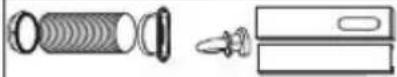 or or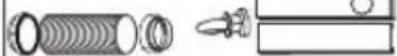 | Exhaust hose and Apaptorl and Adaptor B(flat mouth or round mouth :depending on models)Window Slider Kit and bolt | 1 set |
 | Wall Exhaust Adaptor A( × | 1 pc |
 | Adaptor B(round mouth)( × | 1 pc |
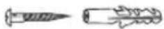 | Expansion Plug and wooden screw( ) × | 4/ pc |
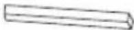 | Foam seal | 3/pc |
 | Remote Controller and Battery(For remote control models only) | 1pc |
 | Drain hose and drain hose adaptor( × | 1pc |
NOTE: Optional parts( × ), some models without.
- Check all the accessories are included in the package and please refer to the installation instructions for their usage.
NOTE: All the illustrations in this manual are for explanation purpose only. Your air conditioner may be slightly different. The actual shape shall prevail.
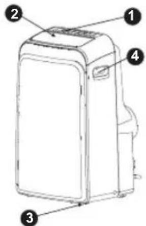
Fig.1
NAMES OF PARTS
Front
1 Operation panel
2 Horizontal louver blade (swing automatically)
3 Caster
4 Carrying handle (both sides)
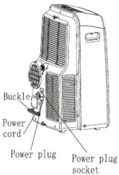
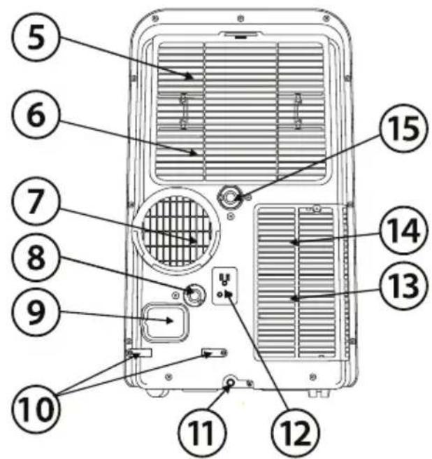
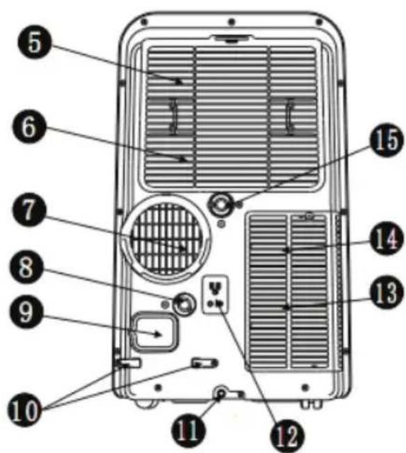
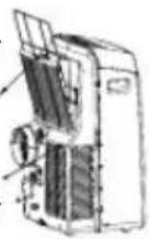
Rear
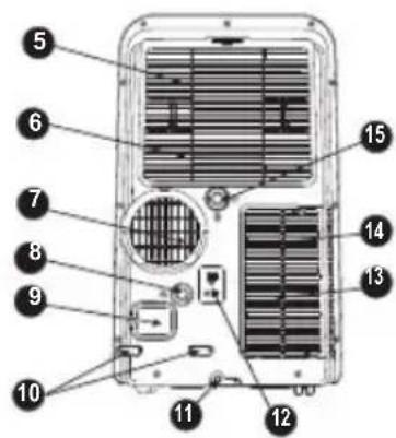
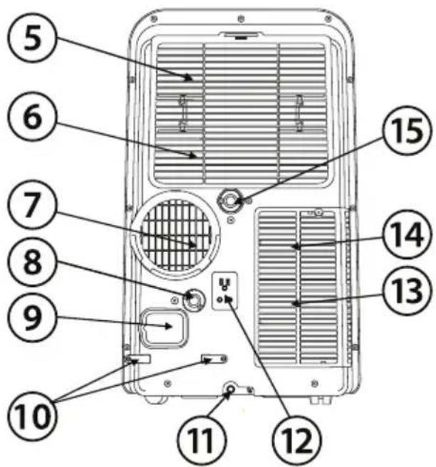
Fig.2
5 Upper air filter (Behind the grille)
6 Upper air intake
7 Air outlet
8 Drain outlet (only for Pump heating model)
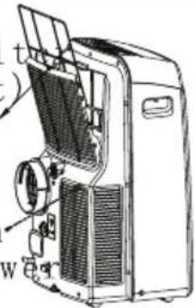
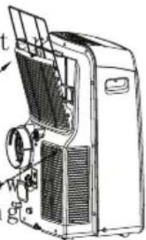
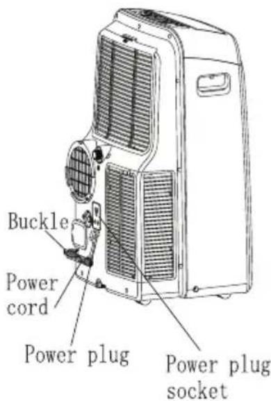
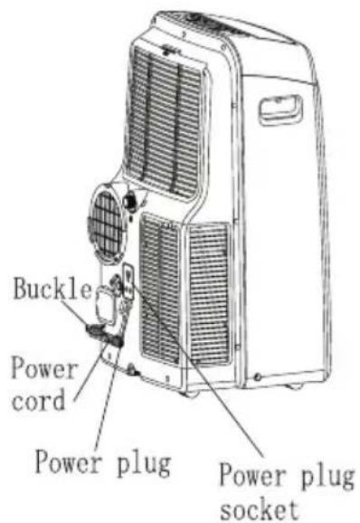
9 Power cord outlet
10 Power cord buckle (Used only when storing the unit)
11 Bottom tray drain outlet
12 Power plug socket (Use only when storing the unit)
13 Lower air filter (Behind the grille)
14 Lower air intake
15 Drain outlet
ELECTRONIC CONTROL OPERATING INSTRUCTIONS
Before you begin, thoroughly familiarize yourself with the control panel and remote controller and all its functions, then follow the symbol for the functions you desire.
The unit can be controlled by the unit control panel alone or with the remote controller.
NOTE: This manual does not include Remote Controller Operations, see the <
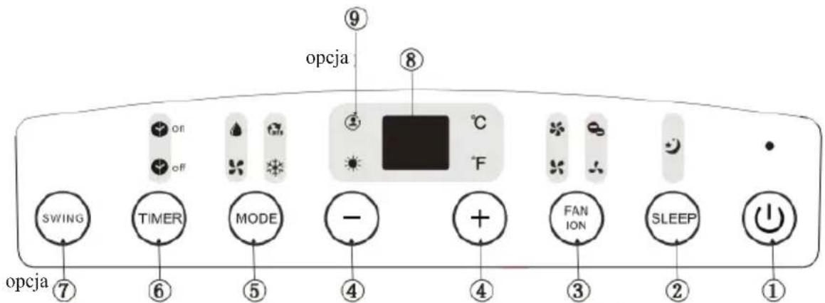
OPERATION PANEL OF THE AIR CONDITIONER
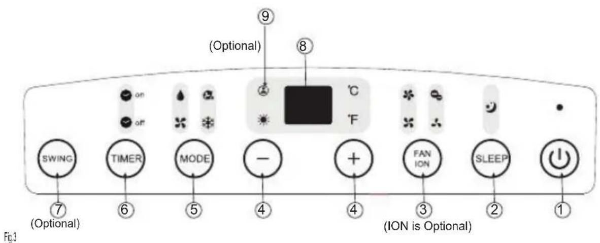
①POWER button
Power switch on/off.
2SLEEP button
Used to initiate the SLEEP operation.
③FAN/ION button (ION is optional)
Control the fan speed. Press to select the fan speed in four steps-LOW, MED, HI and AUTO. The fan speed indicator light illuminates under different fan settings except AUTO speed. When select AUTO fan speed, all the fan indicator lights turn dark.
NOTE: Press this button for 3 seconds to initiate ION feature. The ion generator is energized and will help to remove pollen and impurities from the air, and trap them in the filter. Press it for 3 seconds again to stop the ION feature.
4UP() and DOWN() button
Used to adjust (increasing/decreasing) temperature settings(1 C/2 F increments) in a range of 17 C(62 F) to 30 C(88 F) or the TIMER setting in a range of 0\~24hrs..
NOTE: The control is capable of displaying temperature in degrees Fahrenheit or degrees Celsius. To convert from one to the other, press and hold the Up and Down buttons at the same time, for 3 seconds.
⑤MODE select button
Selects the appropriate operating mode. Each time you press the button, a mode is selected in a sequence that goes from AUTO, COOL, DRY, FAN and HEAT(cooling only models without). The mode indicator light illuminates under the different mode settings.
6TIMER button
Used to initiate the AUTO ON start time and AUTO OFF stop time program, in conjunction with the + & buttons. The timer on/off indicator light illuminates under the timer on/off settings.
7 SWING button
(Applicable to the models with auto swing feature. Used to initiate the Auto swing feature. When the operation is ON, press the SWING button can stop the louver at the desired angle.
8 LED Display
Shows the set temperature in "oC" or "oF" and the Auto-timer settings. Wh ile on DRY and FAN modes, it shows the room temperature.
Error codes and protection code:
E1- Room temperature sensor error-Unplug the unit and plug it back in. If error repeats, call for service.
E2- Evaporator temperature sensor error-
Unplug the unit and plug it back in.
If error repeats, call for service.
E3- Conenser temperature sensor error-Unplug the unit and plug it back in. If error repeats, call for service.
E4- Display panel communication error-Unplug the unit and plug it back in. If error repeats, call for service.
P1- Bottom tray is full - Connect the drain hose and drain the collected water away. If protection repeats, call for service.
9 FOLLOW ME/TEMP SENSING feature(optional)
NOTE: This feature can be activated from the remote control ONLY. The remote control serves as a remote thermostat allowing for the precise temperature control at its location.
To activate the Follow Me/Temp Sensing feature, point the remote control towards the unit and press the Follow Me/Temp Sensing button. The remote display is actual temperature at its location. The remote control will send this signal to the air conditioner every 3 minutes interval until press the Follow Me/Temp Sensing button again. If the unit does not receive the Follow Me/Temp Sensing signal during any 7 minutes interval, the unit will beep to indicate the Follow Me/Temp Sensing mode has ended.
Operating Instructions
COOL operation
- Press the "MODE" button until the "COOL" indicator light comes on.
- Press the ADJUST buttons "+" or "-" to select your desired room temperature. The temperature can be set within a range of 17°C-30°C/62°F-88°F.
- Press the "FAN SPEED" button to choose the fan speed.
HEAT operation (cooling only models without)
- Press the "MODE" button until the "HEAT" indicator light comes on.
- Press the ADJUST buttons "+" or "-" to select your desired room temperature. The temperature can be set within a range of 17°C-30°C/62°F-88°F.
-
Press the "FAN SPEED" button to choose the fan speed. For some models, the fan speed can not be adjusted under HEAT mode.
-
Press the "MODE" button until the "DRY" indicator light comes on.
- Under this mode, you cannot select a fan speed or adjust the temperature. The fan motor operates at LOW speed.
- Keep windows and doors closed for the best dehumidifying effect.
- Do not put the duct to window.
AUTO operation
- When you set the air conditioner in AUTO mode, it will automatically select cooling, heating(cooling only models without), or fan only operation depending on what temperature you have selected and the room temperature.
- The air conditioner will control room temperature automatically round the temperature point set by you.
- Under AUTO mode, you can not select the fan speed.
FAN operation
- Press the "MODE" button until the "FAN" indicator light comes on.
- Press the "FAN SPEED" button to choose the fan speed. The temperature cannot be adjusted.
- Do not put the duct to window.
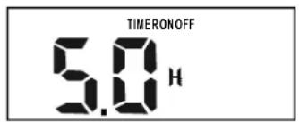
TIMER operation
- When the unit is on, press the Timer button will initiate the Auto-off stop program, the TIMER OFF indicator light illuminates. Press the UP or down button to select the desired time. Press the TIMER button again within 5 seconds, the Auto-on start program is initiated. And the TIMER ON indicator light illuminates. Press the up or down button to select the desired Auto-on start time.
- When the unit is off, press the Timer button to initiate the Auto-on start program, press it again within five seconds will initiate the Auto-off stop program.
- Press or hold the UP or DOWN button to change the Auto time by 0.5 hour increments, up to 10 hours, then at 1 hour increments up to 24 hours. The control will count down the time remaining until start.
-
The system will automatically revert back to display the previous temperature setting if there is no operation in a five seconds period.
-
Turning the unit ON or OFF at any time or adjusting the timer setting to 0.0 will cancel the Auto Start/Stop timer program.
- When the malfunction (E1,E2,E3 or E4) occurs, the Auto Start/Stop timed program will also be cancelled.
SLEEP operation
Press this button, the selected temperature will increase(cooling) or decrease(heating) by 1 °C/2°F^ 30 minutes. The temperature will then increase (cooling) or decrease (heating) by another 1 °C/2°F^ after an additional 30 minutes. This new temperature will be maintained for 7 hours before it return to the originally selected temperature. This ends the Sleep mode and the unit will continue to operate as originally programmed. NOTE: This feature is unavailable under FAN or DRY mode.
Other features
Auto-Restart(on some models)
If the unit breaks off unexpectedly due to the power cut, it will restart with the previous function setting automatically when the power resumes.
Wait 3 minutes before resuming operation
After the unit has stopped, it can not be restarted operation in the first 3 minutes. This is to protect the unit. Operation will automatically start after 3 minutes.
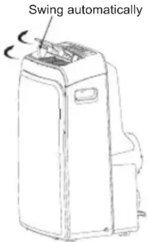
Fig.4
Air flow direction adjustment
The louver can be adjusted automatically
- Adjust the air flow direction automatically (Fig.4):
- When the Power is ON, the louver opens fully. Press the SWING button on the panel or remote controller to initiate the Auto swing feature.
- The louver will swing up and down automatically.
- Please do not adjust the louver manually.
INSTALLATION INSTRUCTIONS
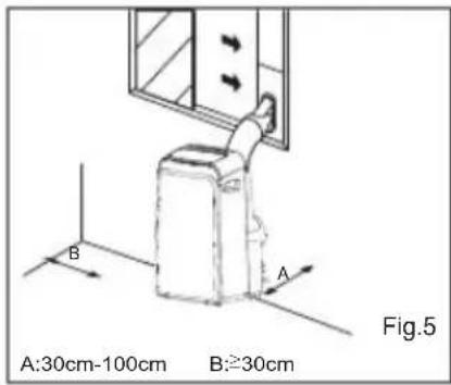
Location
- The air conditioner should be placed on a firm foundation to minimize noise and vibration. For safe and secure positioning, place the unit on a smooth, level floor strong enough to support the unit.
- The unit has casters to aid placement, but it should only be rolled on smooth, flat surfaces. Use caution when rolling on carpet surfaces. Do not attempt to roll the unit over objects.
- The unit must be placed within reach of a properly rated grounded socket.
- Never place any obstacles around the air inlet or outlet of the unit.
- Allow 30cm to 100cm of space from the wall with for efficient air-conditioning.
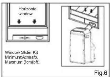
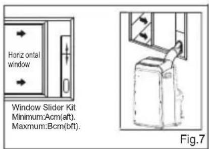
Window slider kit Installation
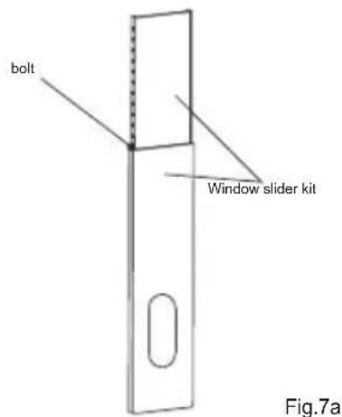
Your window slider kit has been designed to fit most standard "Vertical" and "horizontal" window applications, However, it may be necessary for you to improvise/modify some aspects of the installation procedures for certain types of window. Please refer to Fig. 6& Fig.7 for minimum and maximum window openings. Window slider kit can be fixed with a bolt (see Fig.7a).
Note: If the window opening is less than the mentioned minimum length of the window slider kit, cut that one with a hole in it short to fit for the window opening. Do never cut out the hole in window slider kit.
| A a | B b | |||
| Type I | 67.5 | 2.22 12 | 3 4.04 | |
| Type II | 56.2 | 1.84 98 | 2 3.22 |
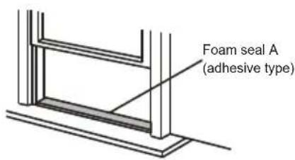
Fig.8
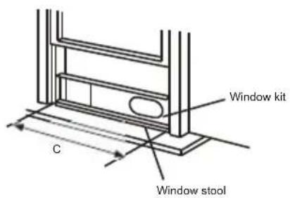
Fig.9
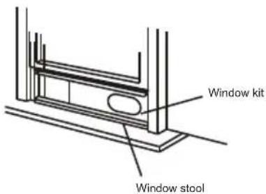
Fig.10
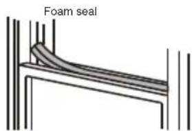
Fig.11
Installation in a double-hung sash window
-
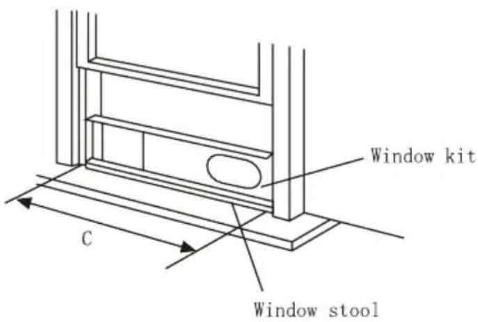
Cut the foam seal(adhesive type) to the proper length and attach it to the window stool. Fig.8
-
Attach the window slider kit to the window stool. Adjust the length of the window slider kit according to the width of window, shorten the adjustable window kit if the width of window is less than 26.5 (Type I) or 22.1 (Type II) inches Open the window sash and place the window slider kit on the window stool. Fig.9
-
Cut the foam seal(adhesive type) to the proper length and attach it on the top of the window. Shown as in Fig.10
-
Close the window sash securely against the window.
-
Cut the foam seal to an appropriate length and seal the open gap between the top window sash and outer window sash. Shown as in Fig.11.
| C | |
| Type I | 26.5 ~ 48.0 |
| Type II | 22.1 ~ 38.6 |
natural_image
Pure technical line drawing of a rectangular frame with no text, numbers, or symbolsFoam seal A (adhesive type)
Fig.12
Window panel
natural_image
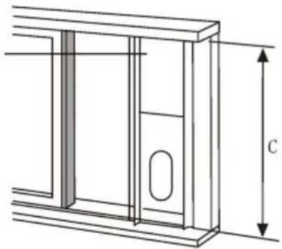
Technical line drawing of a door frame with height dimension labeled 'C' (no text or symbols beyond the label)Fig.13
natural_image
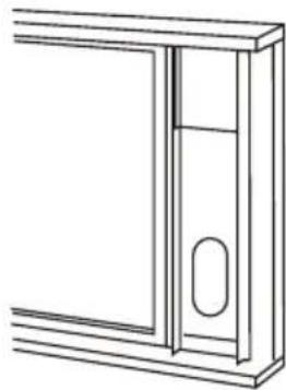
Pure technical line drawing of a door or cabinet frame without any text, numbers, or symbolsFig.14
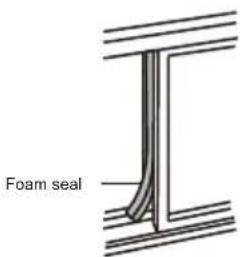
Fig.15
Installation in a sliding sash window
-
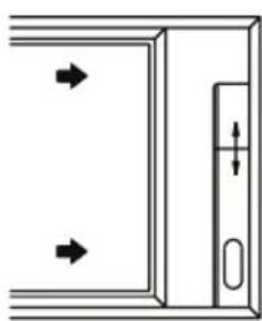
Cut the foam seal(adhesive type) to the proper length and attach it to the window frame. See Fig.12.
-
Attach the window slider kit to the window stool. Adjust the length of the window slider kit according to the width of window, shorten the adjustable window kit if the width of window is less than 26.5 (Type I) or 22.1 (Type II) inches. Open the window sash and place the window slider kit on the window stool. See Fig.13.
-
Cut the foam seal(adhesive type) to the proper length and attach it on the top of the window. Shown as in Fig.14.
-
Close the sliding sash securely against the window.
-
Cut the foam seal to an appropriate length and sea the open gap between the top window sash and outer window sash. Shown as in Fig.15.
NOTE: All the illustrations in this manual are for explanation purpose only. Your unit may be slightly different. The actual shape shall prevail.
| C | |
| Type I | 26.5 ~ 48.0 |
| Type II | 22.1 ~ 38.6 |
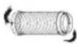
Fig.16a
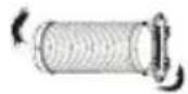
Fig.16b
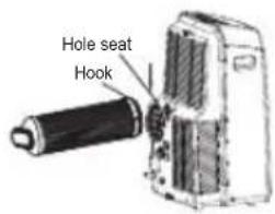
Fig.17
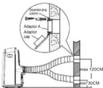
Fig.18
natural_image
Diagram showing a pipe with a diagonal line crossing through it, no text or symbols presentFig.19
Exhaust hose installation:
The exhaust hose and adaptor must be installed or removed in accordance with the usage mode.
| COOL,HEAT(heat pump type) or AUTO mode | Install |
| FAN,DEHUMIDIIFY or HEAT(electrical heat type) mode | Remove |
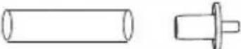
- Install the adaptor B and adaptor I onto the exhaust hose as shown in Fig.16a or Fig.16b. Refer to the previous pages for window kit installation.
- Resort the hook of the Exhaust hose into the hole seat of the air outlet and slide down the Exhaust hose along the arrow direction (See Fig.17) for installation.
The exhaust hose can be installed into the wall
(Not applicable to the units without adaptor A, expansion plugs and wooden screws of Accessories).
- Prepare a hole in the wall. Install the wall Exhaust adaptor A onto the wall(outside) by using 4 expansion plugs and wooden screws, be sure to fix thoroughly. (See Fig.18)
- Attach the Exhaust hose to wall Exhaust adaptor A.
Note:
Cover the hole using the adaptor cap when not in use.
- The exhaust hose can be compressed or extended moderately according to the installation requirement, but it is desirable to keep the hose length to a minimum.
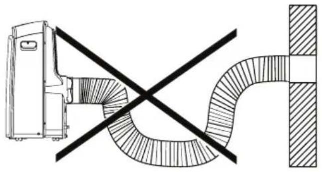
IMPORTANT:
DO NOT OVER BEND THE EXHAUST HOSE (SEE Fig.19)

CAUTION:
Make sure that there is no obstacle around the air outlet of the exhaust hose (in the range of 500mm) in order to the exhaust system works properly.
natural_image
Hand-drawn sketch of a server rack with a handle and a checkmark symbol (no text or labels)Fig.21a
natural_image
Diagram of a device with a pointer and cross mark, no readable text or symbols presentFig.21b
natural_image
Line drawing of a large industrial air conditioner unit with cooling fins and a downward arrow indicator (no text or symbols)Fig.22
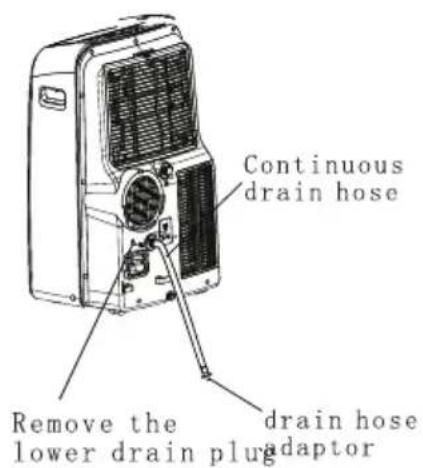
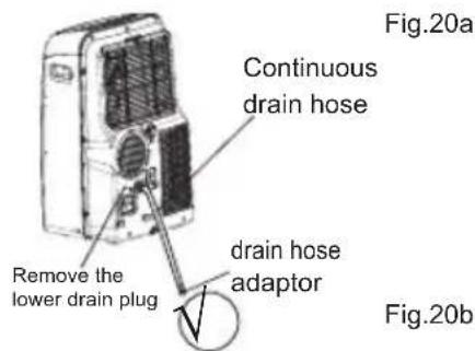
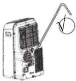
Water drainage:
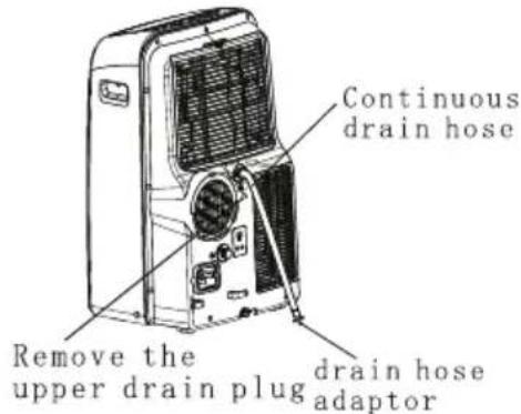
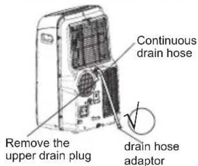
- During dehumidifying modes, remove the upper drain plug from the back of the unit, install the drain connector(5/8 universal female mender) with 3/4 hose(locally purchased). For the models without drain connector, just attach the drain hose to the hole. Place the open end of the hose adaptor directly over the drain area in your basement floor. Please refer to Fig.20a.
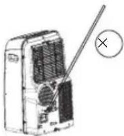
- During heating pump mode, remove the lower drain plug from the back of the unit, install the drain connector(5/8 universal female mender) with 3/4 hose(locally purchased). For the models without drain connector, just attach the drain hose to the hole. Place the open end of the hose adaptor directly over the drain area in your basement floor. Please refer to Fig.20b. NOTE: Make sure the hose is secure so there are no leaks.Direct the hose toward the drain,making sure that there are no kinks that will stop the warter flowing.Place the end of the hose into the drain and make sure the end of the hose is down to let the water flow smoothly.(See Fig.20a,20b,21a).Do never let it up.(See Fig.21b).
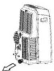
- When the water level of the bottom tray reaches a predetermined level, the unit beeps 8 times, the digital display area shows "P1". At this time the air conditioning/dehumidification process will immediately stop. However, the fan motor will continue to operate(this is normal). Carefully move the unit to a drain location, remove the bottom drain plug and let the water drain away(Fig.22). Reinstall the bottom drain plug and restart the machine until the "P1" symbol disappears. If the error repeats, call for service.
NOTE: Be sure to reinstall the bottom drain plug before using the unit.
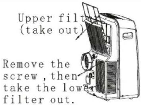
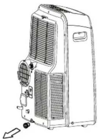
Upper filter (take out)
Remove the screw, then take the lower filter out.
Fig.23
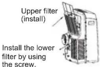
Fig.24
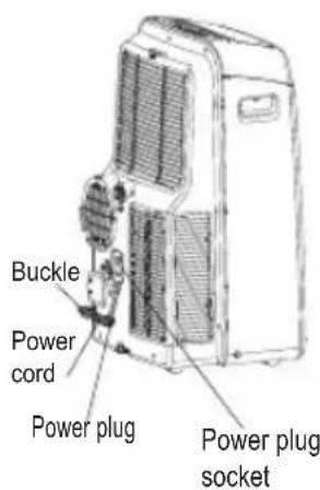
Fig.25
CARE AND MAINTENANCE
IMPORTANT:
1) Be sure to unplug the unit before cleaning or servicing.
2) Do not use gasoline, thinner or other chemicals to clean the unit.
3) Do not wash the unit directly under a tap or using a hose. It may cause electrical danger.
4) If the power cord is damaged, it should be repaired by manufacture or its agency.
1. Air filter
- Clean the air filter at least once every two weeks to prevent inferior fan operation because of dust.
- Removal This unit has two filters. Take the upper filter out along the arrow direction (Fig.23), then take the filter down. Remove the lower filter by loosening the screw, taking out the filter as shown in Fig.23.
- Cleaning Wash the air filter by immersing it gently in warm water (about 40_oC/104_oF ) with a neutral detergent. Rinse the filter and dry it in a shady place.
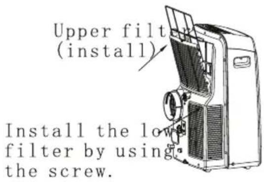
- Mounting Install the upper air filter after cleaning, and install the lower filter by using the screw (see Fig.24).
2. Unit enclosure
- Use a lint-free cloth soaked with neutral detergent to clean the unit enclosure. Finished by a dry clean cloth.
3. Unit idle for a long time
- Remove the rubber plug at the back of the unit and attach a hose to drain outlet. Place the open end of the hose directly over the drain area in your basement floor (See Fig.20 & 21).
- Remove the plug from the bottom drain outlet, all the water in the bottom tray would drain out (See Fig.22).
- Keep the appliance running on FAN mode for half a day in a warm room to dry the appliance inside and prevent mold forming.
- Stop the appliance and unplug it, wrapped the cord and bundle it with the tape(Fig.25). Remove the batteries from the remote controller.
- Clean the air filter and reinstall it.
TROUBLE SHOOTING
| TROUBLES | POSSIBLE CAUSES | SUGGEST REMEDIES |
| 1. Unit does not Start when Pressing on/off Button | - P1 appears in the display window | Drain the water in the bottom tray. |
| - Room temperature is lower than the set temperature.(Cooling mode) | Reset the temperature. | |
| 2. Not cool enough | - The windows or doors in the room are not closed. | Make sure all the windows and doors are closed. |
| - There are heat sources inside the room. | Remove the heat sources if possible. | |
| - Exhaust air duct is not connected or blocked. | Connect the duct and make sure it can function properly. | |
| - Temperature setting is too high. | Decrease the set temperature. | |
| - Air filter is blocked by dust. | Clean the air filter. | |
| 4. Noisy or vibration | - The ground is not level or not flat enough. | Place the unit on a flat, level ground if possible. |
| 5. Gurgling sound | - The sound comes from the flowing of the refrigerant inside the air-conditioner. | It is normal. |
| 6. Power shut off at Heating mode | - The automa tic over heat protection function. Wh en the temp erature at the air outlet exceed 70 °C/158 °F ,the device will stop. | Switch on again after the unit has cool down. |
AIR CONDITIONER
Thank you very much for purchasing our air conditioner. Please read this owner's manual carefully before using your air conditioner.
CONTENTS
Handling the remote controller ....2
Remote controller Specifications.... 3
Function buttons .... 4
Indicators on LCD 6
How to use the buttons ....7.
Auto operation.... 7
Cooling/Heating/Fan operation.... 7
Dehumidifying operation 8
Swing operation.... 8
Timer operation.... 9
ECONOMY operation 12
Handling the remote controller
Location of the remote controller.
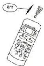
- Use the remote controller within a distance of 8 meters from the appliance, pointing it towards the receiver. Reception is confirmed by a beep.
CAUTIONS
- The air conditioner will not operate if curtains, doors or other materials block the signals from the remote controller to the indoor unit.
- Prevent any liquid from falling into the remote controller. Do not expose the remote controller to direct sunlight or heat.
If the infrared signal receiver on the indoor unit is exposed to direct sunlight, the air conditioner may not function properly. Use curtains to
• prevent the sunlight from falling on the receiver.
If other electrical appliances react to the remote controller. either move these appliances or consult your local dealer.
Replacing batteries
The remote controller is powered by two dry batteries(R03/LR03X2) housed in the rear part and protected by a cover.
(1) Remove the cover by pressing and sliding o
(2) Remove the old batteries and insert the new batteries, placing the(+) and (-) ends correctly.
(3) Reattach the cover by sliding it back into position.
NOTE: When the batteries are removed, the remote controller erases all programming. After inserting new batteries, the remote controller must be reprogrammed.
CAUTIONS
- Do not mix old and new batteries or batteries of a different type.
- Do not leave the batteries in the remote controller if it is not going to be used for 2 or 3 months.
- Dispose of the old batteries in the special containers to be found in the sales outlets.
Remote Controller Specifications
| Model | ACP-09PT25AEH, ACP-12PT35AEH |
| Rated Voltage | 3.0V(Dry batteries R03/LR03 × 2) |
| Lowest Voltage of CPU Emitting Signal | 2.0V |
| Signal Receiving Range | 8m (when using 3.0 voltage, it Gets 11m) |
| Environment | -5°C~60°C(-41°F~140°F) |
Performance Feature
- Operating Mode: AUTO, COOL, DRY, HEAT(Cooling only model without), and FAN.
- Timer Setting Function in 24 hours.
- Indoor Setting Temperature Range: 17°C\~30°C(62°F\~88°F).
- Full function of LCD (Liquid Crystal Display)
- Back light emitting.
NOTE: All the illustrations in this manual are for explanation purpose only. Your air conditioner may be slightly different. The actual shape shall prevail.
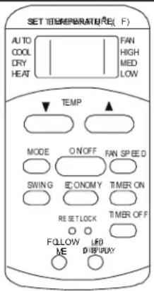
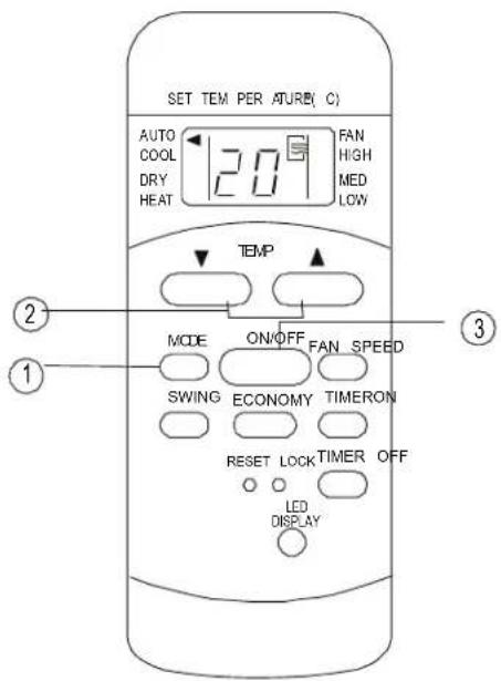
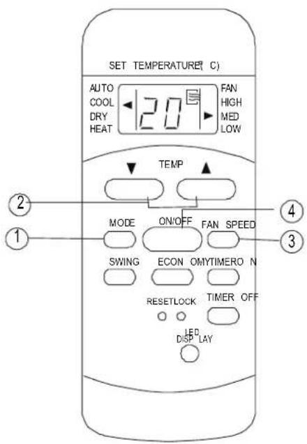
Function buttons
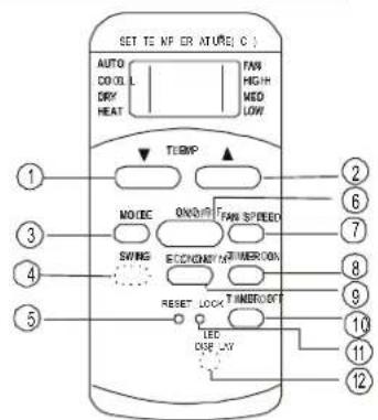
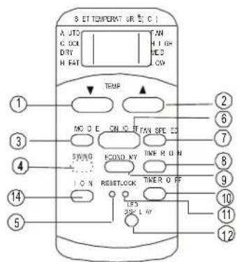
① TEMP DOWN Button
Push this button to decrease the indoor temperature setting in 1°C(2 F) increments to 30 C(88
② TEMP UP Button
Push this button to increase the indoor temperature setting in 1^ C( 2^ F) increments to 17^ C( 62^ F).
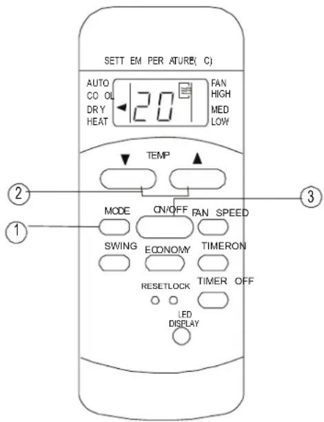
③ MODE Button
Each time the button is pressed, the operation mode is selected in the sequence of the following:

NOTE: Heat mode is for Cooling & Heating models only.
4 SWING Button(on some models)
Used to stop or start louver movement and set the desired up/down airflow direction.
⑤ RESET Button
Once the recessed RESET button is pressed, all of the current settings will be cancelled and the controller will return to the initial sett
6 ON/OFF Button
Operation starts when this button is pressed and stops when the button is pressed again.
⑦ FAN SPEED Button
Used to select the fan speed in four steps: → Auto→ Low→ Med→ High
- Some models have no MED FAN feature.
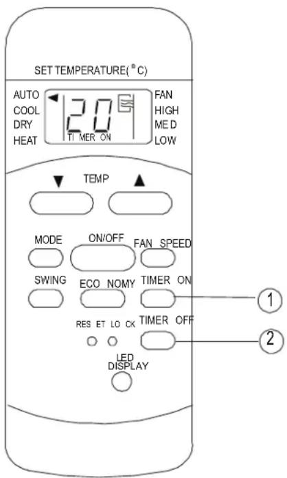
8 TIMER ON Button
Press this button to activate the Auto-on time setting. Each press will increase the time sett in 30 minutes increments, up to 10 hours, the 1 hour increments up to 24 hours. To cancel Auto-on time setting, just press the button until the time setting is 0.0.
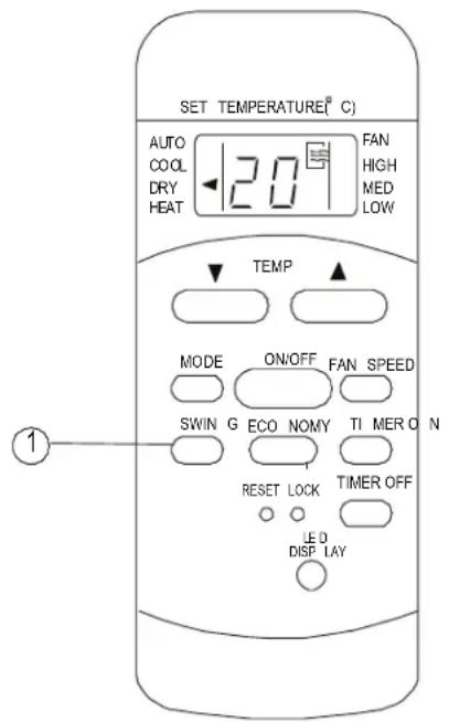
⑨ ECONOMY(SLEEP) Button
Select this function during the sleeping time. I can maintain the most comfortable temperature and save energy. This function is available on COOL, HEAT or AUTO mode only.
Function buttons(continued)
NOTE: While the unit is trisining unidgr SLEEP is SLEEP mode, it would be cancelled if ON/OFF, FAN SPEED, SLE or MODE button is pressed.
⑩ TIMRT OFF Button
Press this button to activate the Auto-off time setting. Each press will increase the time settir in 30 minutes increments, up to 10 hours, the 1 hour increments up to 24 hours. To cancel Auto-off time setting, just press the button until the time setting is 0.0.
① LOCK Button
Press this recessed button to lock all current settings, and the remote controller will not accept any operation except that of the LOCK. Use the LOCK mode when you want to prevent setting from being changed accidentally. Press the LOCK button again to cancel the LOCK function. A I symbol will appear on the remote controller diswhen the lock function is activated.
② LED Display Button
Press this button to clear the display on the indoor unit, press it again to light the display
13 FOLLOW ME Button
- Press this button to initiate FOLLOW ME funct - When the Follow Me function is activated, the remote display is actual temperature at its loca. The remote control will send this signal to the conditioner every 3 minutes interval until press the Follow Me button again.
- The Follow Me function is not available under DRY and FAN mode.
- Switch the operation mode or turn off the unit cancel the follow me function automatically.
14 ION Button
When push this button, the ion generator is energized and will help to remove pollen and impurities from the air.
Indicators on LCD
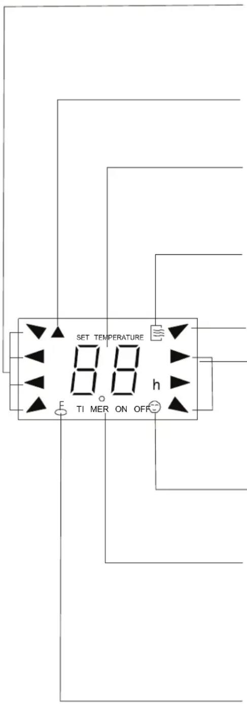
MODE display
Displays the current selected mode. Including AUTO, COOL, DRY, HEAT (cooling & heating models only) and FAN.
Transmission Indicator
This transmission indicator will light when remote con trolle r tran smits signa ls to the indoor unit.
Temp./Timer display
The tem perature se tting (from ^ 17 ℃ (62 F) to 30°C(88°F)) or timer setting (0\~24h) will be displayed. If FAN mode is selected, there will be no display.
ON/OFF display
This indicator will be disp layed when the unit is operating.
MODE display(FAN mode)
FAN SPEED display
Displays the selected fan speed: AUTO, HIGMED and LOW. Nothing displays when the fan speed is selected in AUTO speed. When AUTO or DRY Mode is selected, there will be no signals displayed.
FOLLOW ME display
When pressin g FOLLOW ME butto n in C OOL or HE AT mode, the remote sensing function is activated and this indicator displays.
TIMER display
This display area shows the setting s of the TIMER. That is, if only the Auto-on time function is set, it will display TIMER ON. If only the Auto-off time function is set, it will display TIMER OF F. If both functions are set, it will display TIMER ON OFF which indicates you have chosen both the Auto-on time and Auto-o ff tim e.
LOCK Indicator
LOCK display is displayed w hen pushing the L OC K button. Push the LOCK b utton to clear display.
How to use the buttons
Auto operation
Ensure the unit is plugged in and power is available. The OPERATION indicator on the display panel of the indoor unit illuminates.
- Press thMODE button to select Auto.
-
Press theTEMP button to set the desired temperature. The temperature can be set within a range of 17^ C(62 F)\~ 30 C in 1 C(2 increments.
-
Press the ON/OFF button to start the air conditioner.
NOTE
-
In the Auto mode, the air conditioner can logically choose the mode of Cooling, Fan, Heating and Dehumidifying by sensing the difference between the actual ambient room temperature and the set temperature on the remote controller.
-
In the Auto mode, you can not switch the fan speed. It has already been automatically controlled.
-
If the Auto mode is not comfortable for you, the desired mode can be selected manually.
Cooling /Heating/Fan operation
Ensure the unit is plugged in and power is available.
- Press the MODEton to select COOL, HEAT, (cooling & heating models only) or FAN mode.
-
Press the TEMRON to set the desired temperature. The temperature can be set within a range of 10^ C(62 F)\~30 C° in ^1 C(2 F) increments.
-
Press theAN SPEED button to s elect the fan speed in four steps- Auto, Low, Med, or High
- Press theON/OFF button to start the air conditioner.
NOTE
In the FAN mode, the setting temperature is not displayed in the remote controller and you are not able to control the room temperature either. In this case, only step 1, 3 and 4 may be performed.
Dehumidifying operation
Ensure the unit is plugged in and power is available. The OPERATION indicator on the display panel of the indoor unit illuminates.
- Press the MODEton to select DRY mode.
-
Press the TEMPTON to set the desired temperature. The temperature can be set within a range of ^ C(62 F)\~°30 C in°1 C(2 F increments.
-
Press the ON/OFFn to start the air conditioner.
NOTE
In the Dehumidifying mode, you can not switch the fan speed. It has already been automatically controlled.
Swing operation(on some models)
Use the SWING button to adjust the Up/Down airflow direction.
- When press the button once and quickly, the air flow direction setting feature of the louver activated. The moving angle of the louver is 6^ for each press. Keep pressing the button to move the louver to the desired position.
NOTE: On some models press it to initiate the A swing feature only.
- If keep pressing the SWING button without releasing for 2 more seconds, the auto swing feature of the louver is activated. The horizon louver would swing up/down automatically. Press it again to stop.
NOTE: When the louver swing or move to a position which would affect the cooling and heating effect of the air conditioner, it would automatically change the swing/moving direction.
Timer operation
press the TIMER ON button can set the auto-on time of the unit. And press the TIMER OFF button can set the auto-off time of the unit.
To set the Auto-on time.
- Press the TIMER ON button. The remote controller shows TIMER ON, the last Auto-on setting time and the signal "h" will be shown on the LCD display area. Now it is ready to reset Auto-on time to START the operation.
- Push the TIMER ON button again to set desire Auto-on time. Each time you press the button, the time increases in 30 minutes increments, up to 10 hours, then at 1 hour increments up to 2 hours.
- After setting the TIMER ON, there will be a half second delay before the remote controller transmits the signal to the air conditioner. Then, after approximately another 2 seconds, the signal "h" will disappear and the set temperature will re-appear on the LCD display window.
To set the Auto-off time.
- Press the TIMER OFF button. The remote controller shows TIMER OFF, the last Auto-off setting time and the signal "h" will be shown or the LCD display area. Now it is ready to reset the Auto-off time to START the operation.
- Push the TIMER OFF button again to set desir Auto-off time. Each time you press the button, the time increases in 30 minutes increments, up to 10 hours, then at 1 hour increments up to 2 hours.
- After setting the TIMER OFF, there will be a half second delay before the remote controller transmits the signal to the air conditioner. Then, after approximately another 2 seconds, the signal "h" will disappear and the set temperature will re-appear on the LCD display window.
IMPORTANT
- The effective operation time set by the remote controller for the timer function is limited to the following settings: 0.5, 1.0, 1.5, 2.0, 2.5, 3.0, 3.5, 4.0, 4.5, 5.0, 5.5, 6.0, 6.5, 7.0, 7.5, 8.0, 8.5, 9.0, 9.5, 10, 11, 12, 14, 15,16,17, 18, 19, 20, 21, 22, 23 and 24.
Example of Timer setting
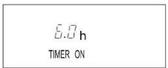
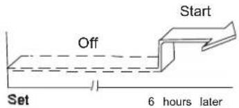
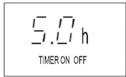
TIMER ON (Auto-on Operation)
The TIMER ON feature is useful when you want the unit to turn on automatically before say when you return home. The air conditioner will automatically start operating at the set time.
Example:
To start the air conditioner in 6 hours.
- Press the TIMER ON button, the last setting starting operation time and the "sign" show on the display area.
- Press the TIMER ON button to display "6:0h" the TIMER ON display of the remote controller
- Wait for about 3 seconds and the digital display area will show the temperature again. Now this function is activated.
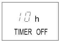
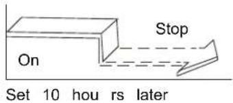
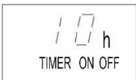
TIMER OFF
(Auto-off Operation)
The TIMER OFF feature is useful when you want the unit to turn off automatically after you go to The air conditioner will stop automatically at the s time.
Example:
To stop the air conditioner in 10 hours.
- Press the TIMER OFF button, the last setting (stopping operation time and the signal "h" will show on the display area.
- Press the TIMER OFF button to display "10h" the TIMER OFF display of the remote controller.
- Wait for about 3 seconds and the digital displa area will show the temperature again. Now this function is activated.
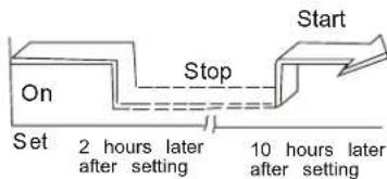
COMBINED TIMER
(Setting both ON and OFF timers simultaneously)
TIMER OFF→ TIMER ON
(On → Stop → Start operation)
This feature is useful when you want to stop the conditioner after you go to bed, and start it again the morning when you wake up or when you return home.
Example:
To stop the air conditioner 2 hours after setting and start it again 10 hours after setting.
- Press the TIMER OFF button.
- Press the TIMER OFF button again to display 2.0h on the TIMER OFF display.
- Press the TIMER ON button.
- Press the TIMER ON button again to display 10h on the TIMER ON display.
- Wait for the remote control to display the setting temperature.
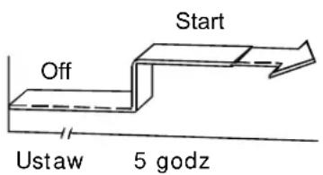
flowchart
graph TD
    A["Start"] --> B["Off"]
    B --> C["Set"]
    C --> D["2 hours later after setting"]
    D --> E["5 hours later after setting"]
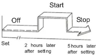
TIMER ON→ TIMER OFF
(Off→Start Stop operation)
This feature is useful when you want to start the air conditioner before you wake up and stop it after you leave the house.
Example:
To start the air conditioner 2 hours after setting, and stop it 5 hours after setting.
- Press the TIMER ON button.
- Press the TIMER ON button again to display 2.0h on the TIMER ON display.
- Press the TIMER OFF button.
- Press the TIMER OFF button again to display 5.0h on the TIMER OFF display .
- Wait for the remote control to display the setting temperature.
CAUTION
- The timer setting(TIMER ON or TIMER OFF) that in sequence occurs directly after the set time will be activated first.
ECONOMY(SLEEP) operation
When you press the ECONOMY button, the economic running function will be activated, the set temperature will increase(cooling) or decrease(heating) by 1°C(2 F) over the next 30 minutes and by another 1 C(2 F) after an additional 30 minutes. This new temperature will be maintained for 6 (on some models 7 ) hours before it returns to the originally selected temperature.(NOTE:On some models, the set temperature will increase (cooling) or decrease (heating) by 1°C(2 F) per hour for 2 hours. The new temperature will be maintained for 5 hours then the unit is off.)
NOTE: The ECONOMY/SLEEP function is only available under Cooling, Heating and AUTO operation.
JAMSTVENI LIST
VIVAX
HR
za klima uređaj
JAMSTVO
Broj jamstva
Tip uređaja
Vanjska Jedinica
Unutarnja J.1
Unutarnja J.2
Unutarnja J.3
Unutarnja J.4
Datum prodaje
Broj računa

M.P.
OPĆI PODACI
Kupac
Adresa
Poštanski broj
Grad
Telefon
MONTAŽA KLIMA UREĐAJA
Servis / Montazer
Datum montaže

M.P.