
AVIC-9DVD-2 - Car stereo PIONEER - Free user manual and instructions
Find the device manual for free AVIC-9DVD-2 PIONEER in PDF.
| Product Type | Car stereo with GPS navigation and DVD player |
| Brand | PIONEER |
| Model | AVIC-9DVD-2 |
| Power supply voltage | 12 V DC (negative ground) |
| Fuse | 7.5 A |
| Dimensions (W x H x D) | 178 x 50 x 160 mm (estimated) |
| Weight | Approximately 1.5 kg (estimated) |
| Main functions | GPS navigation, DVD player, FM/AM radio reception, voice control, rearview camera input, compatibility with Pioneer car stereos |
| Included accessories | GPS antenna with magnet, remote control (batteries included), microphone, power and connection cables, mounting brackets, trim ring, extraction keys |
| Mounting type | DIN front/rear |
| GPS antenna | Indoor (on metal plate) or outdoor (on body), magnetic attachment |
| Microphone | External, installation on sun visor or steering column |
| Safety precautions | Do not use while driving, professional installation recommended, avoid short circuits |
| Maintenance and cleaning | Clean with a soft dry cloth, do not use liquids or abrasive products |
| Spare parts and repairability | Contact an authorized Pioneer service center for repairs |
| General information | User and installation manual included, compatible with Pioneer audio systems |
Frequently Asked Questions - AVIC-9DVD-2 PIONEER
User questions about AVIC-9DVD-2 PIONEER
0 question about this device. Answer the ones you know or ask your own.
Ask a new question about this device
Download the instructions for your Car stereo in PDF format for free! Find your manual AVIC-9DVD-2 - PIONEER and take your electronic device back in hand. On this page are published all the documents necessary for the use of your device. AVIC-9DVD-2 by PIONEER.
USER MANUAL AVIC-9DVD-2 PIONEER
This product conforms to new cord colours.
ABOUT YOUR NEW DVD NAVIGATION UNIT AND THIS MANUAL
- The Pioneer DVD Navigation Unit is intended solely as an aid to you in the operation of your vehicle. It is not a substitute for your attentiveness, judgement and care while driving.
- Do not use your navigation system to route you to emergency services such as hospitals or police stations. Not all emergency service facilities are contained in the map data.
- Do not operate the DVD Navigation Unit if doing so will divert your attention from the safe operation of your vehicle. Always observe safe driving rules and follow all existing traffic regulations.
- This manual explains how to install this DVD Navigation Unit in your vehicle. Operation of this DVD Navigation Unit is explained in the separate "Operation Manual" that also came with this unit.
IMPORTANT SAFEGUARDS 3
PLEASE READ ALL OF THESE
INSTRUCTIONS REGARDING
YOUR DVD NAVIGATION
UNIT AND RETAIN THEM
FOR FUTURE REFERENCE 3
Connecting the System 4
CAUTION 4
- Before installing the unit
- To prevent damage
- Parts supplied
Connecting the system 6
- Connecting to the display with 20-pin RGB input (AVIC-8DVD II)
- Connecting to the display with 26-pin RGB input (AVH-P6400CD, AVH-P6400R, etc.)
- Connecting to the display with 20-pin RGB input (AVIC-9DVD II)
Connecting the power cord (1) 9
Connecting the power cord (2) 11
Installation 12
CAUTION 12
To guard against electromagnetic interference 13
Before installing and fixing 13
Before using the adhesive tape 13
Installing the main unit 14
- Installation notes
- Parts supplied
CAUTION - If you install with the left and right sides of the DVD Navigation Unit parallel to your vehicle's forward / backward direction
DIN Front/Rear-mount 17
DIN Front-mount 17
- Installation with the rubber bush
- Removing the Unit
DIN Rear-mount 18
- Installation using the screw holes on the side of the unit
Installing the GPS aerial 19
CAUTION
- Installation notes
Parts supplied
- When installing the aerial inside the vehicle (on the dashboard or rear shelf)
- When installing the aerial outside the vehicle (on the body)
Installing the Remote control 22
Parts supplied
- Loading the batteries
CAUTION
Remote control handling notes
- When Installing with double-sided tape
Installing the microphone 24
- Installation notes
- Parts supplied
- When installing the microphone on the sun visor
- When installing the microphone on the steering column
CAUTION
After installing the unit 27
PLEASE READ ALL OF THESE INSTRUCTIONS REGARDING YOUR DVD NAVIGATION UNIT AND RETAIN THEM FOR FUTURE REFERENCE
- Read this manual fully and carefully before installing your DVD Navigation Unit.
- Keep this manual handy for future reference.
- Pay close attention to all warnings in this manual and follow the instructions carefully.
- This unit is intended solely as an aid to you in the operation of your vehicle. It is not a substitute for your attentiveness, judgement and care while driving. Do not operate your DVD Navigation Unit if doing so will divert your attention from the safe operation of your vehicle. Always observe safe driving rules and follow all existing traffic regulations.
- This DVD Navigation Unit may in certain circumstances display erroneous information regarding the position of your vehicle, the distance of objects shown on the screen, and compass directions. In addition, the system has certain limitations, including the inability to identify one-way streets, temporary traffic restrictions and potentially unsafe driving areas. Please exercise your own judgement in light of actual driving conditions.
- As with any accessory in your vehicle's interior, the DVD Navigation Unit should not divert your attention from the safe operation of your vehicle. If you experience difficulty in operating the system or reading the display, please make adjustments while safely parked.
- Do not attempt to install or service your DVD Navigation Unit by yourself. Installation or servicing of the DVD Navigation Unit by persons without training and experience in electronic equipment and automotive accessories may be dangerous and could expose you to the risk of electric shock or other hazards.
- Please remember to wear your seat belt at all times while operating your vehicle. If you are ever in an accident, your injuries can be considerably more severe if your seat belt is not properly fastened.

CAUTION
- Pioneer does not recommend that you install or service your DVD navigation unit yourself. Installing or servicing of the product may expose you to risk of electric shock or other hazards. Refer all installation and servicing of your navigation unit to authorised Pioneer service personnel.
- Secure all wiring with cable clamps or electrical tape. Do not allow any bare wiring to remain exposed.
- Do not drill a hole into the engine compartment to connect the yellow lead of the unit to the vehicle battery. Engine vibration may eventually cause the insulation to fail at the point where the wire passes from the passenger compartment into the engine compartment. Take extra care in securing the wire at this point.
- It is extremely dangerous to allow the GPS aerial cable or microphone cable to become wound around the steering column or gearstick. Be sure to install the unit in such a way that it will not obstruct driving.
- Make sure that wires will not interfere with moving parts of the vehicle, such as the gearstick, handbrake or seat sliding mechanism.
- Do not route wires where they will be exposed to high temperatures. If the insulation heats up, wires may become damaged, resulting in a short circuit or malfunction.
- Do not cut the GPS aerial cable to shorten it or use an extension to make it longer. Altering the aerial cable could result in a short circuit or malfunction.
- Do not shorten any leads. If you do, the protection circuit may fail to work properly.
- Never feed power to other electronic products by cutting the insulation of the power supply lead of the DVD navigation unit and tapping into the lead. The current capacity of the lead will be exceeded, causing overheating.
Before installing the unit
- This unit is for vehicles with a 12-volt battery and negative grounding. Before installing it in a recreational vehicle, lorry, or bus, check the battery voltage.
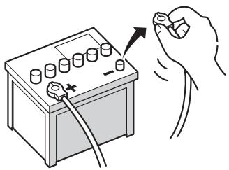
- To avoid shorts in the electrical system, be sure to disconnect the (-) battery cable before beginning installation.
To prevent damage
- When disconnecting a connector, pull the connector itself. Do not pull the lead, as you may pull it out of the connector.
- If this unit is installed in a vehicle that does not have an ACC (accessory) position on the ignition switch, the red lead of the unit should be connected to a terminal coupled with ignition switch ON/OFF operations. If this is not done, the vehicle battery may be drained when you are away from the vehicle for several hours.
- To avoid short-circuiting, cover the disconnected lead with insulating tape.
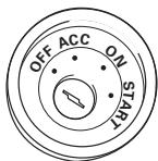
ACC position
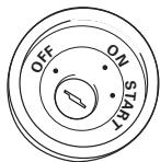
No ACC position
Parts supplied
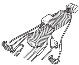
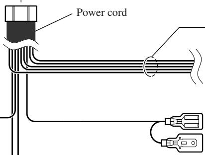
Power cord
Connector
Inter connector (AVIC-8DVD II only)
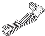
26-pin RGB cable (AVIC-9DVD II only)
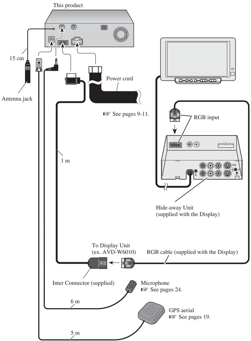
Connecting to the display with 20-pin RGB input (AVIC-8DVD II)
Connecting to the display with 26-pin RGB input (AVH-P6400CD, AVH-P6400R, etc.)
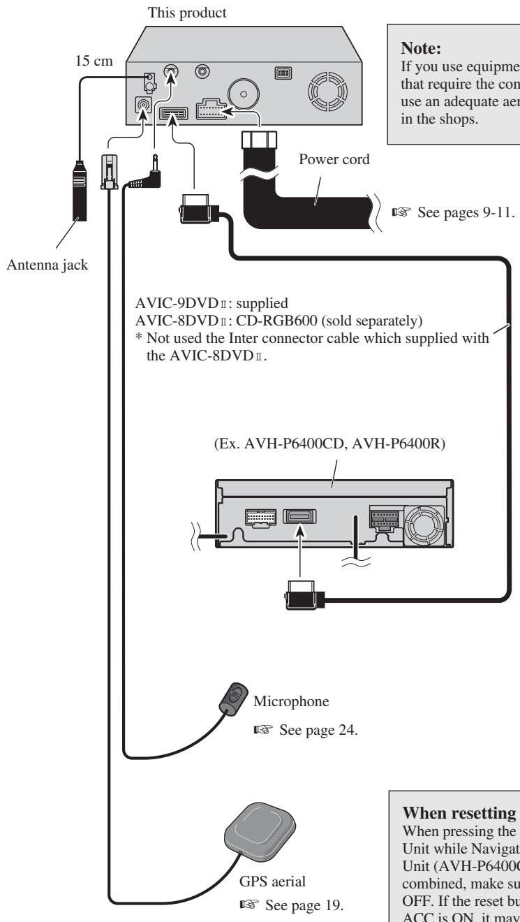
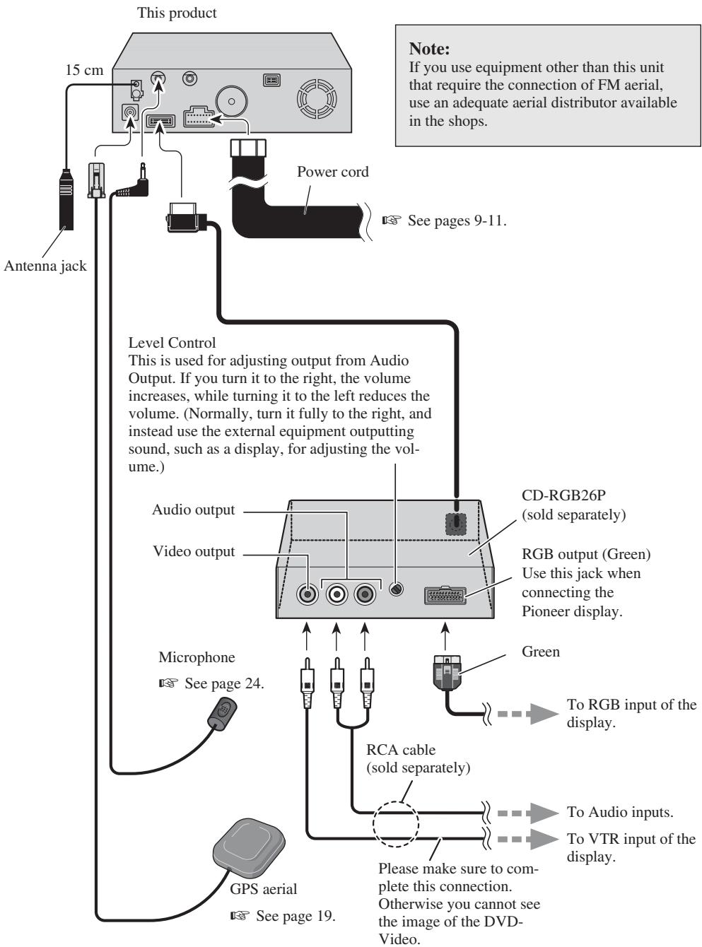
Note:
If you use equipment other than this unit that require the connection of FM aerial, use an adequate aerial distributor available in the shops.
See pages 9-11.
When resetting AV Head Unit
When pressing the reset button of AV Head Unit while Navigation System and AV Head Unit (AVH-P6400CD, AVH-P6400R) are combined, make sure that ACC is tuned OFF. If the reset button is pressed while ACC is ON, it may not work properly.
Connecting to display with 20-pin RGB input (AVIC-9DVD II)
Connecting the power cord (1)
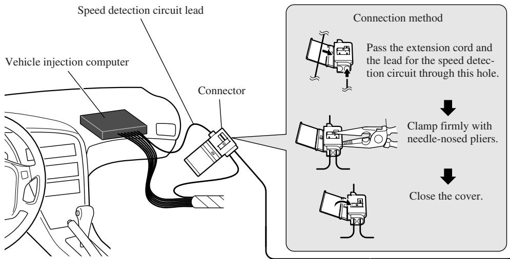
Note: The position of the speed detection circuit depends on the vehicle model. For details, consult the relevant documents from Pioneer. When making connections for a model not listed in those documents or for which connection to the speed detection circuit is too difficult, connect the separately sold ND-PG1 speed pulse generator to the pink lead.
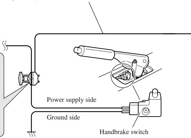
Note: The position of the handbrake switch depends on the vehicle model. For details, consult the vehicle owner's manual or dealer.
Pink (CAR SPEED SIGNAL INPUT)
The mobile navigation system is connected here to detect the distance the vehicle travels. Always connect the vehicle's speed detection circuit or the ND-PG1 speed pulse generator, sold separately. Failure to make this connection will increase errors in the location display.
WARNING: IMPROPER CONNECTION MAY RESULT IN SERIOUS DAMAGE OR INJURY INCLUDING ELECTRICAL SHOCK, AND INTERFERENCE WITH THE OPERATION OF THE VEHICLE'S ANTILOCK BRAKING SYSTEM, AUTOMATIC TRANSMISSION AND SPEEDMETER INDICATION.
Lightgreen
Used to detect the ON/OFF status of the handbrake. This lead must be connected to the power supply side of the handbrake switch. If this connection is made incorrectly or omitted, certain functions of your navigation system will be unusable.
This product
Note:
Cords for this product and those for other products may be different colours even if they have the same function. When connecting this product to another product, refer to the supplied Installation manuals of both products and connect cords that have the same function.
Black, Orange/white, Red, Yellow
See Page 11.
Yellow/black
When combining this navigation unit with a Pioneer car stereo, if the car stereo has yellow/black leads, connect them to those leads. In this way, when the guidance audio is output and when you operate the system by voice, the vehicle stereo is automatically muted to reduce the vehicle stereo volume.
Purple/white (REVERSEGEAR SIGNAL INPUT)
This is connected so that the navigation system can detect whether the vehicle is moving forwards or backwards. Connect the purple/white lead to the lead whose voltage changes when the reverse gear is engaged. Unless connected, the sensor may not detect your vehicle travelling forward/backward properly, and thus the position of your vehicle detected by the sensor may be misaligned from the actual position.
Note: When you use the ND-PG1 speed pulse generator (sold separately), please make sure to connect it.
Connection method
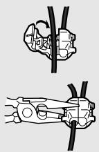
Clamp the reversing lamp lead.

Clamp firmly with needle-nosed pliers.
Fuse resistor
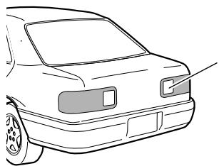
Check the position of your vehicle's reversing lamp (the one that lights up when the gearstick is in reverse [R]) and find the reversing lamp lead in the boot.
Reversing lamp lead.
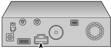
Connecting the power cord (2)
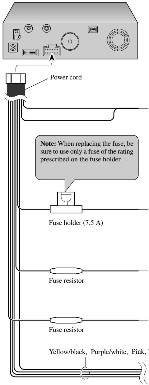
This product
Note:
Cords for this product and those for other products may be different colours even if they have the same function. When connecting this product to another product, refer to the supplied Installation manuals of both products and connect cords that have the same function.
Black
To vehicle (metal) body. To keep electromagnetic noise from the vehicle body out of the mobile navigation system, attach this lead near the main unit.
Note: The yellow, red, and orange/white leads should be connected to the opposite side of the fusebox terminals from the battery.
Yellow
To the terminal always supplied with power regardless of ignition switch position.
Red
To the electric terminal controlled by the ignition switch (12 V DC) ON/OFF.
Do not connect this lead to power source terminals to which power is continuously supplied. If the lead is connected to such terminals, the battery may be drained.
Orange/white
To lighting switch terminal.
See pages 9-11.

CAUTION
-
Pioneer does not recommend that you install or service your DVD navigation unit yourself. Installing or servicing the product may expose you to risk of electric shock or other hazards. Refer all installation and servicing of your navigation unit to authorised Pioneer service personnel.
-
Never install the unit in places where:
-
It could injure the driver or passengers if the vehicle stops suddenly.
-
It may interfere with the driver's operation of the vehicle, such as on the floor in front of the driver's seat.
-
Make sure there is nothing behind the dashboard or panelling when drilling holes in them. Be careful not to damage fuel lines, brake lines or power cables.
- When using screws, do not allow them to come into contact with any electrical lead. Vibration may damage wires, leading to a short circuit or other damage to the vehicle.
- To ensure proper installation, use the supplied parts in the manner specified. If any parts other than the supplied ones are used, they may damage internal parts of the unit or they may work loose and the unit may become detached.
- It is extremely dangerous to allow the GPS aerial lead or microphone lead to become wound around the steering column or gearstick. Be sure to install the unit in such a way that it will not obstruct driving.
- Make sure that leads cannot get caught in a door or the sliding mechanism of a seat, resulting in a short circuit.
- Please confirm the proper function of your vehicle's other equipment following installation of the DVD navigation unit.
To guard against electromagnetic interference
-
In order to prevent interference, set the following items as far as possible from the main unit of this Navigation System, other cables or leads:
-
TV aerial and aerial lead
- FM, MW/LW aerial and its lead
- GPS aerial and its lead
In addition you should lay each aerial lead as far as possible from other aerial leads.
Do not bind them together, lay them together, or cross them.
Such electromagnetic noise would increase the error for the location display.
Before installing and fixing
- Consult with your nearest dealer if installation requires the drilling of holes or other modifications of the vehicle.
- Before finally installing the unit, connect the wiring temporarily, making sure it is all connected up properly, and the unit and the system work properly.
Before using the adhesive tape
- Make sure the surface is free of moisture, dust, grime, oil, etc. before affixing the tape.
Installation notes
-
Do not install the main unit in places where it may become subject to high temperatures or humidity, such as:
-
Places close to a heater outlet.
- Places exposed to direct sunlight, such as on top of the dashboard or the rear shelf.
-
Places that may be splashed by rain, for example close to the door.
-
The installation strength will depend on the vehicle model and the installation position. Choose a position where the main unit can be firmly installed, and install it securely. If the main unit is not securely fastened, the errors in location display will be greater.
- Do not install the main unit on the board covering the spare tyre or other places which are subject to vibration.
- When the main unit is installed under a front seat, ensure that it does not obstruct the sliding action of the seat.
- Do not install the main unit where it will be under luggage. Strong mechanical shock to the main unit would increase the errors in location display.
- Avoid installing the main unit in places where it will interfere with loading and unloading of the spare tyre, jack, tools, etc.
- Check that a disc or a PC card can be ejected with the main unit installed.
- Install the main unit on a surface within +30 degrees to -15 degrees tolerance (within five degrees to the left or right of your vehicle's direction of travel). A surface tilted more than this would increase the errors in location display.
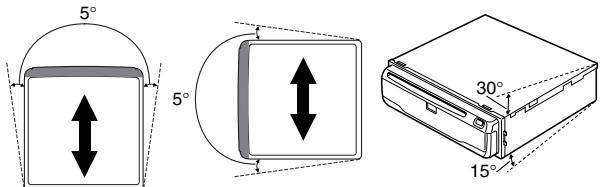
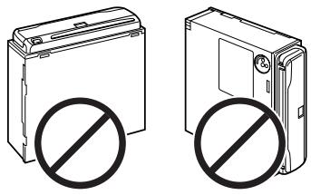
- Do not install the main unit vertically. Installing it this way can cause it to function improperly.
Parts supplied
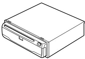
Main unit
Screw
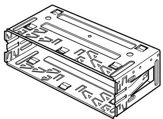
Holder
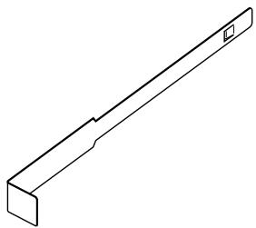
Extraction Key (2 pcs.)

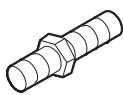
Rubber bush

Binding screw (5× 6mm) (4 pcs.)

Flush surface screw (5× 6mm) (4 pcs.)
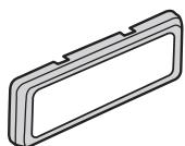
Frame

CAUTION
- Install with the left and right sides of the DVD Navigation Unit perpendicular or parallel to your vehicle's direction of travel. Do not install diagonally to your vehicle's direction of travel or the current location will be displayed incorrectly.
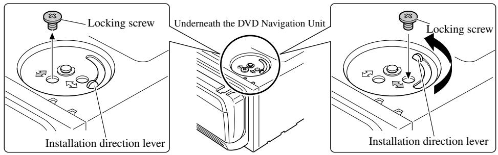
- If you install the left and right sides of the DVD Navigation Unit parallel to your vehicle's direction of travel, switch the installation direction lever, and attach the locking screw to the “ ” side, or else the G sensor mounted in the DVD Navigation Unit will not operate correctly.
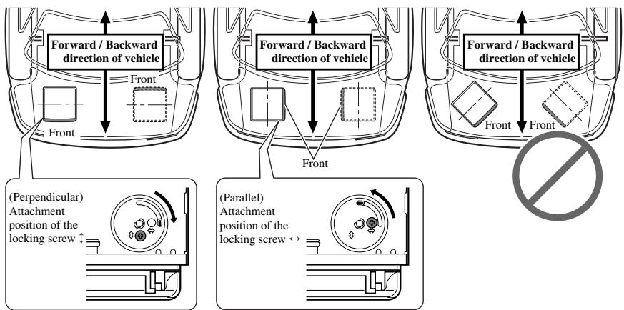
If you install with the left and right sides of the DVD Navigation Unit parallel to your vehicle's forward / backward direction
If you install with the left and right sides of the DVD Navigation Unit parallel to your vehicle's forward / backward direction, remove the mounting screw underneath the DVD Navigation Unit, and switch the installation direction lever. Then change the screw mounting position from “ ” side to “ ” side. If the screw is attached to the “ ” side, the G sensor mounted in the DVD Navigation Unit will not operate correctly.
- Remove the locking screw attached to the installation direction lever.
- Switch the lever, and attach the mounting screw to the “ ” side.
DIN Front/Rear-mount
This unit can be properly installed either from "Front" (conventional DIN Front-mount) or "Rear" (DIN Rear-mount installation, utilising threaded screw holes at the sides of unit chassis). For details, refer to the following illustrated installation methods.
DIN Front-mount
Installation with the rubber bush
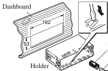
After inserting the holder into the dashboard, then select the appropriate tabs according to the thickness of the dashboard material and bend them. (Install as firmly as possible using the top and bottom tabs. To secure, bend the tabs 90 degrees.)
Rubber bush
Screw
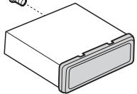
Removing the Unit
Pull out to remove the frame.
(When reattaching the frame, point the side with a groove downwards and attach it.)
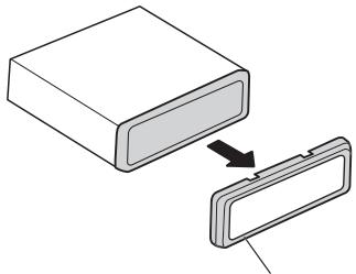
Frame
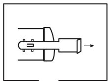
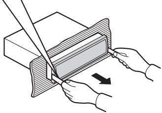
Insert the supplied extraction keys into the unit, as shown in the figure, until they click into place.
Keeping the keys pressed against the sides of the unit, pull the unit out.

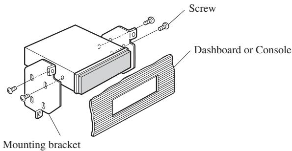
Installation using the screw holes on the side of the unit
- Fastening the unit to the factory radio mounting bracket.
Select a position where the screw holes of the bracket and the screw holes of the head unit become aligned (are fitted), and tighten the screws at 2 places on each side. Use either binding screws (5× 6mm) or flush surface screws (5× 6mm) , depending on the shape of the screw holes in the bracket.

CAUTION
- Do not cut the GPS aerial lead to shorten it or use an extension to make it longer. Altering the aerial cable could result in a short circuit.
Installation notes
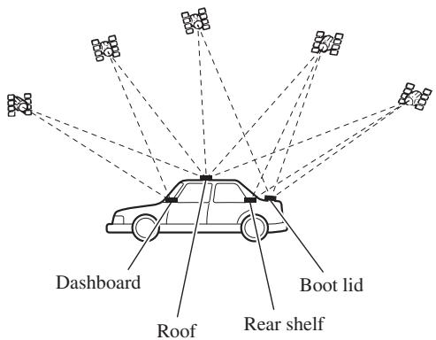
- The aerial should be installed on a level surface where radio waves will be blocked as little as possible. Radio waves cannot be received by the aerial if reception from the satellite is blocked. Installation on the vehicle roof or boot lid is recommended to enable best reception.
- When installing the GPS aerial inside the vehicle, be sure to use the metal sheet provided with your system. If this is not used, the reception sensitivity will be poor.
- Do not cut the accessory metal sheet. This would reduce the sensitivity of the GPS aerial.
- Take care not to pull the aerial lead when removing the GPS aerial. The magnet attached to the aerial is very powerful, and the lead may become detached.
- The GPS aerial is installed with a magnet. When installing the GPS aerial, be careful not to scratch the vehicle body.
- When installing the GPS aerial on the outside of the vehicle, always put it in the vehicle when going through an automatic vehicle wash. If it is left on the outside it may be knocked off and scratch the vehicle body.
- Do not paint the GPS aerial, as this may affect its performance.
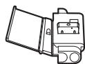
Parts supplied
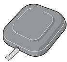
GPS aerial

Metal sheet

Clamp (5 pcs.)

Waterproof pad
When installing the aerial inside the vehicle (on the dashboard or rear shelf)
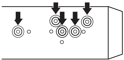
Affix the metal sheet on as level a surface as possible where the GPS aerial faces outside the window. Place the GPS aerial on the metal sheet. (The GPS aerial is fastened with its magnet.)
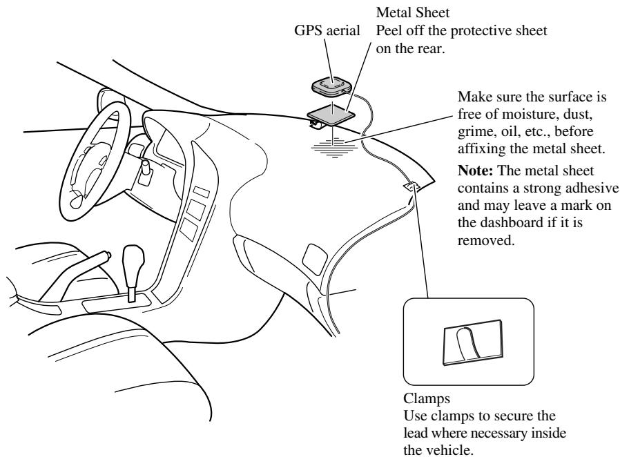
Note:
- When attaching the metal sheet, do not cut it into small pieces.
- Some models use window glass that does not allow signals from GPS satellites to pass through. On such models, install the GPS aerial on the outside of the vehicle.
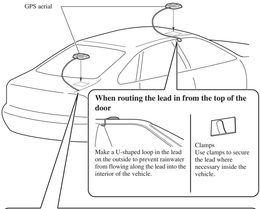
When installing the aerial outside the vehicle (on the body)
Put the GPS aerial in a position as level as possible, such as on the roof or boot lid. (The GPS aerial is fastened with a magnet.)
When routing the lead in from inside the boot
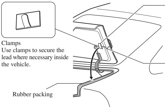
Waterproof pad
Make sure the waterproof pad contacts the top of the rubber packing.
Make a U-shaped loop in the lead outside the rubber packing to prevent rainwater from flowing along the lead into the interior of the vehicle.
Parts supplied
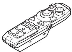
Remote control

(2 pcs.)
Alkaline battery
(UM-4, AAA, LR03 1.5 V)
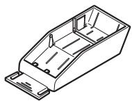
Holder
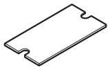
Double-sided tape (large)
Loading the batteries
Remove the battery cover, and insert two alkaline (UM-4, AAA, LR03, 1.5V) batteries.
For details, see "Hardware Manual".
CAUTION
- Take care to insert the batteries the right way round as shown by the + and - marks in the diagram.
- Do not mix new batteries with old.
- Do not mix different types of batteries. Even batteries of the same size may have different voltages.
- If the Remote Control will be out of use for a long period, remove the batteries.
- If a battery leaks, completely clean any liquid or deposits from the battery compartment before inserting new batteries.
- The supplied batteries cannot be recharged.
- We recommend using alkaline batteries as replacements.
- When disposing of used batteries, please comply with governmental regulations or environmental public institutional rules that apply in your country/area.
Remote control handling notes
- Always keep the remote control protected from direct sunlight or high temperatures. Leaving the remote control in places exposed to direct sunlight or high temperatures for long periods of time may cause deformation, discolouration or malfunction.
- Replace the batteries when the remote control's performance deteriorates.
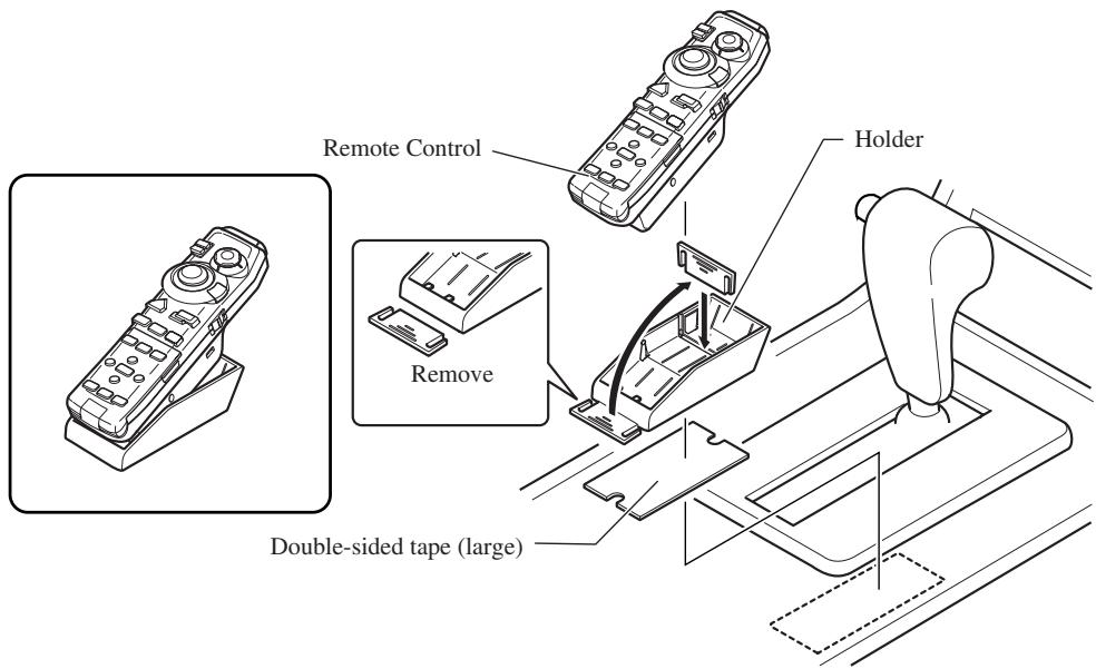
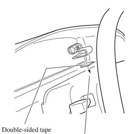
When installing with double-sided tape
Attach the Holder using the double-sided tape (large) included in the set.
When attaching horizontally
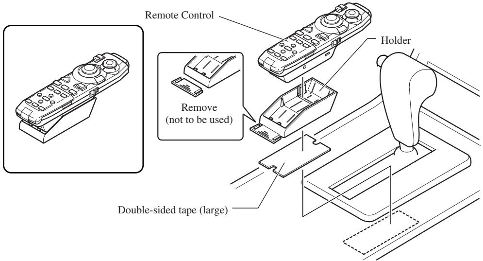
When attaching with elevated position
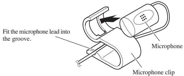
Installing the microphone
Installation notes
- Install the microphone in a position and orientation that will enable it to pick up the voice of the person operating the system.
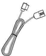
Parts supplied
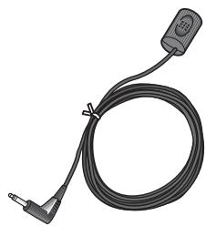
Microphone
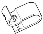
Microphone clip

Double-sided tape (small)

Clamp (5 pcs.)
When installing the microphone on the sun visor
1. Install the microphone on the microphone clip.
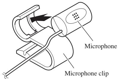
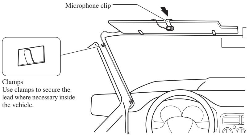
2. Install the microphone clip on the sun visor.
With the sun visor up, install the microphone clip. (Lowering the sun visor reduces the recognition rate for voice operations.)
When installing the microphone on the steering column
1. Install the microphone on the microphone clip.
2. Install the microphone clip on the steering column.
Install the microphone clip on the rear side of the steering column.
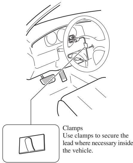
Clamps Use clamps to secure the lead where necessary inside the vehicle.

CAUTION
- It is extremely dangerous to allow the microphone lead to become wound around the steering column or gearstick. Be sure to install the unit in such a way that it will not obstruct driving.
1. Reconnecting the battery.
First, double-check that all connections are correct and that the unit is installed correctly. Reassemble all vehicle components that you previously removed. Then reconnect the negative (-) cable to the negative (-) terminal of the battery.
2. Start the engine.
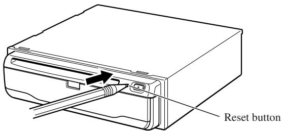
3. Press the reset button on the main unit.
Press the reset button on the main unit using a pointed object such as the point of a pen.
4. Set the navigation system.
Set the navigation system as explained in the "Operation Manual".

Bande adhesivedouble face (grande)
Insertion des piles
(INGRESSO SEGNALE RETROMARCIA)
Roze (RIJSNELHEIDSSIGNAAL)
Zekeringhouser(7,5A)
Zekeringweerstand
Zekeringweerstand
PIONEER ELECTRONICS (USA) INC.
P.O. Box 1760, Long Beach, California 90801, U.S.A.
TEL: (800) 421-1404
PIONEER EUROPE NV
Haven 1087, Keetberglaan 1, B-9120 Melsele, Belgium
TEL: (0) 3/570.05.11
PIONEER ELECTRONICS ASIACENTRE PTE. LTD.
253 Alexandra Road, #04-01, Singapore 159936
TEL: 65-472-1111
PIONEER ELECTRONICS AUSTRALIA PTY. LTD.
178-184 Boundary Road, Braeside, Victoria 3195, Australia
TEL: (03) 9586-6300
PIONEER ELECTRONICS OF CANADA, INC.
300 Allstate Parkway, Markham, Ontario L3R OP2, Canada
TEL: (905) 479-4411
PIONEER ELECTRONICS DE MEXICO, S.A. de C.V.
San Lorenzo 1009 3er. Piso Desp. 302
Col. Del Valle Mexico, D.F. C.P. 03100
TEL: 55-688-52-90
Published by Pioneer Corporation.
Copyright © 2002 by Pioneer Corporation.
All rights reserved.
Publication de Pioneer Corporation.
Copyright © 2002 Pioneer Corporation.