
AVH-P5700DVD - Car stereo PIONEER - Free user manual and instructions
Find the device manual for free AVH-P5700DVD PIONEER in PDF.
| Product Type | Multimedia car stereo with DVD player |
| Brand | PIONEER |
| Model | AVH-P5700DVD |
| Power Supply | 12 V DC (vehicle battery) |
| Operating Voltage | 12 V DC (negative ground) |
| Output Power | 50 W per channel (4 channels) |
| Speaker Impedance | 4 to 8 Ω |
| Dimensions (W × H × D) | 182 mm × 53 mm × 150 mm |
| Weight | 2 kg (approx.) |
| Max. Installation Angle | 30° from horizontal |
| Main Features | DVD/CD player, FM/AM radio tuner, auxiliary input, rear camera input, rear video output, iPod compatibility (with adapter), external amplifier control, subwoofer output |
| Audio Outputs | 4 channels front/rear + subwoofer output (mono) |
| Video Inputs | 1 auxiliary input (RCA), 1 rear camera input |
| iPod Compatibility | Yes (via CD-IB100 adapter) |
| Safety | DVD function disabled while driving; requires parking brake wire connection; professional installation recommended |
| Maintenance | Clean with a soft dry cloth; do not use solvents |
| Repairability | Spare parts available from authorised Pioneer service centres |
Frequently Asked Questions - AVH-P5700DVD PIONEER
User questions about AVH-P5700DVD PIONEER
0 question about this device. Answer the ones you know or ask your own.
Ask a new question about this device
Download the instructions for your Car stereo in PDF format for free! Find your manual AVH-P5700DVD - PIONEER and take your electronic device back in hand. On this page are published all the documents necessary for the use of your device. AVH-P5700DVD by PIONEER.
USER MANUAL AVH-P5700DVD PIONEER
This product conforms to new cord colors.
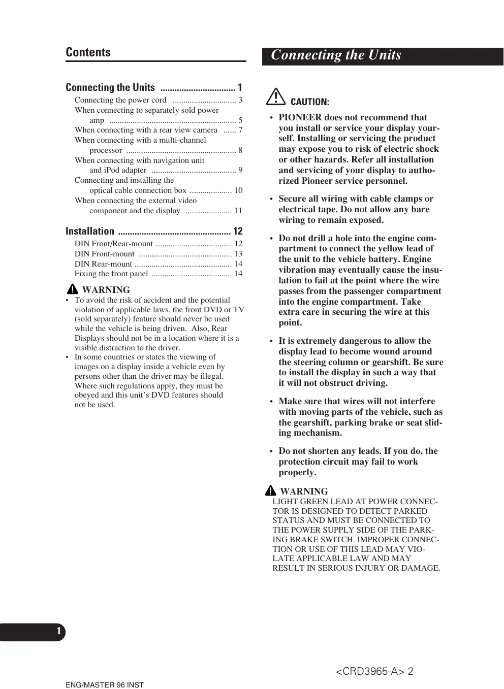
Connecting the Units 1
Connecting the power cord 3
When connecting to separately sold power amp 5
When connecting with a rear view camera ..... 7
When connecting with a multi-channel processor .... 8
When connecting with navigation unit and iPod adapter 9
Connecting and installing the optical cable connection box .... 10
When connecting the external video component and the display .... 11
Installation 12
DIN Front/Rear-mount 12
DIN Front-mount 13
DIN Rear-mount 14
Fixing the front panel 14
WARNING
- To avoid the risk of accident and the potential violation of applicable laws, the front DVD or TV (sold separately) feature should never be used while the vehicle is being driven. Also, Rear Displays should not be in a location where it is a visible distraction to the driver.
- In some countries or states the viewing of images on a display inside a vehicle even by persons other than the driver may be illegal. Where such regulations apply, they must be obeyed and this unit's DVD features should not be used.
CAUTION:
- PIONEER does not recommend that you install or service your display yourself. Installing or servicing the product may expose you to risk of electric shock or other hazards. Refer all installation and servicing of your display to authorized Pioneer service personnel.
- Secure all wiring with cable clamps or electrical tape. Do not allow any bare wiring to remain exposed.
- Do not drill a hole into the engine compartment to connect the yellow lead of the unit to the vehicle battery. Engine vibration may eventually cause the insulation to fail at the point where the wire passes from the passenger compartment into the engine compartment. Take extra care in securing the wire at this point.
- It is extremely dangerous to allow the display lead to become wound around the steering column or gearshift. Be sure to install the display in such a way that it will not obstruct driving.
- Make sure that wires will not interfere with moving parts of the vehicle, such as the gearshift, parking brake or seat sliding mechanism.
- Do not shorten any leads. If you do, the protection circuit may fail to work properly.
WARNING
LIGHT GREEN LEAD AT POWER CONNECTOR IS DESIGNED TO DETECT PARKED STATUS AND MUST BE CONNECTED TO THE POWER SUPPLY SIDE OF THE PARKING BRAKE SWITCH. IMPROPER CONNECTION OR USE OF THIS LEAD MAY VIO-LATE APPLICABLE LAW AND MAY RESULT IN SERIOUS INJURY OR DAMAGE.
Note:
- This unit is for vehicles with a 12-volt battery and negative grounding. Before installing it in a recreational vehicle, truck, or bus, check the battery voltage.
- To avoid shorts in the electrical system, be sure to disconnect the battery cable before beginning installation.
- Refer to the owner's manual for details on connecting the power amp and other units, then make connections correctly.
- Secure the wiring with cable clamps or adhesive tape. To protect the wiring, wrap adhesive tape around them where they lie against metal parts.
- Route and secure all wiring so it cannot touch any moving parts, such as the gear shift, handbrake and seat rails. Do not route wiring in places that get hot, such as near the heater outlet. If the insulation of the wiring melts or gets torn, there is a danger of the wiring short-circuiting to the vehicle body.
- Don't pass the yellow lead through a hole into the engine compartment to connect to the battery. This will damage the lead insulation and cause a very dangerous short.
- Do not shorten any leads. If you do, the protection circuit may fail to work when it should.
- Never feed power to other equipment by cutting the insulation of the power supply lead of the unit and tapping into the lead. The current capacity of the lead will be exceeded, causing overheating.
- When replacing the fuse, be sure to only use a fuse of the rating prescribed on the fuse holder.
- Since a unique BPTL circuit is employed, never wire so the speaker leads are directly grounded or the left and right speaker leads are common.
- If the RCA pin jack on the unit will not be used, do not remove the caps attached to the end of the connector.
- Speakers connected to this unit must be high-power with minimum rating of 50 W and impedance of 4 to 8 ohms. Connecting speakers with output and/or impedance values other than those noted here may result in the speakers catching fire, emitting smoke or becoming damaged.
-
When this product's source is switched ON, a control signal is output through the blue/white lead. Connect to an external power amp's system remote control or the car's Auto-antenna relay control terminal (max. 300 mA 12 V DC). If the car features a glass antenna, connect to the antenna booster power supply terminal.
-
When an external power amp is being used with this system, be sure not to connect the blue/white lead to the amp's power terminal. Likewise, do not connect the blue/white lead to the power terminal of the auto-antenna. Such connection could cause excessive current drain and malfunction.
- To avoid a short-circuit, cover the disconnected lead with insulating tape. Insulate the unused speaker leads without fail. There is a possibility of a short-circuit if the leads are not insulated.
- To prevent incorrect connection, the input side of the IP-BUS connector is blue, and the output side is black. Connect the connectors of the same colors correctly.
- This unit cannot be installed in a vehicle that does not have an ACC (accessory) position on the ignition switch. (Fig. 1)

text_image
OFF ACC ON STARTACC position

text_image
OFF ON STARTNo ACC position
Fig. 1
- The black lead is ground. Please ground this lead separately from the ground of high-current products such as power amps.
If you ground the products together and the ground becomes detached, there is a risk of damage to the products or fire.
- Cords for this product and those for other products may be different colors even if they have the same function. When connecting this product to another product, refer to the supplied manuals of both products and connect cords that have the same function.
Connecting the power cord

flowchart
graph TD
    A["IP-BUS cable"] --> B["Multi-CD player (sold separately)"]
    B --> C["Fuse holder"]
    C --> D["Fuse resistor"]
    D --> E["Black (ground) To vehicle (metal) body."]
    E --> F["ISO connector"]
    G["Cap (1*) When not using this terminal, do not remove the cap."] --> H["Yellow (3*) Back-up (or accessory)"]
    H --> I["Red (5*) Accessory (or back-up)"]
    I --> J["Blue Input (Blue)"]
    K["Connect leads of the same color to each other."] --> L["Fuse holder"]
    M["IP-BUS cable"] --> N["Multi-CD player (sold separately)"]
    O["Cap (1*) When not using this terminal, do not remove the cap."] --> P["Yellow (2*) To terminal always supplied with power regardless of ignition switch position."]
    Q["Red (4*) To electric terminal controlled by ignition switch (12 V DC) ON/OFF."] --> R["Fuse resistor"]
    S["Blue Input (Blue)"] --> T["Multi-CD player (sold separately)"]
    U["IP-BUS cable"] --> V["Multi-CD player (sold separately)"]
    W["Cap (1*) When not using this terminal, do not remove the cap."] --> X["Yellow (3*) Back-up (or accessory)"]
    Y["Red (5*) Accessory (or back-up)"] --> Z["Red (4*) To electric terminal controlled by ignition switch (12 V DC) ON/OFF."]
Note:
In some vehicles, the ISO connector may be divided into two. In this case, be sure to connect to both connectors.
When you connect the separately sold multi-channel processor (DEQ-P6600) to this unit, do not connect anything to the speaker leads and system remote control (blue/white).
Speaker leads
White: Front left ⊕
White/black: Front left ⊖
Gray: Front right ⊕
Gray/black: Front right ⊖
Green: Rear left ⊕ or Subwoofer ⊕
Green/black: Rear left ⊖ or Subwoofer ⊖
Violet: Rear right ⊕ or Subwoofer ⊕
Violet/black: Rear right ⊖ or Subwoofer ⊖

text_image
Antenna cable 15cmYellow/black
If you use a cellular telephone, connect it via the Audio Mute lead on the cellular telephone. If not, keep the Audio Mute lead free of any connections.
Violet/white
Of the two lead wires connected to the back lamp, connect the one in which the voltage changes when the gear shift is in the REVERSE (R) position. For details, refer to Fig.4

Connection method

- Clamp the lead.


- Clamp firmly with needle-nosed pliers.
Note:
- The position of the parking brake switch depends on the vehicle model. For details, consult the vehicle Owner's Manual or dealer.
Light green Used to detect the ON/OFF status of the parking brake. This lead must be connected to the power supply side of the parking brake switch.
Blue/white
To system control terminal of the power amp (max. 300 mA 12 V DC).

text_image
Blue/white (6*) Blue/white To Auto (max. 30)Blue/white (6\*)
Blue/white (7\*)
To Auto-antenna relay control terminal (max. 300 mA 12 V DC).
The pin position of the ISO connector will differ depending on the type of vehicle. Connect 6* and 7* when Pin 5 is an antenna control type. In another type of vehicle, never connect 6* and 7*.

text_image
Power supply side Ground side Parking brake switch lay control terminal DC).Fig. 2
When connecting to separately sold power amp

text_image
Subwoofer output or non fading output (SUBWOOFER OUTPUT or NON-FADING OUTPUT) 23 cm Front output (FRONT OUTPUT) 15 cm This product Blue/white To system control terminal of the power amp (max. 300 mA 12 V DC). Blue/white (6*) Blue/white (7*) To Auto-antenna relay control terminal (max. 300 mA 12 V DC).The pin position of the ISO connector will differ depending on the type of vehicle. Connect 6* and 7* when Pin 5 is an antenna control type. In another type of vehicle, never connect 6* and 7*.
When you connect the separately sold multi-channel processor (e.g. DEQ-P6600) to this unit, do not connect anything to the speaker leads and system remote control (blue/white).
Note:
When you connect the multi-channel processor to this unit, a separately sold power amp must be connected to the multi-channel processor.
Note:
Change the initial setting of this product (refer to the Operation Manual). The subwoofer output of this unit is monaural.

flowchart
graph TD
    A["Front speaker"] --> B["Subwoofer"]
    C["RCA cables (sold separately)"] --> D["Power amp (sold separately)"]
    D --> E["Power amp (sold separately)"]
    E --> F["Subwoofer"]
    G["System remote control"] --> H["Power amp (sold separately)"]
    H --> I["Power amp (sold separately)"]
    I --> J["Subwoofer"]
    K["Left"] --> L["Right"]
    M["Right"] --> N["Left"]
    O["Left"] --> P["Right"]
    Q["Left"] --> R["Right"]
    S["Left"] --> T["Right"]
    U["Left"] --> V["Right"]
    W["Left"] --> X["Right"]
    Y["Left"] --> Z["Right"]
    AA["Left"] --> AB["Right"]
    AC["Left"] --> AD["Right"]
    AE["Left"] --> AF["Right"]
    AG["Left"] --> AH["Right"]
    AI["Left"] --> AJ["Right"]
    AK["Left"] --> AL["Right"]
    AM["Left"] --> AN["Right"]
    AO["Left"] --> AP["Right"]
    AQ["Left"] --> AR["Right"]
    AS["Left"] --> AT["Right"]
    AU["Left"] --> AV["Right"]
    AW["Left"] --> AX["Right"]
    AY["Power amp (sold separately)"] --> AZ["Power amp (sold separately)"]
    style A fill:#f9f,stroke:#333
    style B fill:#ccf,stroke:#333
    style C fill:#cfc,stroke:#333
    style D fill:#fcc,stroke:#333
    style E fill:#cff,stroke:#333
    style F fill:#ffc,stroke:#333
    style G fill:#fcc,stroke:#333
    style H fill:#cff,stroke:#333
    style I fill:#ffc,stroke:#333
    style J fill:#fcc,stroke:#333
    style K fill:#fcc,stroke:#333
    style L fill:#fcc,stroke:#333
    style M fill:#fcc,stroke:#333
    style N fill:#fcc,stroke:#333
    style O fill:#fcc,stroke:#333
    style P fill:#fcc,stroke:#333
    style Q fill:#fcc,stroke:#333
    style R fill:#fcc,stroke:#333
    style S fill:#fcc,stroke:#333
    style T fill:#fcc,stroke:#333
    style U fill:#fcc,stroke:#333
    style V fill:#fcc,stroke:#333
    style W fill:#fcc,stroke:#333
    style X fill:#fcc,stroke:#333
    style Y fill:#fcc,stroke:#333
Fig. 3
When connecting with a rear view camera
When using this product with a rear view camera, automatic switching to video from a rear view camera when the gear shift is moved to REVERSE (R) position is possible. When connecting to a navigation unit, rear view mode also allows you to check what is behind you while driving. For details, refer to the Operation Manual.
WARNING
USE INPUT ONLY FOR REVERSE OR MIRROR IMAGE REAR VIEW CAMERA. OTHER USE MAY RESULT IN INJURY OR DAMAGE.
CAUTION
- The screen image may appear reversed.
- The rear view camera function is to use this product as an aid to keep an eye on trailers, or backing into a tight parking spot. Do not use this function for entertainment purposes.
- The object in rear view may appear closer or more distant than in reality.

flowchart
graph TD
    A["rear view camera"] --> B["Rear view camera in"]
    B --> C["To video output"]
    C --> D["Violet/white"]
    D --> E["8 m"]
    E --> F["Fuse resistor"]
    F --> G["Extension lead (supplied)"]
    G --> H["Violet/white"]
    style A fill:#f9f,stroke:#333
    style H fill:#ccf,stroke:#333
Connection method

1. Clamp the lead.


2. Clamp firmly with needle-nosed pliers.
Note:
- It is necessary to set B-CAM to ON in SET UP when connecting the rear view camera.
Fig. 4
When connecting with a multi-channel processor

flowchart
graph TD
    A["AV-BUS input (Blue)"] --> B["IP-BUS input (Blue)"]
    B --> C["Subwoofer output or non fading output (SUBWOOFER OUTPUT or NON-FADING OUTPUT)"]
    C --> D["Multi-channel processor (DEQ-P6600) (sold separately)"]
    D --> E["Video input"]
    E --> F["RCA cable (supplied with DVD player)"]
    D --> G["Optical cable (sold separately)"]
    G --> H["DVD Player (e.g. XDV-P9II or SDV-P7) (sold separately)"]
    H --> I["To video output (FRONT VIDEO OUTPUT)"]
    D --> J["IP-BUS cable (blue)"]
    J --> K["IP-BUS cable (supplied with TV tuner)"]
    K --> L["Hide-away TV tuner (e.g. GEX-P5700TV) (sold separately)"]
    L --> M["Multi-CD Player (sold separately)"]
    M --> N["Video output (black)"]
    N --> O["Black cable (simplified)"]
    O --> P["Optical cable (simplified)"]
    P --> Q["Subwoofer output or non fading output (SUBWOOFER OUTPUT or NON-FADING OUTPUT)"]
    Q --> R["Video input"]
    R --> S["Video input"]
    style A fill:#f9f,stroke:#333
    style B fill:#f9f,stroke:#333
    style C fill:#f9f,stroke:#333
    style D fill:#ccf,stroke:#333
    style E fill:#ccf,stroke:#333
    style F fill:#ccf,stroke:#333
    style G fill:#ccf,stroke:#333
    style H fill:#ccf,stroke:#333
    style I fill:#ccf,stroke:#333
    style J fill:#ccf,stroke:#333
    style K fill:#ccf,stroke:#333
    style L fill:#ccf,stroke:#333
    style M fill:#ccf,stroke:#333
    style N fill:#ccf,stroke:#333
    style O fill:#ccf,stroke:#333
    style P fill:#ccf,stroke:#333
    style Q fill:#ccf,stroke:#333
    style R fill:#ccf,stroke:#333
    style S fill:#ccf,stroke:#333
    style T fill:#ccf,stroke:#333
    style U fill:#ccf,stroke:#333
    style V fill:#ccf,stroke:#333
    style W fill:#ccf,stroke:#333
    style X fill:#ccf,stroke:#333
    style Y fill:#ccf,stroke:#333
    style Z fill:#ccf,stroke:#333
Fig. 5
When connecting with navigation unit and iPod adapter

text_image
26 pin cable input This unit 15 cm Yellow 26 pin cable (supplied with Navigation unit or Vehicle Dynamics Processor) IP-BUS input (Blue) 1.5 m Navigation unit (e.g. AVIC-800DVD) (sold separately) or Vehicle Dynamics Processor (e.g. AVG-VDP1) (sold separately) IP-BUS cable Black Blue iPod adapter (e.g. CD-IB100) iPod, iPod mini or iPod Photo Dock connector port Dock connector (Supplied with the iPod adapter) 1.5 m Multi-CD player (sold separately)It is necessary to set AV IN to M-DVD in SET UP when connecting to the DVD player.
Fig. 6
Connecting and installing the optical cable connection box
WARNING
- Avoid installing this unit in such a location where the operation of safety devices such as airbags is prevented by this unit. Otherwise, there is a danger of a fatal accident.
- Avoid installing this unit in such a location where the operation of the brake may be prevented. Otherwise, it may result in a traffic accident.
- Fix this unit securely with the velcro tape or lock tie. If this unit is loose, it disturbs driving stability, which may result in a traffic accident.
CAUTION
- Install this unit using only the parts supplied with this unit. If other parts are used, this unit may be damaged or could dismount itself, which leads to an accident or trouble.
- Do not install this unit near the doors where rainwater is likely to be spilled on the unit. Incursion of water into the unit may cause smoke or fire.
Connecting the optical cable
1. Connect the optical cable and ground lead to the main unit. (Fig. 7)
Connect the optical cable so that it does not protrude from the unit, as shown in the illustration. Fasten the ground lead to the protrusion on the back of the unit.

text_image
ScrewFig. 7
2. Connect the optical cable to the optical cable connection box. (Fig. 8)

text_image
Optical cableFig. 8
Installing the optical cable connection box
- When installing the optical cable connection box with the velcro tape. (Fig. 9)
Install the optical cable connection box using the velcro tape in the ample space of the console box.

text_image
Velcro tape (hard) Velcro tape (soft)Fig. 9
- When installing the optical cable connection box with the lock tie. (Fig. 10)
Wrap the optical cable and connection box with the protection tape and fasten with the power code using the lock tie.

text_image
Wrap with the protection tapeFasten with the lock tie
Fig. 10
When connecting the external video component and the display

flowchart
graph TD
    A["This unit"] --> B["Video input"]
    B --> C["Video output"]
    C --> D["Audio input"]
    D --> E["To video outputs"]
    E --> F["Video output"]
    F --> G["Multi-DVD Player (sold separately)"]
    G --> H["Audio output"]
    H --> I["Display with RCA input jacks"]
    I --> J["Video cable (sold separately)"]
    J --> K["To video input"]
    K --> L["Video output"]
    L --> M["External video component (sold separately)"]
    M --> N["Video cables (sold separately)"]
    N --> O["To video output"]
Fig. 11
- It is necessary to set AV INPUT to VIDEO in SET UP when connecting the external video component.
- It is necessary to set AV INPUT to M-DVD in SET UP when connecting a multi-DVD player.
When using a display connected to rear video output
This product's rear video output is for connection of a display to enable passengers in the rear seats to watch the DVD or Video CD.

WARNING:
- NEVER install the display in a location that enables the Driver to watch the DVD or Video CD while Driving.
Note:
- Before making a final installation of the unit, temporarily connect the wiring to confirm that the connections are correct and the system works properly.
- Use only the parts included with the unit to ensure proper installation. The use of unauthorized parts can cause malfunctions.
- Consult with your nearest dealer if installation requires the drilling of holes or other modifications of the vehicle.
- Install the unit where it does not get in the driver's way and cannot injure the passenger if there is a sudden stop, like an emergency stop.
- Do not install the display where it may (i) obstruct the driver's vision, (ii) impair the performance of any of the vehicle's operating systems or safety features, including air bags, hazard lamp buttons or (iii) impair the driver's ability to safely operate the vehicle.
- The semiconductor laser will be damaged if it overheats, so don't install the unit anywhere hot — for instance, near a heater outlet.
- If installation angle exceeds 30^ from horizontal, the unit might not give its optimum performance. (Fig. 12)

natural_image
Simple line drawing of a physics experiment setup with an inclined plane and a 30-degree angle indicator (no text or symbols beyond the angle label)Fig. 12
- The cords must not cover up the area shown in the figure below. This is necessary to allow the amplifies to radiate freely. (Fig. 13)

natural_image
Diagram of a computer rear panel showing internal components including fans, drive bays, and ports (no text or labels)Do not close this area.
Fig. 13
DIN Front/Rear-mount
This unit can be properly installed either from “Front” (conventional DIN Front-mount) or “Rear” (DIN Rear-mount installation, utilizing threaded screw holes at the sides of unit chassis). For details, refer to the following illustrated installation methods.
Before installing the unit
- Remove the frame and the holder. (Fig. 14)
Pull out to remove the frame and then loosen the screws (2 × 3 mm) to remove the holder. (When reattaching the frame, point the side with a groove downwards and attach it.)

text_image
Holder Screw (2 × 3 mm) FrameFig. 14
DIN Front-mount
Installation with the rubber bush
1. Decide the position of the side brackets. (Fig. 15)
When installing in a shallow space, change the position of side brackets. In this case, stick conceal tape on parts that protrude from the dashboard.

text_image
Side bracket Flush surface screw (5 × 6 mm) Conceal tapeFig. 15
2. Install the unit into the dashboard. (Fig. 16)
After inserting the holder into the dashboard, then select the appropriate tabs according to the thickness of the dashboard material and bend them.
(Install as firmly as possible using the top and bottom tabs. To secure, bend the tabs 90 degrees.)

text_image
Dashboard 182 53 Rubber bush Screw Holder Side bracket Screw (2 × 3 mm)• After installing the unit into the dashboard, reattach the frame.
Fig. 16
Installation using the screw holes on the side of the unit
- Fastening the unit to the factory radio mounting bracket. (Fig. 17) (Fig. 18) (Fig. 19)
Select a position where the screw holes of the bracket and the screw holes of this product become aligned (are fitted), and tighten the screws at 2 places on each side. Use any of binding screws (4 × 3 mm), binding screws (5 × 6 mm) or flush surface screws (5 × 6 mm), depending on the shape of the screw holes in the bracket.
*1 Use binding screws (4 × 3 mm) only.

natural_image
Isometric diagram of a rectangular electronic device with labeled ports and connectors (no text or symbols)Fig. 17
- When installing in a shallow space, use the following screw holes. In this case, stick conceal tape on parts that protrude from the dashboard.

text_image
Conceal tape *1 *1Fig. 18

text_image
Screw Factory radio mounting bracket Dashboard or ConsoleFig. 19
Fixing the front panel
If you do not operate the removing and attaching the front panel function, use the supplied fixing screws to fix the front panel to this unit.
- Fix the front panel to the unit using fixing screws after removing the front panel. (Fig. 20)

text_image
Fixing screwFig. 20
text_image
OFF ACC ON STARTPosición ACC

text_image
OFF ON STARTnatural_image
Technical line drawing of a mechanical assembly with a magnified inset showing internal components (no text or symbols)Fig. 2
natural_image
Diagram of an internal electronic device showing ports and connectors (no text or labels)text_image
Diagram of a device with labeled components and numbered indicators, showing a rectangular block with internal components and arrows indicating assembly or connection.Fig. 17
text_image
OFF ACC ON STARTACC-Position

text_image
OFF ON STARTKeine ACC-Position
Abb. 1
natural_image
Diagram of a computer internal structure showing drive, ports, and connectors (no text or labels)text_image
Technical diagram of a mechanical or electronic component with labeled parts and dimension indicatorsAbb. 17
text_image
OFF ACC ON STARTPosition ACC

text_image
OFF ON STARTAucune position ACC
Fig. 1
text_image
Bande Velcro (rigide) Bande Velcro (souple)Fig. 9
natural_image
Interior view of a computer drive bay showing ports, connectors, and ventilation duct (no text or labels)natural_image
Isometric diagram of a rectangular block with internal components and dimension indicators (no text or symbols)Fig. 17
text_image
OFF ACC ON STARTnatural_image
Technical line drawing of a mechanical assembly with a magnified inset showing internal components (no text or symbols)Fig. 2
natural_image
Diagram of an internal electronic device showing ports, connectors, and a speaker (no text or labels)text_image
Supporto Vite (2 × 3 mm) CorniceFig. 14
Montaggio anteriore a standard DIN
text_image
Technical diagram of a mechanical component with labeled parts and dimension indicatorsFig. 17
text_image
OFF ACC ON STARTACC stand

text_image
OFF ON STARTGeen ACC stand
Afb. 1
natural_image
Diagram of a computer rear panel showing internal components like CPU, memory, and drive slots (no text or labels)text_image
Diagram of a device with labeled components and directional arrows indicating assembly or movementAfb. 17
PIONEER ELECTRONICS (USA) INC.
P.O. Box 1540, Long Beach, California 90801-1540, U.S.A.
TEL: (800) 421-1404
PIONEER EUROPE NV
Haven 1087, Keetberglaan 1, B-9120 Melsele, Belgium
TEL: (0) 3/570.05.11
PIONEER ELECTRONICS ASIACENTRE PTE. LTD.
253 Alexandra Road, #04-01, Singapore 159936
TEL: 65-6472-7555
PIONEER ELECTRONICS AUSTRALIA PTY. LTD.
178-184 Boundary Road, Braeside, Victoria 3195, Australia
TEL: (03) 9586-6300
PIONEER ELECTRONICS OF CANADA, INC.
300 Allstate Parkway, Markham, Ontario L3R OP2, Canada
TEL: 1-877-283-5901
PIONEER ELECTRONICS DE MEXICO, S.A. de C.V.
Blvd.Manuel Avila Camacho 138 10 piso
Col.Lomas de Chapultepec, Mexico, D.F. 11000
TEL: 55-9178-4270
先鋒股份有限公司
Published by Pioneer Corporation.
Copyright © 2005 by Pioneer Corporation.
All rights reserved.
Publication de Pioneer Corporation.
Copyright © 2005 Pioneer Corporation.