
XENYX UFX1204 - Mixer BEHRINGER - Free user manual and instructions
Find the device manual for free XENYX UFX1204 BEHRINGER in PDF.

User questions about XENYX UFX1204 BEHRINGER
0 question about this device. Answer the ones you know or ask your own.
Ask a new question about this device
Download the instructions for your Mixer in PDF format for free! Find your manual XENYX UFX1204 - BEHRINGER and take your electronic device back in hand. On this page are published all the documents necessary for the use of your device. XENYX UFX1204 by BEHRINGER.
USER MANUAL XENYX UFX1204 BEHRINGER
Quick Start Guide
(Check out behringer.com for Full Manual)

natural_image
Black-and-white photo of a person in motion, possibly dancing or performing a gesture (no visible text or symbols)
natural_image
Close-up of a person wearing a jacket and dark clothing, with no visible text or symbols
natural_image
Black-and-white photo of a person operating a DJ audio workstation with multiple decoders (no visible text or symbols)
natural_image
Black-and-white photo of a concert stage with silhouetted audience and spotlights (no visible text or symbols)
natural_image
Crowd at a concert with raised hands and spotlights (no visible text or symbols)
natural_image
Black-and-white photo of a concert stage with dramatic lighting and silhouetted audience (no visible text or symbols)
natural_image
Black-and-white photo of a performer on stage with raised hand, surrounded by audience (no visible text or symbols)XENYX UFX1204
Premium 12-Input 4-Bus Mixer with 16x4 USB/FireWire Interface, 16-Track USB Recorder, XENYX Mic Preamps & Compressors, British EQs and Multi-FX Processor
2 XUNYXU-X'201 Quick Start Pulse 3
EN
ES
EN Important Safety Instructions

Terminal marked with this symbol carry electrical current of sufficient magnitude to constitute risk of electric shock. the only high quality professional speaker cables with 15" TS or twist lacking plugs are installed. All other installation or modification should be performed only by qualified personnel.
This symbol, wherever it appears, alerts you to the presence of uninsulated dangerous voltage inside the enclosure—voltage that may be sufficient to constitute a risk of shock.
This symbol, wherever it appears, alerts you to important operating and maintenance instructions in the accompanying literature. Please read the manual.
Caution To reduce the risk of electric shock, do not remove the top cover (or the rear section). No user serviceable parts inside. Refer servicing to qualified personnel.
Caution To reduce the risk of fire or electric shock, do not expose this appliance to rain and moisture. The apparatus shall not be exposed to dripping or splashing liquids and no objects filled with liquids, such as wares, shall be placed on the apparatus.
Caution These service instructions are for use by qualified service personnel only. To reduce the risk of electric shock do not perform any servicing other than that contained in the operation instructions. Repairs have to be performed by qualified service personnel.
-
Read these instructions.
-
Keep these instructions
-
Herdall warnings.
-
Followall instructions.
-
Do not use this apparatus near water.
-
Clean only with dry cloth.
-
Do not block any ventilation openings. Install in
accordance with the manufacturer's instructions.
-
Do not install near any heat sources such as radiators, heat registers, stoves, or other apparatus (including amplifiers) that produce heat.
-
Do not defeat the safety purpose of the polarized or grounding-type plug. A polarized plug has two blades with one wister than the other. A grounding-type plug has two blades and a third grounding prong. The wide blade or the third prong are provided for your safety. If the provided plug does not fit into your outlet, consult an electrician for replacement of the obsores outlet.
-
Protect the power cord from being walked on or pinched particularly at plugs, convenience receptacles, and the point where they eat from the apparatus.
-
Use only attachments/accessories specified by the manufacturer.

- Use only with the cart, stand, tripod, bracket, or table specified by the manufacturer, or sold with the apparatus. When a cart is used, use caution when moving the cart'apparatus combination to avoid
injury from tip-over.
-
Unplug this apparatus during lightning storms or when unused for long periods of time.
-
Refer all servicing to qualified service personnel. Servicing is required when the apparatus has been damaged in any way, such as power supply cord or plug in damaged, liquid has been spilled or objects have fallen into the apparatus, the apparatus has been exposed to rain or moisture, does not operate normally, or has been dropped.
-
The apparatus shall be connected to a MURS socket outlet with a protective earthing connection.
-
Where the MAFS plug or an appliance coupler is used as the disconnect device, the disconnect device shall remain readily operable.

LEGAL DISCLAIMER
TECHNICAL SPECIFICATIONS AND APPEARANCES ARE SUBJECT TO CHANGE WITHOUT NOTICE AND ACCURACY IS NOT GUARANTED. REHRINGER, KLARK, EIKIK, MUNA, BUGUERA, AND TURBSOUND ARE PART OF THE MUSIC GROUP (MUSIC-GROUP.COM). ALL TRADEMARKS ARE THE PROPERTY OF THEIR RESPECTIVE OWNERS. MUSIC GROUP ACCEPTS NO LIABILITY FOR ANY LOSS WHICH MAY BE SUPERFED BY ANY PERSON WHO RELIES EITHER WHOLLY OR IN PART UP ON ANY DESCRIPTION, PHOTOGRAPH OR STATEMENT CONTAINED HEREIN. COLORS AND SPECIFICATIONS MAY VARY FROM ACTUAL PRODUCT. MUSIC GROUP PRODUCTS ARE SOLD THROUGH AUTHORIZED FULLI-FILLERS AND RISSELLERS ONLY FULLI-ILLARDS AND RISSELLERS ARE NOT AGENTS OF MUSIC GROUP AND HAVE ABSOLUTELY NO AUTHORITY
TO BIND MUSIC GROUP BY ANY EXPRESS OR IMPLIED UNDERPARED OR REPRESENTATION. THIS MANUAL IS COPYRIGHTED, NO PART OF THIS MANUAL MAY BE REPRODUCED OR TRANSMITTED IN ANY FORM OR BY ANY MEANS, ELECTRONIC OR MECHANICAL, INCLUDING PHOTOCOPYING AND RECORDING OF ANY KIND, FOR ANY PURPOSE, WITHOUT THE EXPRESS WRITTEN PERMISSION OF MUSIC GROUP (P) LTD.
ALL RIGHTS RESERVED. © 2013 MUSK Group IP Ltd. Trident Chambers, Wickhams Cay, P.O. Box 146, Road Town, Tortola, British Virgin Islands.
LIMITED WARRANTY
For the applicable warranty terms and conditions and additional information regarding MUSIC Group's Limited Warranty, please see complete details online at www.music-group.com/warranty.
ES
RESERVADOS TOODS LOS DERECHOS. © 2013 MUSIC Group IP Ltd. Trident Chambers, Wickhams Cay, P.O. Box 146, Road Town, Tortola, British Virgin Islands
GARANTÍA LIMITADA
ALLERECHTE VORBERHALTER. © 2013 MUSIC Group IP Ltd. Tricent Chambers, Wickhams Coy, P.O. Box 146, Road Town, Tortola, British Virgin Islands
BESCHRÄNKTE GARANTIE
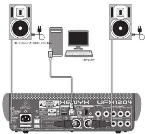
XENYX UFX1204 Hook-up
FN Step 1: Hook-Up
Paso 1: Conexión
ETR Etape 1 : Connexions
Schritt 1: Verkabelung
PT Passo 1: Conexões
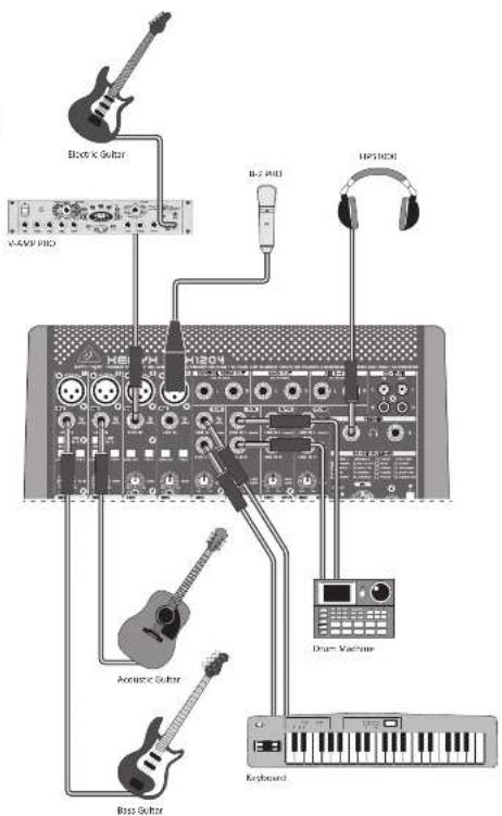
Project Studio root project Studio root
10 KENYK UH X1254
11 Quick Start Guide
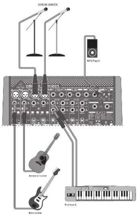
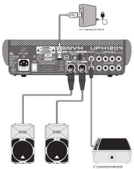
XENYX UFX1204 Hook-up
Step 1: Hook-Up
Paso 1: Conexión
Etape 1 : Connexions
Schritt 1: Verkabelung
PT Passo 1: Conexões
Lin Polysmae, var. van Klin Polysmae byzand
12 13 XUYXU XY201 Quick Start Guide
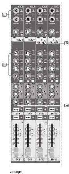
XENYX UFX1204 Controls

![[3-21] [7] [8] [9] [10] [11] [12] [13] 8.88 MAIN MIX Sands and Remun Controls](/content/2026/05/760549/images/4d70863c69670222f57a724e51ac6c1a1a2c3302fab838fe850b065309521e86.jpg)
52
XENYX UFX1204 Controls
Step 2: Controls
① XLR balanced input.
2. UBEU-7 input
3 LINE/HI-Z button (Channels 1 & 2 only). When HI-Z mode is engaged, you can plug your guitar or bass into this input without using an external direct (D.I.) box.
+48 V Phantom power is used for condenser microphones that require between 9 V DC and 48 V DC power to operate.
☐ LOW CUT button filters out frequencies below 80 Hz.
[6] GAIN knob adjusts the sensitivity of the MIC and LINE/HI-Z Inputs.
7 SEND lets you choose to route your input signal to FireWire/USB pre or post EQ.
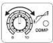
(3) COMPRESSOR knob adjusts the amount of compression effect on the channel.
☐ EQ knobs adjust the HIGH, MID, and LOW frequencies of the channel. Adjust the FREQ knob to select the specific frequency adjusted by the MID knob.
⑫ EQ button turns the EQ section on and off.
(1) AUX / FX knobs adjust how much of the channel's signal is sent to the AUX SEND jacks and/or the internal FX processor.
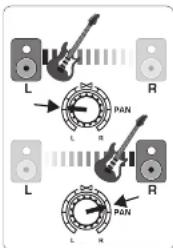
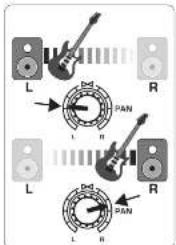
(12) PAN knob positions the channel's signal in the stereo field.
(16) MUTE button removes the channel from the MAIN MIX and sends it to the ALT 3-4 bus.
(14) SOLO button sends the channel signal to the solo bus (Solo in Place) or to the PFL bus (Pre-Fader Listen).
LEVEL METER shows the input signal level of the channel's input signal.
(16) CHANNEL FADER adjusts the channel volume.
⑬ LINE IN left and right input jacks for mono or stereo signals.
(14) LINE:FW 1-2 (3-4) button allows the signal from a computer to be routed via FireWire/USB to these channels and controlled by the EQ and AUX and fader functions.
NOTE: All FireWire (FW) routing switches work for USB connectivity to a computer and for the USB stand-alone mode depending on how you have the MODE selector switch (48) set.
12 4-band EQ for the stereo channels.
[24] BAL (ANCE) knob controls the relative volume of the left and right input signals before they are routed to the stereo main mix bus.
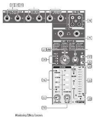
☑ CONTROL ROOM OUT jacks carry the summed effects and main mbr signals, as well as soloed channel signals.
☐ MAIN OUT jacks for connecting line level signal to powered speakers or external amplifier.
(20) ALT 3-4 OUT jacks for connecting line level signal of an alternate stereo mix to a recording device, powered speakers or external amplifier. Can also be used for subgrouping.
CD/TAPE IN and OUT for connecting a stereo source or for sending the main signal to an external recorder.
☐ PHONES jacks for connecting headphones.
[26] INPUT level meters display the signal input intensity going into the FX bus.
FX effect knob selects which effect is applied to the signal.
[36] EDIT knob adjusts the effect's main parameter.
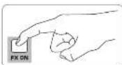
FX ON button turns the effect on and off.
(36) The TAP/SELECT button performs two functions. Hit the button several times in the tempo of the music piece to adapt the delay time of presets 9 and 15 or the modulation speed of presets 10-12. The Button will start flashing in the corresponding tempo. The TAP/SELECT button also changes the characteristic of the second parameter on presets 1-8, 13-14 and 16. By pressing the button you can toggle between two different values (light off/on) for the second parameter.
☐ PN/USB LED indicates the computer is connected (based on the selection switch on back panel).
☑ VU METER displays the MAIN OUTPUT signal level.
(3) MODE button determines whether the SOLD button operates in "Solo In Place" (button out) or "Pre-Fader Listen" (button In). PFL is preferred for gain setting purposes.
14 PHONES knob controls the volume level of the PHONES jacks.
☐ CONTROL RM knob controls the volume of the CONTROL ROOM OUT jacks.
☐ SOURCE monitoring select buttons
route the signal to either the CONTROL RM/PHONES jacks (left column)
or the MAIN MIX (right column).
PRE/POST fader select buttons for the AUX and FX SEND husses.
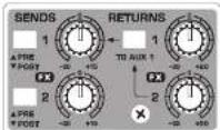
☐ AUX SEND 1-2 knobs adjust the level from send busses 1-2 (rear panel), internal FX bus (AUX 2 only), and FW 13-14 channels for recording (post knob).
Destination routing switch for AUX RETURN 2 (to MAIN bus or AUX SEND 1 bus).
(4) AUX RETURN 1-2 knobs adjust the level of AUX RETURN busses 1-2 (rear panel) or return signal from internal FX (AUX 2 only).
MUTE, SOLD, and output LEVEL knobs for ALT 3-4 bus.
TALKBACK MIC (Built-in), LEVEL knob [adjusts TALKBACK microphone volume], DESTINATION switches, and TALK button (press while talking).
16 TRACK USB DRIVE RECORDER/MIDI TRANSPORT CONTROL for use while connected to a computer via FireWire or USB as a MIDI Machine Control. Also used in STAND ALONE MODE for controlling the Internal USB recorder functions.
(24) MAIN MIX stereo fader adjusts the overall output of the mixer.
POWER ON turns the mixer on.
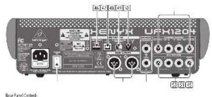
USB DRIVE jack for use with external USB hard disk drives (recommended) or thumb drives in STAND ALONE mode.
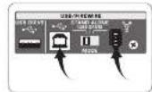
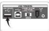
USB jack for connecting to a computer.
48 MODE selector switch.
[4] FireWire jacks for connecting to a computer.
☑ CHANNEL INSERTS allow you to connect external effects to the individual channels (1-4) PRE-FADER and PRE-EQ.
☐ MAIN OUTPUTS for sending MAIN MIX via balanced XLR cables.
AUX(LIARY) SENDS route the 2 auxiliary bus signals via balanced or unbalanced 14* cables.
53 AUX(LIARY) RETURNS allow you to bring a stereo effects signal routed from an AUX SEND jack, through a processor, back into the designated auxiliary bus. These inputs can also be used to connect additional line sources such as keyboards.
XENYX UFX1204 Controles
15 Paso 2: Controles
XENYX UFX1204 Controles
PT Passo 2: Controles
XENYX UFX1204 Getting started
Step 3: Getting started

Make sure the power to all devices is turned off.

Connect all appropriate power, audio and Fire/Wire/USB cables to the mixer.

Set all faders to the down position, PAN/BAL knobs centered and all other knobs (except EQ) all the way left.

Turn the mixer on.

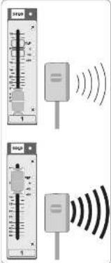
With the MAIN MIX fader, PHONES, CONTROL RM, and ALT 3-4 knobs all the way down, turn your PA system or monitors on.

Slowly raise the MAIN MIX fader, PHONES, CONTROL RM and ALT 3-4 knobs to 0 or the desired level.
See "Step 4: Gain Setting" for more information.

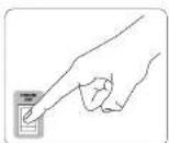
Adjust the level of connected microphones and instruments by raising each CHANNEL FADER.

Adjust the left-right position of a channel in the stereo field if necessary by turning the channel's P&I or BIL knob.

Adjust the COMP knob to add compression to an input if necessary.
Quick Start Guide

For live applications, adjust the overall output from the mixer to the power amp or powered speakers by raising the fader. If the CLIP LEDs on the light, lower the MAIN MDC fader.

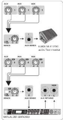
Use the channel AUX knobs and master AUX SEND knob to send the channel signals to an effects processor or stage connected to the AUX SEND jacks. If used route the signal back from the processor RETURN jacks.
flowchart
graph TD
    A["Input Channel 1"] --> B["Signal Processing Unit"]
    C["Input Channel 2"] --> B
    D["Input Channel 3"] --> B
    E["Input Channel 4"] --> B
    F["Input Channel 5"] --> G["Output Display"]
    H["Input Channel 6"] --> G
    I["Input Channel 7"] --> G
    J["Input Channel 8"] --> G
    K["Input Channel 9"] --> G
    L["Input Channel 10"] --> G
    M["Input Channel 11"] --> G
    N["Input Channel 12"] --> G
    O["Input Channel 13"] --> G
    P["Input Channel 14"] --> G
    Q["Input Channel 15"] --> G
    R["Input Channel 16"] --> G
    S["Input Channel 17"] --> G
    T["Input Channel 18"] --> G
    U["Input Channel 19"] --> G
    V["Input Channel 20"] --> G
    W["Input Channel 21"] --> G
    X["Input Channel 22"] --> G
    Y["Input Channel 23"] --> G
    Z["Input Channel 24"] --> G
    AA["Input Channel 25"] --> G
    AB["Input Channel 26"] --> G
    AC["Input Channel 27"] --> G
    AD["Input Channel 28"] --> G
    AE["Input Channel 29"] --> G
    AF["Input Channel 30"] --> G
    AG["Input Channel 31"] --> G
    AH["Input Channel 32"] --> G
    AI["Input Channel 33"] --> G
    AJ["Input Channel 34"] --> G
    AK["Input Channel 35"] --> G
    AL["Input Channel 36"] --> G
    AM["Input Channel 37"] --> G
    AN["Input Channel 38"] --> G
    AO["Input Channel 39"] --> G
    AP["Input Channel 40"] --> G
    AQ["Input Channel 41"] --> G
    AR["Input Channel 42"] --> G
    AS["Input Channel 43"] --> G
    AT["Input Channel 44"] --> G
    AU["Input Channel 45"] --> G
    AV["Input Channel 46"] --> G
    AW["Input Channel 47"] --> G
    AX["Input Channel 48"] --> G
    AY["OUTPUT"] --> AZ["OUTPUT"]
    AY --> BA["OUTPUT"]
    AY --> BB["OUTPUT"]
    AY --> BC["OUTPUT"]
    AY --> BD["OUTPUT"]
    AY --> BE["OUTPUT"]
    AY --> BF["OUTPUT"]
    AY --> BG["OUTPUT"]
    AY --> BH["OUTPUT"]
    AY --> BI["OUTPUT"]
26 XENYXUIX1254
Gain Setting Multi-FX Processor
FN Step 4: Gain Setting
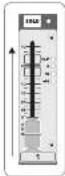
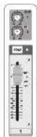
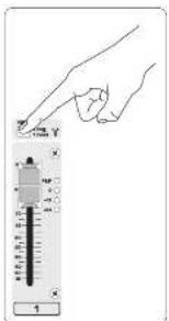
1 Press the Channel 1 SOLO button. Press the MODE button under the VU METER in the main section to allow the METER to operate in PFL (pre-fader listen) mode.
2 Sing, Speak, or play at a normal level through the microphone or instrument connected to Channel 1.
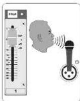
While singing or playing, turn Channel 1's GAIN knob. The VU METER will display the signal level. Set the GAIN so the loudest peaks reach O on the VU METER. Press the Channel 1 SOLO button again.
4 Repeat steps 1-3 for any other channels that will be used.
27 Quick Start Guide
Step 5: Multi-FX Processor
Your mixer has a built-in effects processor. Follow these steps to add effects to one or more channels.
1 Tum the FX knob up halfway on each channel you would like to add an effect to.
2 Turn the FX SEND and FX RETURN knobs to "0". You may adjust them later.
3 Make sure the FX ON button is pushed in.
4 Scroll through the effects by turning the FX knob.
5 Adjust the intensity of the effect turning the edit knob.

6 If using presets 1-8, 13-14, or 16, press the TAP/SELECT button to toggle between two different values (light off/on) for the second parameter. To adjust the delay time of presets 9 and 15, hit the TAP/SELECT button several times in the tempo of the music piece. Similarly, hit the TAP/SELECT button several times to adjust the modulation speed of presets 10-12. The button will start flashing in the corresponding tempo.
7 Readjust each channel's FX knob to make sure the right amount of effect is added.
28 XENYXUIX1254
29 Quick Start Guide
FireWire and USB recording Recording to USB drive in STAND-ALONE mode
Step 6: FireWire and USB recording
Your mixer is equipped with AD/DA converters, FireWire and USB connections for sending audio to and from your computer.
1 Make sure the drivers for the UFX1204 are loaded on your windows operating system (driver is not required for Mac US X operating system software).
2 Connect the mixer to the computer via FireWire or USB. Make sure you set the 3-way switch on the back panel of the mixer accordingly.
3 Select the UFX1204 inputs and outputs you'd like to use in your recording software.
4 Set your desired sample rate and bit depth from within your DAW (digital audio workstation) software.
5 Connect your microphones, instruments, and line level sources to the channel inputs. Each channel can be recorded pre or post EQ as its own mono or stereo track in your recording software. It is also possible to record the AUX sends on FireWire channels 13/14. The WALK mix can also be recorded on FireWire channels 15/15.
6 Arm the tracks in your recording software and record when ready.
Step 7: Recording to USB drive in STAND-ALONE mode
1 Make sure the STAND ALONE mode is selected on the back of the mixer (center position).
When a new USB drive is inserted for the first time, the mixer tests the writing speed of the drive to determine the audio quality. The outcome appears on the TRANSPORT CONTROL screen as "Lo" (16 bit) or "Hi" (24 bit). If the drive is too slow for recording, the display will show "SiO" after testing.
3 if your drive needs to be formatted, press and simultaneously on the TRANSPORT CONTROL until the display reads "Tor" (blinking). Push _to initiate formatting or _to abort.
4 To show the sample rate setting, push and hold the TIME REMARK button until the sample rate is displayed.
5 To change the sample rate to 44.1 MHz, push and hold TIME REMAIN until the sample rate appears and then
press □ while still holding TIME REMAIN.
6 To change the sample rate to 48 MHz, push TIME REMAIN until the sample rate appears and then press □ while holding TIME REMAIN.
7 With all your microphones, instruments, and source signals connected press the Button on the TRANSPORT CONTROL to create a new folder on the USB drive with the individual channels as files. Congratulations! You are now recording.
Press when finished.
The recordings are displayed on the
TRANSPORT CONTROL screen as
numbers (1-99).
9 To toggle between recording and playlist modes, press TIME REMAIN and at the same time for two seconds.
10 To listen or navigate through recordings you have made, you must be in recording mode. Playlist mode is ONLY for playing back WAV files you copied to your drive from a PC/Mac.
While in recording mode, press to hear what you just recorded. To return to the start, press the on the TRANSPORT CONTROL once.
Press twice to move to the previous recording.
Press to move to the start of the
next recording. Note: long push on the .mt will not fast forward or rewind within the track. The MAIN MIX recordings [tracks 15 and 16] will be played back in the control room section or on channel 11/12 when the FW 3-4 button is engaged.
11 To toggle between single playback and continuous playback mode (in playlist mode), long press
12 To delete the current song in recording mode, playback or recording must be stopped. Press and together. Press to complete deletion or to cancel.
13 IMPORTANT NOTE: the USB recorder only plays songs if they are away files with sample rates of 44.1 or 45.0 kHz from the folder labeled "MyWay", no subfolders are accepted.
30 KENYK UH X1254
Recording to USB drive in STAND-ALONE mode
Step 7: Recording to USB drive in STAND-ALONE mode
| Transport Control Feature Chart | |
| Show Remaining Time | Press TIME REMAIN short |
| Show Sampling Rate | Push and hold TIME REMAIN button until the sample rate is displayed |
| Select Sampling Rate 44.1 kHz | Push and hold TIME REMAIN until the sample rate appears and then press – will be still holding TIME REMAIN |
| Select Sampling Rate 48 kHz | Push TIME REMAIN until the sample rate appears and then press – will be still holding TIME REMAIN |
| Toggle PLAY <> PAUSE | Press PLAY (to start) > press PLAY (to packet) > press PLAY (to continue) > etc. |
| Toggle Recording Mode (e.g., '001') <> Playlist Mode (e.g., '001') | Push TIME REMAIN – for two seconds |
| Toggle Single Playback ("Pass") <> Continuous Playback ("COS") [only in Playlist mode] | Push PLAY for two seconds |
| FAT formatting the USB drive* | Press together STOP + Unknown seconds |
| Delete current song (in Recording Mask)* | Press together PLAY + Unknown seconds |
*ness A/AY to confirm /er/other subtests abc.
| Error Codes: | |
| DIP | Direct write recording. A summary of the total number of attempts will be displayed after recording up to 500s. |
| FSL | The system error. Incomitant the system or the drive. Other must be formatted by the UDP. |
| eFF-Is external USB drive is recognized or connected | |
| SLO | The connected USB drive has been specified as too slow, but recording will be possible. |
*In our 2016, we are a "Job-powered data base available in the power of the next three data points" (the second data point)
31 Quick Start Guide
Using the MIDI CONTROL Features
Step 8: Using the MIDI CONTROL Features
The TRANSPORT CONTROL section on the UFX1204 Can operate as a MIDI controller in one of two modes: STANDARD MIDI MODE or MACKIE CONTROL MODE.
1 The Mixer must be turned off.
To select STANDARD MIDI MODE, hold ☐, turn the power on, then release ☐ when "Std" shows up in the display.
To shell kinetic control mode, then when the power on, then release when "MAC" shows up in the display.
3 For STANDARD MIX MODE, map the transport controls in your recording software to the TRANSPORT CONTROL buttons on the UX1204. In MACKIE CONTROL MODE, set your recording software to follow the appropriate protocol.
Puesta en marcha
“Tateful, all you refer to the way of the home programs”


m = 311
[Non-Text]


![BEHRINGER XENYX UFX1204 - [Non-Text] - 3](/content/2026/05/760549/images/23c8fe361014d9054f70286207d871fbc2a855b0e119c2db6022aa14c7fe34bf.jpg)
Staat 185 Kies, anderer welleb anders. „Laufeltektur: er der, er der, der, der, der, der, der, der, der, der, der, der, der, der, der, der, der, der, der, der, der, der, der, der, der, der, der, der, der, der, der, der, der, der, der, der, der, der, der, der, der, der, der, der, der, der, der, der, der, der, der, der
Passo 5: Processador Multi-FX

In the case of the first time, we have been a second time.
The Ground Truth image displays a single, solid horizontal line. According to Rule 2 (UNDERSCORE & LINE RULES), this is a stylistic or background line, not a placeholder underscore. Therefore, the OCR result must ignore it and output nothing or only meaningful text. The provided OCR content is "____", which consists of four underscores. This is an incorrect interpretation of the line as a placeholder, violating the rule that stylistic lines must be ignored. The OCR has hallucinated underscores where none should exist based on the GT's visual context. Hence, the OCR result is inconsistent with the Ground Truth.

| Mono Inputs | |
| Microwave inputs (NFEV2 mix prompt) 4 | |
| Type | XLR, electronically balanced, discrete input circuit |
| MICE.L.N.1(20 Hz - 20 kHz) | |
| at 0.0 source resistance - 129 dB / 131 dB 4-weighted | |
| at 50.0 source resistance - 126 dB / 130 dB 4-weighted | |
| at 150.0 source resistance - 127 dB / 129 dB 4-weighted | |
| Frequency response | <10 Hz - 140 kHz / 1 dB |
| <10 Hz - 200 kHz / 3 dB | |
| Gain range + 10 dB to +60 dB | |
| Max. input level + 12 dB to + 10 dB gain | |
| Impedance suppress 2 dB to 80 dB balanced | |
| Signal-to-noise ratio | 110 dB A, weighted<10 dB to 0.52 dB gain |
| Distortion (THC to 100.005dB/s [20 dB in a 20 dB gain] | |
| Phantom power + 60 V, multichalt per mic channel | |
| H. 2 Input impedance | 1 MHz |
| Line Inputs | |
| Type | 3" TBS connector, balanced |
| Impedance 20 dB balanced, 10 dB unbalanced | |
| Gain range - 10 dB to + 10 dB | |
| Max. input level 20 dBu | |
| Stereo Inputs | |
| Type | 3" TBS connector, balanced |
| Impedance 20 dB balanced, 10 dB unbalanced | |
| Gain range - 20 dB to + 20 dB | |
| Max. input level +32 dBu | |
| CO Tape In | |
| Type | IICA connector |
| Impedance 10 dB | |
| Max. input level + 22 dBu | |
| EQ Mono Channels | |
| Low | 90 Hz / ±15 dB |
| Mid | 100 Hz / ±8 dB / + 15 dB |
| High | 12 MHz / ±15 dB |
| Low cut | 80 Hz / 18 dB oct |
| EQ Stereo Channels | |
| Low | 80 Hz / + 15 dB |
| Low mid | 100 Hz / + 15 dB |
| High mid | 3 dB / ±15 dB |
| High | 12 MHz / ±15 dB |
| Channel Inserts | |
| Type | 3" TBS connector, unbalanced |
| Max. input level +22 dBu | |
| Cronstalk | |
| Main fader closed | 90 dB |
| Channel mixed | 88 dB |
| Channel fader closed | 86 dB |
| Aux Sends | |
| Type | 3" TS connector, unbalanced |
| Impedance 120 dB | |
| Max. output level | +27 dBu |
| Aux Returns | |
| Type | N° TRS connector, balanced |
| Impedance 20 dB balanced, 10 kΩ unbalanced | |
| Max. input level +22 dBu | |
| Main Outputs | |
| Type | XLR and 1/4" TRS balanced |
| Impedance 240 Ω balanced, 120 Ω unbalanced | |
| Max. output level | +28 dBu |
| Control From Output | |
| Type | N° TRS connector, unbalanced |
| Impedance 120 Ω | |
| Max. output level | +22 dBu |
| Dual Phones Output | |
| Type | N° TRS connector, unbalanced |
| Max. output level | +22 dBu / 25 Ω - 300 mV @ 100 Ω |
| CD Tape Out | |
| Type | RCA connector |
| Impedance 1 kΩ | |
| Max. output level | +22 dBu |
| Effects | |
| Convertors | 26-bit Delta-Sigma, 125-times oversampling |
| Sampling rate | 48 kHz |
| FireWire/USB Interface | |
| Operation modes | FireWire 400 or USB 2.0 |
| Connectors | 6-pin FireWire 100 (IEEE139/AC), USB 2.0 type 0 |
| Convertors | 24 bit |
| Sample rate | 44.1kHz, 48 kHz, 88.2MHz, 96 kHz |
| Channel number | 16 x 3 in/out |
| Operating systems | Windows XP or higher, Max OS X |
| Low latency audio support | 600 (W/m), Compuable (Max) |
| Transport section: MIDI control | Standard MIDI mode (IC/none commands) or Mobile control mode |
| USB Recorder (Stand Alone Route) | |
| Connector | USB 2.0 (type A) |
| Storage device | External USB 2.0 hard-disk drive utilization depends on required power consumption) |
| Sample rate | 44.1kHz, 48 kHz |
| File format: MOV (uncompressed) | |
| File system FAT 16 / FAT 32 | |
| Number of recorded channels | 16 tracks installed as mono MOV video |
| Power Supply | |
| Main voltage | 100 ~ 240 V~, 50/65 Hz |
| Power consumption | 60W |
| Fuse (100 ~ 230 V~, 50/60 kHz) | 1.2A h 250 V |
| Main controller | Standard IEC receptacle |
| Physical Weight | |
| Dimensions (M x W x D) | 3.8 x 12.3 x 17.2" / 90 x 311 x 438 mm |
| Weight | 9.916 x 7.5 kg |
15pikaleinq
| Effect no. | Effect | EDIT Parameter 1 | TAP/SELECT Parameter 2 | TAP/SELECT LEO |
| 1 | CATHERMAL | Reverse time | Brilliance | affion |
| 2 | CONJINT | Reverse time | Brilliance | affion |
| 3 | CLUB | Reverse time | Brilliance | affion |
| 4 | CHUMBER | Reverse time | Brilliance | affion |
| 5 | GOLD PLAY | Reverse time | Brilliance | affion |
| 6 | GOLD BUY | Reverse time | Brilliance | affion |
| 7 | REVERSE | Reverse time | Brilliance | affion |
| 8 | AMEREFECT | Room size | Brilliance | affion |
| 9 | BILLY | No. of responses | Time interval TAP | flashing (RPM temp) |
| 10 | CHORUS | Intensity | Tempo TAP | flashing (temp) |
| 11 | FLUERF | Intensity | Tempo TAP | flashing (temp) |
| 12 | PHASER | Intensity | Tempo TAP | flashing (temp) |
| 13 | RECTARY | Intensity | Tempo | offion |
| 14 | PITCHY FLIT | Semi lone steps H+/LTV | Balance | offion |
| 15 | BILLY BUY | Delay vs. reverse ratio | Time interval TAP | flashing (RPM temp) |
| 16 | CHORD'S REV | Corrug vs. reverse ratio | Reverse time | offion |
Increase, tax and G&A changes or cycle inc. registered in the U.S. and other countries. Medical equipment manufacturer of Slovak Corporation (the United States and other countries) includes a general market value of 10,000 million
EN Other important information
ES
EN Important information
- Register online. Please register your new MUSIC Group equipment right after you purchase it by visiting behinger.com. Registering your purchase using our simple online form helps us to process your repair claims more quickly and efficiently. Also, read the terms and conditions of our warranty, if applicable.
FR
- Malfunction. Should your MUSIC Group Author and Reseller not be located in your vicinity, you may contact the MUSIC Group Authorized Fuller for your country listed under "Support" at behinger.com. Should your country not be listed, please check if your problem can be dealt with by our "Online Support" which may also be found under "Support" at behinger.com. Alternatively, please submit an online warranty claim at behinger.com BEFORE returning the product.
DE
- Power Connections. Before plugging the unit into a power socket, please make sure you are using the correct mains voltage for your particular model. Equity fuses must be replaced with fuses of the same type and rating without corruption.
PT
FR Informations importantes
Responsible Party Name: MUSIC Group Services US Inc.
Address: 18912 North Creek Parkway, Suite 200 Bothell, WA 98011, USA
Phone: Fax No.: Phone: +1 425 672 0816
Fax: +1 425 673 7647
XENYX UFX1204
complies with the FCC rules as mentioned in the following paragraph:
This equipment has been tested and found to comply with the limits for a Class B digital device, pursuant to part 15 of the FCC Rules. These limits are designed to provide receivable protection against harmful interference in a residential installation. This equipment generates, uses and can radiate radio frequency energy and, if not installed and used in accordance with the instructions, may cause harmful interference to radio communications. However, there is no guarantee that interference will not occur in a particular installation. If this equipment does cause harmful interference to radio or television reception, which can be determined by turning the equipment off and on, the user is encouraged to try to correct the interference by one or more of the following measures:
• Recipient or relocate the receiving antenna
• Increase the separation between the equipment and receiver
- Connect the equipment into an outlet on a circuit different from that to which the receiver is connected
• Consult the dealer or an experienced radio/TV technician for help
This device complies with Part 15 of the FCC rules. Operation is subject to the following two conditions:
(1) this device may not cause harmful interference, and (2) this device must accept any interference received, including interference that may cause undesired operation.
Important information:
Changes or modifications to the equipment not expressly approved by MUSX Group can void the user's authority to use the equipment.
Quick Start Guide
71
EN
ES
FR
DE
PT

natural_image
Black-and-white photo of a smiling woman making a hand gesture with both hands (no text or symbols visible)We Hear You