
XENYX QX2222USB - Mixer BEHRINGER - Free user manual and instructions
Find the device manual for free XENYX QX2222USB BEHRINGER in PDF.


| Product type | Mixing console |
| Brand | Behringer |
| Model | XENYX QX2222USB |
| Number of inputs | 16 (8 mono + 4 stereo) |
| Power supply | 100-240 V~, 50/60 Hz, 30 W |
| Fuse | T 1.6A H 250 V |
| Dimensions (W x D x H) | 430 x 370 x 90 mm |
| Weight | 4.3 kg |
| Equalizer | 3-band semi-parametric (Low, Mid, High) + 4-band on stereo channels |
| Compressor | Built-in on each mono channel |
| Effects processor | 24-bit, 100 presets |
| USB input | Yes, for PC connection and wireless microphone receiver |
| Phantom power | +48 V switchable on inputs 3-8 (Jack/XLR) |
| Main outputs | 2 x balanced XLR, 2 x balanced 6.35 mm jack |
| Auxiliary outputs (AUX) | 3 sends and 2 returns (6.35 mm jack) |
| Headphone outputs | 1 x stereo 6.35 mm jack |
| VU meter | 12 segments (LED) |
| Maintenance and cleaning | Clean with a dry cloth; do not use solvents |
| Safety | Do not open, do not expose to water or moisture; unplug during storms |
| Spare parts and repairability | Repair only by a qualified professional; no user-serviceable parts |
| Included accessories | Power cable, user manual |
Frequently Asked Questions - XENYX QX2222USB BEHRINGER
User questions about XENYX QX2222USB BEHRINGER
0 question about this device. Answer the ones you know or ask your own.
Ask a new question about this device
Download the instructions for your Mixer in PDF format for free! Find your manual XENYX QX2222USB - BEHRINGER and take your electronic device back in hand. On this page are published all the documents necessary for the use of your device. XENYX QX2222USB by BEHRINGER.
USER MANUAL XENYX QX2222USB BEHRINGER
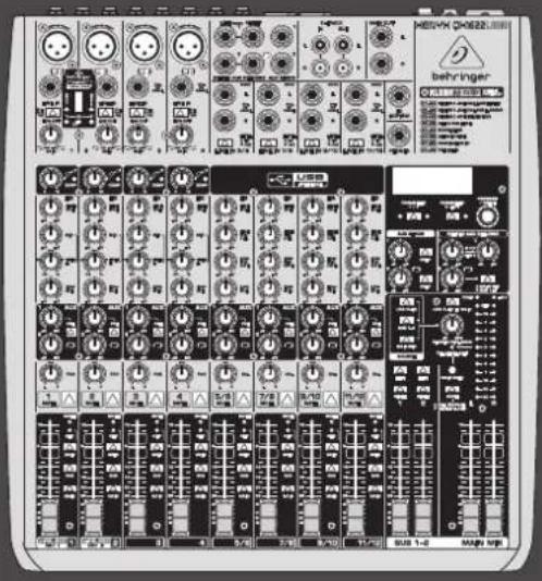
Quick Start Guide
(Check out behringer.com for Full Manual)

natural_image
Black-and-white collage of eight black-and-white photos showing a musician performing on stage, music equipment, and a concert with raised hands (no visible text or symbols)XENYX
QX2222USB/QX1622 USB
Premium 22/16-Input 2/2-Bus Mixer with XENYX Mic Preamps & Compressors, KLARK TEKNIK Multi-FX Processor, Wireless Option and USB/Audio Interface
2 XLNYX OX2ZZ2LS8/OX16ZZ2LS8 Quick Start Guide 3
EN
ES
EN Important Safety Instructions
Terminal marked with this symbol carry electrical current of sufficient magnitude to constitute risk of electric shock. the only high quality professional speaker cables with 15" TS or twist lacking plugs are installed. All other installation or modification should be performed only by qualified personnel.
This symbol, wherever it appears, alerts you to the presence of uninsulated dangerous voltage inside the enclosure—voltage that may be sufficient to constitute a risk of shock.
This symbol, wherever it appears, alerts you to important operating and maintenance instructions in the accompanying literature. Please read the manual.
Caution To reduce the risk of electric shock, do not remove the top cover (or the rear section). No user serviceable parts inside. Refer servicing to qualified personnel.
Caution To reduce the risk of fire or electric shock, do not expose this appliance to rain and moisture. The apparatus shall not be exposed to dripping or splashing liquids and no objects filled with liquids, such as wares, shall be plated on the apparatus.
Caution These service instructions are for use by qualified service personnel only. To reduce the risk of electric shock do not perform any servicing other than that contained in the operation instructions. Repairs have to be performed by qualified service personnel.
-
Read these instructions.
-
Keep these instructions
-
Herdall warnings.
-
Followall instructions.
-
Do not use this apparatus near water.
-
Clean only with dry cloth.
-
Do not block any ventilation openings. Install in
accordance with the manufacturer's instructions.
-
Do not install near any heat sources such as radiators, heat registers, stoves, or other apparatus (including amplifiers) that produce heat.
-
Do not defeat the safety purpose of the polarized or grounding-type plug. A polarized plug has two blades with one wister than the other. A grounding-type plug has two blades and a third grounding prong. The wide blade or the third prong are provided for your safety. If the provided plug does not fit into your outlet, consult an electrician for replacement of the obsores outlet.
-
Protect the power cord from being walked on or pinched particularly at plugs, convenience receptacles, and the point where they eat from the apparatus.
-
Use only attachments/accessories specified by the manufacturer.

- Use only with the cart, stand, tripod, bracket, or table specified by the manufacturer, or sold with the apparatus. When a cart is used, use caution when moving the cart'apparatus combination to avoid
injury from tip-over.
-
Unplug this apparatus during lightning storms or when unused for long periods of time.
-
Refer all servicing to qualified service personnel. Servicing is required when the apparatus has been damaged in any way, such as power supply cord or plug in damaged, liquid has been spilled or objects have fallen into the apparatus, the apparatus has been exposed to rain or moisture, does not operate normally, or has been dropped.
-
The apparatus shall be connected to a MUNS socket outlet with a protective earthing connection.
-
Where the MAFS plug or an appliance coupler is used as the disconnect device, the disconnect device shall remain readily operable.

LEGAL DISCLAIMER
TECHNICAL SPECIFICATIONS AND APPEARANCES ARE SUBJECT TO CHANGE WITHOUT NOTICE AND ACCURACY IS NOT GUARANTED. REHRINGER, KLARK, EIKIK, MUNA, BUGUERA, AND TURBSOUND ARE PART OF THE MUSIC GROUP (MUSIC-GROUP.COM). ALL TRADEMARKS ARE THE PROPERTY OF THEIR RESPECTIVE OWNERS. MUSIC GROUP ACCEPTS NO LIABILITY FOR ANY LOSS WHICH MAY BE SUPERFED BY ANY PERSON WHO RELIES EITHER WHOLLY OR IN PART UP ON ANY DESCRIPTION, PHOTOGRAPH OR STATEMENT CONTAINED HEREIN. COLORS AND SPECIFICATIONS MAY VARY FROM ACTUAL PRODUCT. MUSIC GROUP PRODUCTS ARE SOLD THROUGH AUTHORIZED FULLI-FILLERS AND RISSELLERS ONLY FULLI-ILLARDS AND RISSELLERS ARE NOT AGENTS OF MUSIC GROUP AND HAVE ABSOLUTELY NO AUTHORITY
TO BIND MUSIC GROUP BY ANY EXPRESS OR IMPLIED UNDERPARED OR REPRESENTATION. THIS MANUAL IS COPYRIGHTED, NO PART OF THIS MANUAL MAY BE REPRODUCED OR TRANSMITTED IN ANY FORM OR BY ANY MEANS, ELECTRONIC OR MECHANICAL, INCLUDING PHOTOCOPYING AND RECORDING OF ANY KIND, FOR ANY PURPOSE, WITHOUT THE EXPRESS WRITTEN PERMISSION OF MUSIC GROUP (P) LTD.
ALL RIGHTS RESERVED. © 2013 MUSK Group IP Ltd. Trident Chambers, Wickhams Cay, P.O. Box 146, Road Town, Tortola, British Virgin Islands.
LIMITED WARRANTY
For the applicable warranty terms and conditions and additional information regarding MUSIC Group's Limited Warranty, please see complete details online at www.music-group.com/warranty.
ES
RESERVADOS TOODS LOS DERECHOS. © 2013 MUSIC Group IP Ltd. Trident Chambers, Wickhams Cay, P.O. Box 146, Road Town, Tortola, British Virgin Islands
GARANTÍA LIMITADA
© 2013 MUSK Group IP Ltd.
Trident Chambers, Wickhams Cay, P.O. Box 146,
GARANTIE LIMITÉE
© 2013 MUSIC Group IP Ltd.
The company, the company, is
BESCHRÄNKTE GARANTIE
In the case of the present study, the results of the present study are presented in Table 1. The results of the present study are presented in Table 2.
10 11XENYX QX2222USB/QX1622USB Quick Start Guide
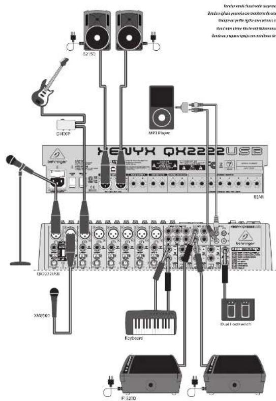
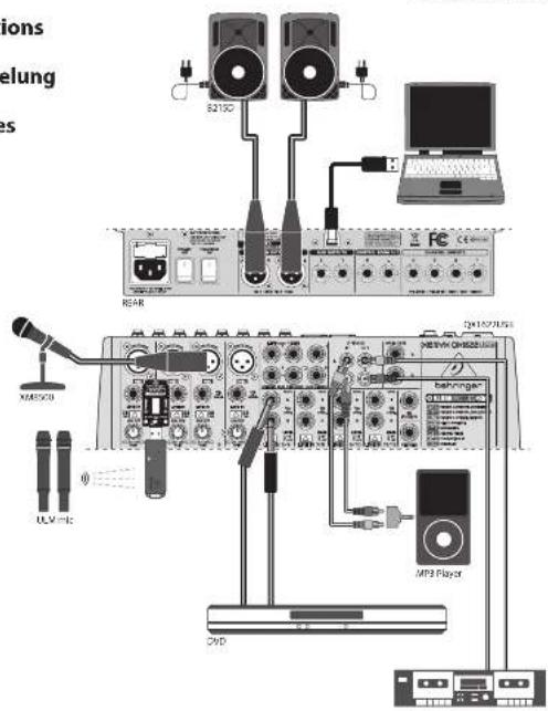
XENYX QX2222USB/QX1622USB Hook-up
Step 1: Hook-Up
Es Paso 1: Conexión
Etape 1 : Connexions
Schritt 1: Verkabelung
PT Passo 1: Conexões
Anima/natiwalepantala Anastalis strogale/natiwale Anastalis cennemak/natiwale Anima/Kitlerele-Anastalis presenta/bpresente/nitlerele
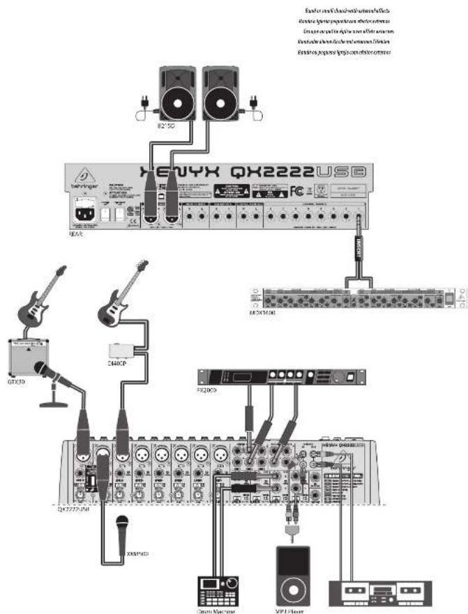
12 13XLNX QX2220S8/QX16220S8 Quick Start Guide
XENYX QX2222USB/QX1622USB Controls
Step 2: Controls
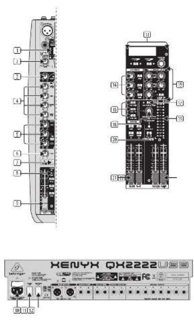
USB wireless input accepts a USB receiver for use with BEHRINGER ULM wireless microphones.
(2) GAIN knob adjusts the sensitivity of the MIC and/or LINE inputs.
COMP knob adjusts the amount of compression effect on the channel.
4 EQ knobs adjust the high, mid and low frequencies of the channel. Adjust the FREQ knob to select the specific frequency adjusted by the MID knob.
5 AUX knobs adjust how much of the channel's signal routes to the AUX SEND jacks. Press the PRE button when routing the signal to a stage monitor. Use the FX knob to send the channel's signal to the internal multi-FX processor.
[6] PAN/BAL knob positions the channel in the stereo field.
MUTE button mutes the channel.
CLIP LED lights when the channel signal overloads.
☐ CHANNEL FADER adjusts the channel volume.
flowchart
graph TD
    A["Central Device"] --> B["SLO-1-C"]
    A --> C["MADS-80K"]
    A --> D["SLO-1-C"]
    A --> E["SLO-1-C"]
    A --> F["SLO-1-C"]
    A --> G["SLO-1-C"]
    A --> H["SLO-1-C"]
    A --> I["SLO-1-C"]
    A --> J["SLO-1-C"]
    A --> K["SLO-1-C"]
    A --> L["SLO-1-C"]
    A --> M["SLO-1-C"]
    A --> N["SLO-1-C"]
    A --> O["SLO-1-C"]
    A --> P["SLO-1-C"]
    A --> Q["SLO-1-C"]
    A --> R["SLO-1-C"]
    A --> S["SLO-1-C"]
    A --> T["SLO-1-C"]
    A --> U["SLO-1-C"]
    A --> V["SLO-1-C"]
    A --> W["SLO-1-C"]
    A --> X["SLO-1-C"]
    A --> Y["SLO-1-C"]
    A --> Z["SLO-1-C"]
    A --> AA["SLO-1-C"]
    A --> AB["SLO-1-C"]
    A --> AC["SLO-1-C"]
    A --> AD["SLO-1-C"]
    A --> AE["SLO-1-C"]
    A --> AF["SLO-1-C"]
    A --> AG["SLO-1-C"]
    A --> AH["SLO-1-C"]
    A --> AI["SLO-1-C"]
    A --> AJ["SLO-1-C"]
    A --> AK["SLO-1-C"]
    A --> AL["SLO-1-C"]
    A --> AM["SLO-1-C"]
    A --> AN["SLO-1-C"]
    A --> AO["SLO-1-C"]
    A --> AP["SLO-1-C"]
    A --> AQ["SLO-1-C"]
    A --> AR["SLO-1-C"]
    A --> AS["SLO-1-C"]
    A --> AT["SLO-1-C"]
    A --> AU["SLO-1-C"]
    A --> AV["SLO-1-C"]
    A --> AW["SLO-1-C"]
    A --> AX["SLO-1-C"]
    A --> AY["SLO-1-C"]
    A --> AZ["SLO-1-C"]
    A --> BA["SLO-1-C"]
    A --> BB["SLO-1-C"]
    A --> BC["SLO-1-C"]
    A --> BD["SLO-1-C"]
    A --> BE["SLO-1-C"]
    A --> BF["SLO-1-C"]
    A --> BG["SLO-1-C"]
    A --> BH["SLO-1-C"]
    A --> BI["SLO-1-C"]
    A --> BJ["SLO-1-C"]
    A --> BK["SLO-1-C"]
    A --> BL["SLO-1-C"]
    A --> BM["SLO-1-C"]
    A --> BN["SLO-1-C"]
    A --> BO["SLO-1-C"]
    A --> BP["SLO-1-C"]
    A --> BQ["SLO-1-C"]
    A --> BR["SLO-1-C"]
    A --> BS["SLO-1-C"]
    A --> BT["SLO-1-C"]
    A --> BU["SLO-1-C"]
    A --> BV["SLO-1-C"]
    A --> BW["SLO-1-C"]
    A --> BX["SLO-1-C"]
    A --> BY["SLO-1-C"]
    A --> BZ["SLO-1-C"]
    A --> CA["SLO-1-C"]
    A --> CB["SLO-1-C"]
    A --> CC["SLO-1-C"]
    A --> CD["SLO-1-C"]
    A --> CE["SLO-1-C"]
    A --> CF["SLO-1-C"]
    A --> CG["SLO-1-C"]
    A --> CH["SLO-1-C"]
    A --> CI["SLO-1-C"]
    A --> CJ["SLO-1-C"]
    A --> CK["SLO-1-C"]
    A --> CL["SLO-1-C"]
    A --> CM["SLO-1-C"]
    A --> CN["SLO-1-C"]
    A --> CO["SLO-1-C"]
    A --> CP["SLO-1-C"]
    A --> CQ["SLO-1-C"]
    A --> CR["SLO-1-C"]
    A --> CS["SLO-1-C"]
    A --> CT["SLO-1-C"]
    A --> CU["SLO-1-C"]
    A --> CV["SLO-1-C"]
    A --> CW["SLO-1-C"]
    A --> CX["T-SLO-1-C"]
AC IN accepts the included power cable for connection to a mains outlet.
① POWER ON switch turns the mixer on and off.
PHANTOM ON switch sends 48 V to the XLR inputs for use with condenser microphones.
☐ MULTI-FX PROCESSOR adds a selected sound effect to any channels whose FX knob is turned up. See the Multi-FX Processor section for details.
☐ AUX SENDS adjust the amount of signal sent to a monitor speaker or external effects processor via the AUX SEND Jacks.
[16] AUX RETURNS adjust the amount of signal returning from an external effects processor that is included in the main mix. Use the TO AUX SEND knob(s) to include the effects signal in your monitor mix as well.
SOURCE buttons route the USB/2-TR, SUB, and MAIN MIX to the PHONES and CONTROL ROOM jacks.
USB/2-TR TO MAIN button routes the USB and 2-TRACK signal to the MAIN MID.
[16] PHONES/CTRL ROOM knob adjusts the headphone or studio monitor volume.
19 VU METER displays the MAIN OUTPUT signal level.
☒ MODE button determines whether the channel's SOLO button operates as 'Solo In Place' (button out) or 'Pre-Fader Listen' (button in). PFL is preferred for gain setting purposes.
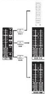
☑ SUB faders adjust the output of the
SUB OUTPUT jacks. Use the LEFT/RIGHT
buttons to assign the SUB signal to the left
and/or right MAIN MIX.
MAIN MIX faders adjust the overall output of the mixer.
14 15XLNYX QX2ZZZUS8/QX16ZZUS8 Quick Start Guide
XENYX QX2222USB/QX1622USB Controls
15 Paso 2: Controles
XENYX QX2222USB/QX1622USB Getting started
Step 3: Getting started
natural_image
Front view of a black industrial control panel with multiple buttons and indicator lights (no visible text or labels)1 Make sure the power to all devices is turned off
2 Connect all the appropriate power, audio and USB cables to the mixer.
3 Set all controls as shown above (EQ and PHL/BIL centered, all others down/off).
5 Set the GAIN for each channel. See the Gain Setting section for details.
6 With the MAIN MIX faders and PHONES/CTRL ROOM knob all the way down, turn your PA system or powered monitors on.
7 Slowly raise the MAIN MIX facers or PHONES/CTRL ROOM knob to desired level.
8 Press the MAIN button on each channel to assign the channel to the MAIN MIX.
9 In: Adjust the relative level of various microphones and instruments by raising each CHANNEL FADER.
10 Adjust the left-right position of a channel in the stereo held if necessary by turning the channel's PAN or BAL knob.
12 For live applications, adjust the overall output from the mixer to the power amp or powered speakers
by raising the MAIN MIX faders. If the red CLIP LEDs on the VU METER light, lower the MAIN MIX faders.
[15] Use the channel AUX knobs and master AUX SEND knobs to send the channel signals to an effects processor oritor connected to the AUX SEND jacks. effects, route the signal back from the to the AUX RETURN jacks.
1 ☑ Press the Channel 1 SOLO button. Press the MODE button next to the VU METER to allow the METER to operate in PFL (pre-fader listen) mode.
2 Sing, speak or play at a normal level through the microphone or instrument connected to Channel 1.
3 While singing or playing, turn Channel 1's GAIN control. The VU METER will display the signal level. Set the GAIN control so that the loudest peaks reach 0 on the VU METER. Press the Channel 1 SOLO button again.
XENYX QX2222/1622USB Multi-FX Processor
☑ Your mixer has a built-in processor. Follow these steps to add an effect to one or more channels.
(23) Turn the FX knob up half-way on each channel to which you would like to add an effect.
(5) Turn the FX AUX SEND and FX AUD RETURN knobs to 0. You may adjust them later.
⑬ Scroll through the effects by turning the PROGRAM knob. The preset name will flash in the display. Press the knob to select the effect.
• After you have selected a preset
(Sep 3), press the PARAM 1/2 button to enter Edit Mode. The LED on the left side of the PARAM 1/2 button will light to indicate parameter 1 is active.
- Turn the PROGRAM knob to adjust the parameter. - After 4 seconds of inactivity, the mixer exits Edit Mode. You can also press the PROGRAM knob to manually exit Edit Mode.
- Repeat the steps, using PARAM 1/2 button to select parameter 2 for editing.
After you have selected a preset, press the PARAM 3/TAP button to enter Edit Mode. Depending on the parameter for the selected effect, the LED will either indicate the A/B value status of the parameter, or blink to show the current BPN/tempo.
- Press the PARAM 3/TAP button to change the parameter A/B status, or press several times in rhythm to set a new BPM/tempo if applicable.
• After 4 seconds of inactivity, the mixer exits Edit Mode. You can also press the PROGRAM knob to manually exit Edit Mode.
6 Readjust each channel's FX knob to make sure the right amount of effect is added. If the OL (overload) meter
segment lights in the display, turn the FX AUX SEND knob down.
☐ Reajuste la posición del mando FX de cada canal para asegurarse de que sea arladida la cantidad de efectos correcta. Si el segmento OL (sobrecarga) del medidor se ilumina en la pantalla, reduzca la posición del mando FX AUX SEND.
(14) Règlez à nouveau le bouton d'effet FX de chaque voie en fonction du niveau d'effet souhaité. Si la Led de surcharge OL (OverLoad) de l'afficheur de niveau s'allume, baissez le bouton FX AUX SEND.
(3) Stellen Sie den FX-Regler Jedes Kanals so ein, dass der passende Effektanteil hinzugefügt wird. Wenn das OL-Anzeigesegment (Overload) auf dem Display leuchtet, drehen Sie den FX AUX SEND-Regler zurück.
☑ Reajuste cada botão FX de canal para garantir que a quantidade correta de efeito seja adicionada. Se o segmento OL (overload) do medidor acender no mostrador, gire o botão FX AUX SEND para baixo.
7. The FX FOOTSW(Jitch) jack accepts a one-button footswitch for FX bypass, and dual footswitch for bypass and PARAM 3/TAP adjustment (A/B select or tap tempol).
La toma FX FOOTSW acepta un pedal de disparo de un solo botón para el bypass de los efectos, y una pedalera de doble disparador para el bypass y el ajuste PARAM 3/TAP (sección A/B o marcación del tempo).
(2) Le Jack FX FOOT/SIN['itch] accepte un pédalier à un seul contacteur au pied pour le Bypass des effets, et un pédalier à deux contacteurs pour le Bypass et le réglage PARAM 3/TAP (sélection A/B ou Tap Tempe).
In! Die FX FOOTSW(Itch)-Buchse akzeptiert einen 1-tastigen Fußschalter für FX-Bypass und einen 2-tastigen Fußschalter für Bypass und die PARAM 3/TAP-Einstellung (4/8 wählen oder Tempo eintippen).
(II) 0 jack FX FOOTSW/(ntch) aceita um pedal de um botão para FX bypass, e pedal duplo para bypass e ajuste PARAM 3/TAP (A/B select ou tap tempo).
ET Reajuste cada botão FX de canal para garantir que a quantidade correta de efeito seja adicionada. Se o segmento OL (overload) do medidor acender no mostrador, gire o botão FX AUX SOND para baixo.
[Non-Text]
[Non-Text]
[Non-Text]
[Non-Text]
[Non-Text]
[Non-Text]
24 25XLMYX/QX2222JSB/QX1622JSB Quick Start Guide
Multi-FX Processor Preset Chart
| # | Preset Name | Param. 1 | Range | Param. 2 | Range | Param. 3/TAP | Range(LED indication) |
| 01 - 34 REVEER A - NATIONAL LARGE WALLS | |||||||
| 01 | CHIKIN | Decay Time | 1.00 to 10.00 | Recent Shape | 1 to 30 | Dumping | 2405 width /BRECHT (out) |
| 02 | CONCEPT WALL 1 | Decay Time | 0.50 to 5.00 | Cruses | 1 to 30 | Dumping | 2405 width /BRECHT (out) |
| 03 | CONCEPT WALL 2 | Decay Time | 1.00 to 1.00 | Early Next, Next | 2 to 12 | Dumping | 2405 width /BRECHT (out) |
| 04 | THEATER | Decay Time | 0.50 to 5.00 | Depth | 0 to 9 | Dumping | 2405 width /BRECHT (out) |
| 05 - 34 REVEER B - NATIONAL SMALL DOGNS | |||||||
| 05 | ROOM 1 | Decay Time | 0.50 to 1.00 | Density | 0 to 100 | Dumping | 2405 width /BRECHT (out) |
| 06 | ROOM 2 | Decay Time | 0.50 to 2.50 | Pre Delay | 0 to 50 | Dumping | 2405 width /BRECHT (out) |
| 07 | ROOM 3 | Decay Time | 0.50 to 10.00 | Pre Delay | 0 to 250 | Position | FIRK1/1 (WT; FIRK1 (out)) |
| 08 | CAWDER | Decay Time | 0.50 to 3.00 | Room Size | 1 to 30 | Dumping | 2405 width /BRECHT (out) |
| 09 - 35 REVEER C - SPECIAL DENTERS | |||||||
| 09 | VANILLA DIGITAL ROLLAR | Decay Time | 0.40 to 4.50 | High Spring Dumping | X 0.25, X 1.15, X 5.00, Max | Out Select | ROHR (out); FROHT (out) |
| 10 | FLUCT ROUTE 1 | Decay Time | 0.5 to 1.00 | Pre Delay | 3 to 40 | Dumping | 2405 width /BRECHT (out) |
| 11 | FLUCT ROUTE 2 | Decay Time | 0.5 to 4.70 | Pre Delay | 0 to 40 | Dumping | 2405 width /BRECHT (out) |
| 12 | SPRING ROUTE | Decay Time | 1.5 to 4.20 | Pre Delay | 0 to 150 | Type | MUTAGE (out);MUTDRI (out) |
| 13 | GATEOR/PEAF 1 | Decay Time | 7 to 12 | Pre Delay | 0 to 450 | Type | MIL-2/2/2/2;CARP (out) |
| 14 | GATTOR/PEAF 2 | Decay Time | 1 to 20 | Pre Delay | 2 to 30 | Dumping | 2405 width /BRECHT (out) |
| 15 | REACHS/PEAF 3 | Decay Time | 7 to 20 | Pre Delay | 2 to 30 | Dumping | 2405 width /BRECHT (out) |
| 16 - 38 RELAY / SUBMITT | |||||||
| 16 | DELAY | Feedback | 7 to 100 | Noise, Fungprop. Spread | Delay Terms | 7 to 100(clink or tempus) | |
| 17 | ECN | Feedback | 7 to 100 | Dumping | 7 to 30 | Echo Terms | 7 to 100(clink or tempus) |
| 18 | AMERICAN | Room Size | 1 to 10 | Tal Gain | 0 to 100 | Dumping | 2405 width /BRECHT (out) |
| 19 | EARTY PERI ECON | Room Size | 1 to 10 | Diffuser | 1 to 20 | Dumping | 2405 width /BRECHT (out) |
| 20 - 22 MOUNTIONS | |||||||
| 20 | CROSS | Depth | -20 to +25 | LFD Speed | 0.05 to 5.00 | LFD Waveform | TRAVELLE (out),SWE (out) |
| 21 | FLANGE | Depth | -20 to +30 | Reservoir | -100 to +100 | Max Terms | 5 to 400(clink or tempus) |
| 22 | FIXCER | Depth | -20 to +25 | Reservoir | 1 to 50 | Max Terms | 5 to 100(clink or tempus) |
| 23 | MINTIC PANE / TEMPLET | Depth | 100 to +100 | LFD Waveform | Triangle, Square, Square | Max Terms | 5 to 100(clink or tempus) |
| # | Preset Name | Param.1 | Range | Param.2 | Range | Param.3/TAP | Range(LED indication) |
| 24 - 26 OUTPUT FITCH | |||||||
| 24 | DHTRF | Balance | 50 to -91 | PreDelay | 2 to 300 | Sampling | BHX, 50/7,BHX/1 ton |
| 25 | PTCH/SHIFTR 1 | Mono Safe | 12 to 12 | PreDelay | 2 to 300 | Balance | 2 inch / 120 inch |
| 26 | FITCH SWITCH 2(PWM) | Kite Shift A | -12 to +12 | Kite Shift B | -12 to -12 | Severe Spread | BHW/7W, 5W, 7WDE (mm) |
| 27 - 28 COMMITTEE | |||||||
| 27 | DLYT + DLYRLS | Delay >Chronic Balance | -5 to +50 | Chronic Depth | -20 to -20 | Delay Tempo | 75 to 500MHz (rpm) |
| 28 | DLYT + DLYRHS | Delay >Chronic Balance | -5 to +50 | Eventual Delay | 1.00 to 1.01 | Delay Tempo | 114 to 900MHz (rpm) |
| 29 | CHSBS = CHESB | Chronic >Chronic Balance | -5 to +50 | Eventual Delay | 1.00 to 5.01 | Chronic Depth | 5077 [mV] / DLD [cm] |
| 30 - 32 OUTPUT FE | |||||||
| 32 | LED/ON PASS FILTER | Depth | 20 to .20 | ResistANCE | 1 to 10 | LED Tempo | 5 to 400MHz (rpm) |
| 31 | TALBOX | Noise 1 | A, E, I, O, U | Yesed 2 | A, E, I, O, U | LED Tempo | 5 to 400MHz (rpm) |
| 32 | CLIPPER DISTORT ON | Uniform | 1 to 10 | Ion Gate Filter | 5.0 to 50.0 | Sampling | BHX, 50/7,BHX/1 ton |
26 XLNYX QX2222USB/QX1522USB Quick Start Guide 27
EN
Specifications
QX2222USB QX1622USB
| Micro/micro | ||
| Microphone inputs (02W/15.0 micro) | E | I |
| Time XLR connector, balanced, discrete input circuit | ||
| Mic E.I.R. (200 Hz - 20 kHz) | ||
| ≥ 0% source midline - 13 dB > -110 dB × weighted | ||
| ≥ 50% source midline - 12 dB > -113 dB × weighted | ||
| ≤ 100% source midline - 19 dB > -111 dB × weighted | ||
| Frequency response (-1 dB) | <10 Hz - 150 dBz (>1 dB) | |
| Frequency response (-3 dB) | <10 Hz - 200 dBz (>3 dB) | |
| Gain range - 12 dB to -40 dB | ||
| Max. input level = 12 dBu/-10 dB gain | ||
| Impairance 2 kΩ balanced | ||
| Signal-to-noise ratio | 10% dB < 10% dB × weighted(2 dB in μg) + 12 dB gain | 12% dB < 110 dB × weighted(2 dB in μg) + 22 dB gain |
| Distortion THU+HI | 0.25% - 10.00% × 8-weighted | |
| Plantion power | Switchable, +/−7 | |
| Site layout | ||
| Type | 3" THS connector balanced | |
| Importance | 25 kΩ balanced, 10 dB × weighted | |
| Gain range | -10 dB to +10 dB | |
| Max. input level | 3 dB | |
| Frequency Response (Hz in - / Main Unit) | ||
| <10 kHz - 185 kHz | +2 dB | |
| Stance Inputs | ||
| Type | 4×6" TMS connector, balanced | |
| Importance | 25 kHz balanced, 70 ≤ non-optimized | |
| Gain range | -20 dB to +20 dB | |
| Max. input level | +2 dB/s | |
| 2-Trackin | ||
| Type | 30A connector | |
| Importance | 10 kΩ | |
| Max. input level | +2 dB/s | |
| Equation 3-band | Equalizer 3-band unit-parametric | |
| Low | 80 Hz r = 15 dB | |
| AVI Voltage 100 Hz - 8 kHz | ±15 dB | |
| High | 12 kHz ±15 dB | |
| Equation 4 Band Fixed | ||
| Low | 80 Hz r = 15 dB | |
| Low mid | 300 Hz r = 15 dB | |
| High mid | 14 kHz r = 15 dB | |
| High | 12 kHz r = 15 dB | |
| Output Inserts | ||
| Type 4" TIS connector, unbalanced | ||
| Max. input level | +2 dB/s | |
| AIDS Bands | ||
| Type | 3 x 10" TIS connector, balanced | 2 x 10" TIS connector, balanced |
| Importance | 132 n | |
| Max. output level | +2 dB/s | |
0X2222U5B 0X1622U5B
| AUX returns | ||
| Type | 3 x 14 TBS correction, balanced | 2 x 14 TBS correction, balanced |
| imporience | 20x5 balanced, 10 kg balanced | |
| Visa, output based | +2.0 fl/s | |
| Main Output | ||
| Type | ALL, balanced | |
| imporience | 2400 balanced, 125 gm balanced | |
| Visa, output based | +2.0 fl/s | |
| Control Room Target | ||
| Type | No TBS correction, balanced | |
| imporience | 120 fl/s | |
| Visa, output based | +2.0 fl/s | |
| Type N° 100 connector, unbalanced | |
| impedance | 25Ω |
| Max. output level | (24 dBm / (90Ω), 25 dBm) |
| 3-Noise free | |
| Type | HLS connector |
| impedance | 14Ω |
| Max. output level | (32 dBm) |
| RIF | |
| Type | IC AMI 10000C |
| Converter | 24 bit Sigma Beta |
| 64/728 times overcomping | |
| Sampling rate | 40/Hz |
| Micro Input | ||
| USB Origin | Accepto signals from 2 independent Behring ULM risks | |
| Main Micro System Data Network | ||
| Main micro channel | 100 dB - 105 dB | 100 dB - 105 dB |
| Subder - - - | A-weighted | A-weighted |
| Main micro (GB) channel | -85 dB - 60 dB | -88 dB - 91 dB |
| Subder - - - | A-weighted | A-weighted |
| Main micro (GB) channel | -75 dB - 80 dB | -92 dB - 85 dB |
| Subder - - - | A-weighted | A-weighted |
| Power Supply | |
| Moles voltage | 100 - 240 V~, 50-860 Hz |
| Power consumption | 50 W |
| Power (10Ω, 200V~50Ω) Hz | 1.1-6.8 A 350 V |
| Moles connector | Standard IEC receptacle |
| USB | |
| Connector | Type B |
| Audio | Stemere/Invert |
| Connector | 16-Bio |
| Sample rate | 48 Hertz |
| Physical Weight | ||
| Dimensions (M x D x °) | 16.9 x 14.6 x 1.5432 x 170 x 50 mm | 12.8 x 13.7 x 1.5325 x 146 x 90 mm |
| Weight | 10.6 lbs / 4.8 kg | 3.7 lbs / 3.5 kg |
| Equalizer 4-Band, Fast | |
| Low | 30 lb / ±15 dB |
| Low Mid | 500 Hz / ±15 dB |
| High Mid | 3 kHz / ±15 dB |
| High | 12 kHz / ±15 dB |
| Basel Inserts | ||
| typ | 6,3 mm Kirfen-Andrachus, unsymenzen | |
| Max. Angangszugel | 1,2700 | |
| RUMSeds | ||
| typ | 2x6,3 mm Kirfen-Andrachus, symmenlich | 2x6,3 mm Kirfen-Andrachus, symmenlich |
| Impedanz | 1.00 | |
OX2222USB OX1622USB
Other important information

Important Information

Informations Importantes

Responsible Party Name: MUSIC Group Services US Inc.
Address: 18912 North Creek Parkway,
Suite 200 Bothell, WA 98011,
USA
Phone/Fax No.: Phone: +1 425 672 0816
Fax: +1 425 673 7647
XENYX QX2222USB/QX1622USB
complies with the FCC rules as mentioned in the following paragraph:
This equipment has been tested and found to comply with the limits for a Class B digital device, pursuant to part 15 of the RCE Rules. These limits are designed to provide reasonable protection against harmful interference in a residential installation. This equipment generates, uses and can radiate radio frequency energy and, if not installed and used in accordance with the instructions, may cause harmful interference to radio communications. However, there is no guarantee that interference will not occur in a particular installation. If this equipment does cause harmful interference to radio or television reception, which can be determined by turning the equipment off and on, the user is encouraged to try to correct the interference by one or more of the following measures:
• Reorient or relocate the receiving antenna
• Increase the separation between the equipment and receiver
- Connect the equipment into an outlet on a circuit different from that to which the receiver is connected
• Consult the dealer or an experienced radio/TV technician for help
This device complies with Part 15 of the FCC rules. Operation is subject to the following two conditions:
(1) this device may not cause harmful interference, and (2) this device must accept any interference received, including interference that may cause undesired operation.
Important information:
Changes or modifications to the equipment not expressly approved by MUSIC Group can void the user's authority to use the equipment.

natural_image
Black-and-white photo of a smiling woman making a hand gesture with both hands (no text or symbols visible)We Hear You
- Quick Start Guide
- XENYX
- QX2222USB/QX1622 USB
- LEGAL DISCLAIMER
- LIMITED WARRANTY
- GARANTÍA LIMITADA
- GARANTIE LIMITÉE
- BESCHRÄNKTE GARANTIE
- XENYX QX2222USB/QX1622USB Hook-up
- XENYX QX2222USB/QX1622USB Controls
- Paso 2: Controles
- XENYX QX2222USB/QX1622USB Getting started
- XENYX QX2222/1622USB Multi-FX Processor
- EN
- Specifications
- Other important information
- Important Information
- Informations Importantes
- XENYX QX2222USB/QX1622USB
- Important information:
Brand : BEHRINGER
Model : XENYX QX2222USB
Category : Mixer