
AH115-G2 - Loudspeaker Laney - Free user manual and instructions
Find the device manual for free AH115-G2 Laney in PDF.


| Product type | Active speaker |
| Brand | Laney |
| Model | AH115-G2 |
| Input channels | 3 channels (CH1, CH2, CH3 for USB/SD/AUX) |
| Inputs | 2 XLR/Jack combo inputs (MIC/LINE), 2 LINE 6.35mm jack inputs, AUX IN 3.5mm stereo jack input |
| Outputs | Balanced XLR Mix Out |
| Controls | Level CH1, Level CH2, Level CH3, Volume Master, Bass, Treble |
| Built-in functions | USB/SD player, Bluetooth, True Wireless Stereo (TWS) |
| Indicators | Power (on), Clip (clipping) |
| Power supply | Mains, selectable voltage, IEC socket with fuse |
| Cooling | Cooling fins (do not obstruct) |
| Weight (estimated) | Approximately 15 kg |
| Dimensions (estimated) | Approximately 440 × 380 × 600 mm |
| Power (estimated) | 400 W RMS |
| Cabinet material | Wood |
| Included accessories | Power cable |
| Maintenance and cleaning | Clean with a dry cloth; do not obstruct the fins |
| Safety | Earth grounding mandatory; do not open the cabinet; use on stable surface |
| Spare parts and repairability | Replaceable fuse (same type and rating); other repairs by authorized technician |
| General information | User manual available in multiple languages; manufactured by Laney |
Frequently Asked Questions - AH115-G2 Laney
User questions about AH115-G2 Laney
0 question about this device. Answer the ones you know or ask your own.
Ask a new question about this device
Download the instructions for your Loudspeaker in PDF format for free! Find your manual AH115-G2 - Laney and take your electronic device back in hand. On this page are published all the documents necessary for the use of your device. AH115-G2 by Laney.
USER MANUAL AH115-G2 Laney
Thank you very much for purchasing your new Laney product and becoming part of the worldwide Laney family. Each and every Laney unit is designed and built with the utmost attention to care and detail, so I trust yours will give you many years of enjoyment.
Laney products have a heritage which stretches back to 1967 when I first began building valve amplifiers in my parents' garage.
Since then we have moved on from strength to strength developing an extensive range of guitar, bass, public address, multi instrument and keyboard amplification products along with a list of Laney endorsees that includes some of the world's most famous and respected musicians.
At the same time we believe we have not lost sight of the reason Laney was founded in the first place - a dedication to building great sounding amplification for working musicians.
Warm Regards,
natural_image
Simple line drawing of a stylized banana or leaf with curved stem (no text or symbols)Lyndon Laney
Chairman and Founder.
INTRODUCTION
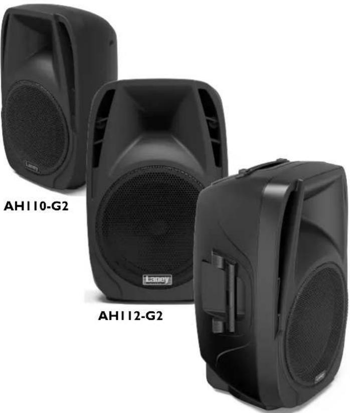
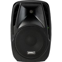
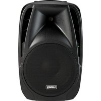
The Laney Audiohub Venue range of enclosures is designed to deliver a high performance in a wide variety of demanding audio applications.
The Audiohub Venue range is ideally suited for use in classrooms, business seminars, presentations, worship meets, parties, bars, BBQ's and a variety of different styles of musical performances.
Housing a flexible on-board mixer which includes a Bluetooth® equipped media player, each Audiohub Venue gives you a compact yet flexible solution to your audio sound reinforcement requirements.
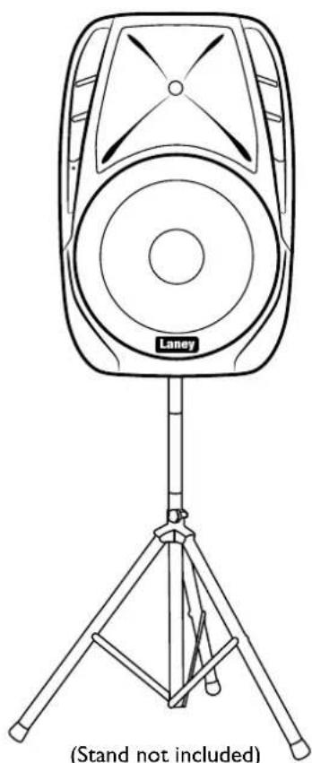
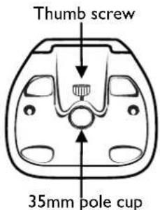
These lightweight, portable, full range moulded enclosures, can be either floor standing, mounted on a pole or tripod stand (via the 35mm pole socket), or used on stage as a wedge monitor.
This manual contains important information regarding correct and safe operation of your active system. Please read it thoroughly in order to get the best performance and reliability from your new Laney product.

natural_image
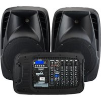
Three black audio speakers labeled AH110-G2 and AH112-G2, no additional text or symbols visible on the devices themselves.AH115-G2
REAR PANEL CONTROLS
1/2. CHI and CH2: Mono Input channels.
-
LEVEL: Use the Level control to set the channel volume.
-
LINE INPUT: An unbalanced input - for higher output line level devices eg. - keyboard, processor, drum machine.
5/5a. MIC/LINE INPUT: Use the push button (5a) to switch the XLR Skt between: MIC: a balanced input for low level, low impedance devices eg.-mic (200-600 Ohms) or electro-acoustic guitar. LINE (via XLR Input): A balanced input for higher output line level devices eg.-keyboard/drum machine.
-
CH3 LEVEL: Use this control to adjust the level of the onboard USB/SD player or an external (line level) signal feed connected to the AUX IN.
-
AUX IN: This gives you the option to connect an additional line level device. Control the Level with CH3 Level control. Please use a stereo cable.
-
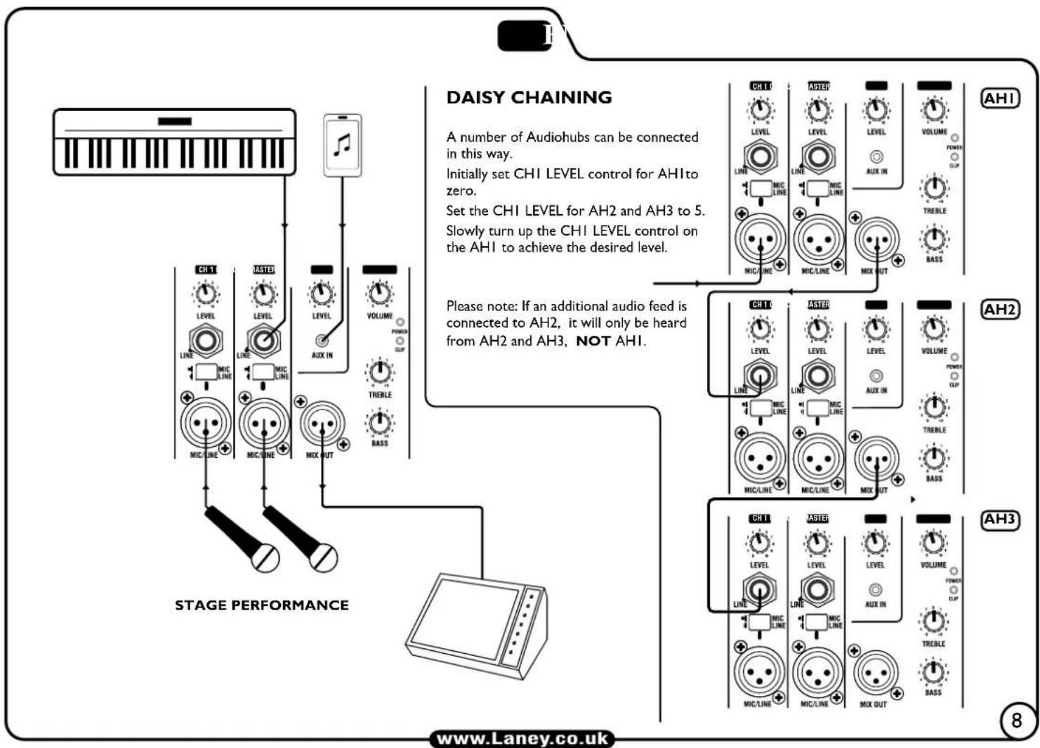
MIX OUT: A BALANCED signal feed that can be used to connect to a second Audiohub cab (daisy chained - see page 8), active wedge monitor, house PA or mixing console for example.
-
POWER LED: This will illuminate when the unit is powered up. There is also a second power LED on the front of the cab.
-
CLIP LED: Illuminates just before the amplifier begins to clip. Adjust the level controls and signal level from your source so this illuminates only briefly on peaks in the music.
II. MASTER VOLUME: Controls the overall level of your Audiohub.
-
ACTIVE BASS and TREBLE: These controls allow you to boost or cut the low/high frequency response of the Audiohub amplifier.
-
HEAT SINK: Cooling fins for the amplifier. Do not obstruct.
-
INFORMATION: Area relating to the amplifier: Serial Number, operational information, power rating, etc.
-
VOLTAGE SELECT SWITCH: Although every effort has been made to select the correct voltage for the region of use, please check before powering up for the first time. Damage could occur if the voltage is incorrectly set. See page 9 for more information.
-
MAINS SWITCH: Turns the system on and off. Ensure the Level/Volume controls are at minimum when switching on and off.
-
MAINS INLET SOCKET AND FUSE: IEC input for connection of an appropriate mains lead. Only replace the fuse with the type indicated for your mains voltage. See page 9 for more information.
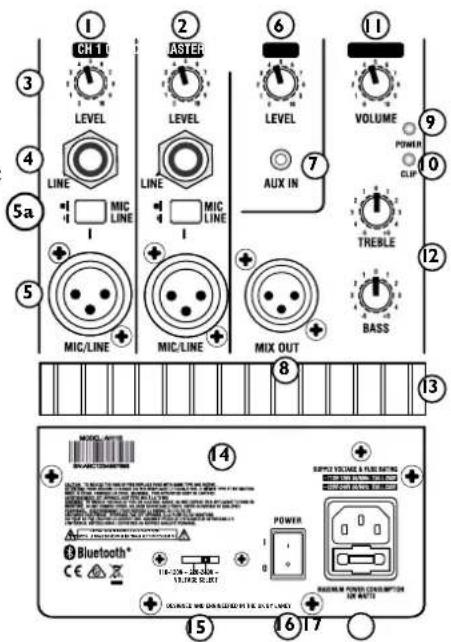
(AH115-G2 Panel shown)
MEDIA PLAYER CONTROLS

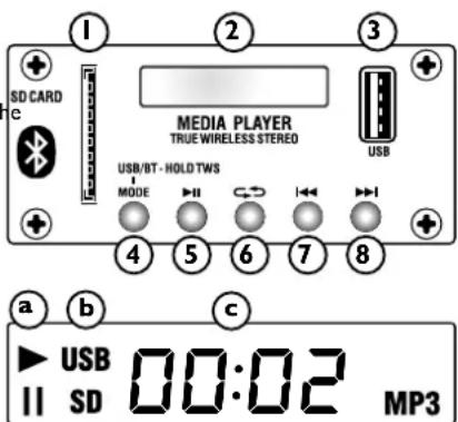
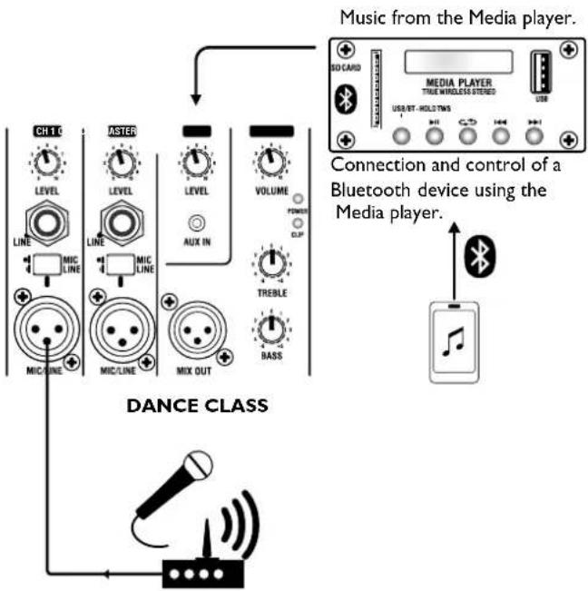
Use the onboard player for playing MP3 encoded audio tracks from SD card/USB or Bluetooth® device.
I. SD CARD SLOT: Insert your standard SD card here.
(Automatically detected on insertion, or if removed and reinserted uses smart technology to resume play from the previous point).
- DISPLAY SCREEN: Display track information.
a. Play or Pause indicator.
b. What device is being used: USB or SD Card.
c. Time into track.
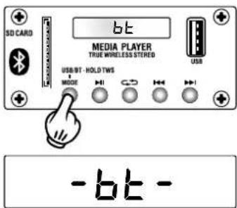
d. "bt" is displayed when connecting to a Bluetooth Device.
- MEMORY STICK SLOT: Connect your USB thumb drive here. If removed and reinserted, the system uses smart technology to resume play from the previous point.
NOTE. The USB socket is for the playback of recorded tracks only, not for charging a USB device.
-
MODE: Select the input source - SD card USB, Bluetooth/TWS with two cabinets. See page 6 for more information.
-
PLAY/PAUSE: Use this control to play or pause your MP3 music/backing track.
-
LOOP: Use this to enable/disable the looped playback modes. When using this button with an SD card or USB thumb drive, there are 3 options:
ALL - Plays all the tracks on the root of the device in date order, then the sub folders
ONE - Plays one track repeatedly (cycle to the required track to play using NEXT button (8).
FOD - Plays all track in the current active folder.
-
PREVIOUS: Press to skip to the preceding track. A prolonged press will reduce the volume of the MP3 player.
-
NEXT: Press to skip to the next track. A prolonged press will increase the volume of the MP3 player.
CONNECT TO BLUETOOTH DEVICE:
a. Toggle through the system modes and select Bluetooth (using MODE switch (4)).
b. On your Bluetooth capable device, make sure Bluetooth is enabled. Scan down the list of available devices - search for: 'Laney Audiohub' and select.
c. Your Audiohub enclosure is now connected to your Bluetooth device and controlled using the PLAY/PAUSE, PREVIOUS and NEXT BUTTONS.
d. Switching between a USB device and a Bluetooth device is possible, but the Bluetooth device will need to be re-selected by pressing the MODE button once.

TWS

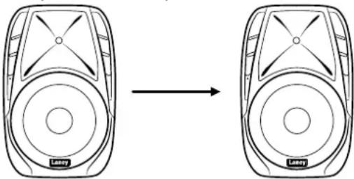
True Wireless Stereo is a feature that allows for the connection of two Audiohub cabinets to a Bluetooth capable device. The result is a true stereo system via Bluetooth with the first AudioHub providing the left and the second providing the right portion of the stereo image.
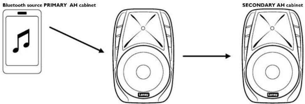
flowchart
graph LR
    A["Bluetooth source PRIMARY AH cabinet"] --> B["Second-tier Laney device"]
    B --> C["SECONDARY AH cabinet"]
SETTING UP THE CONNECTION
I. Connect the Primary Audiohub cabinet to a Bluetooth capable device as explained on the previous page.
2. Using the Mode switch, select the Bluetooth mode on the secondary cabinet, then hold the MODE switch for a further 5 - 10 seconds, then release. bE will appear on the display of both cabinets (flashing on and off) and indicates the TWS connection is in progress.
3. Once the connection has been established, the image (to the left) will appear on the display of both Primary and Secondary cabinet.
APPLICATIONS
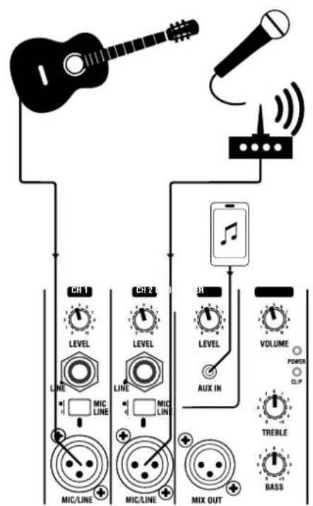
SOLO PERFORMANCE

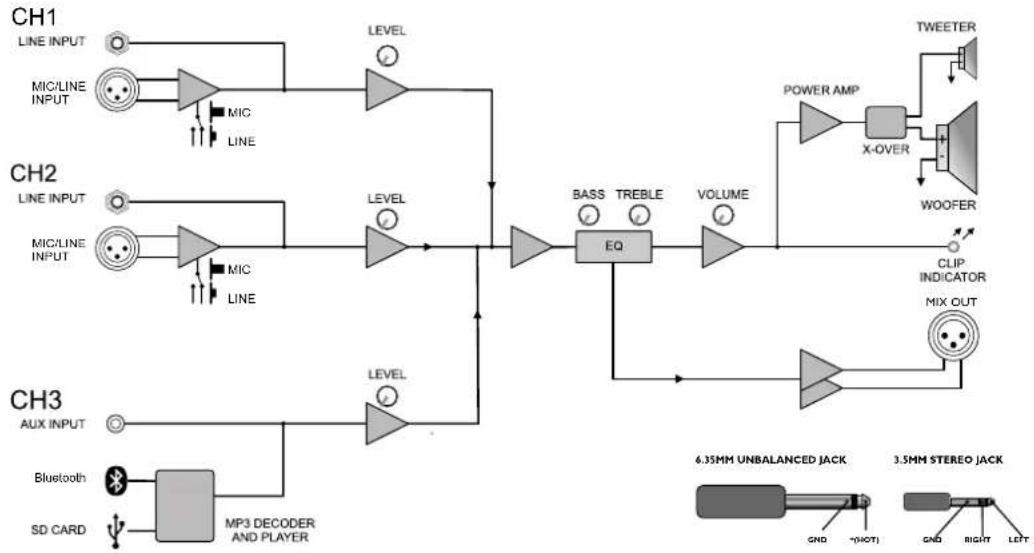
BLOCK DIAGRAM
EN
flowchart
graph TD
    subgraph CH1
        A["LINE INPUT"] --> B["MIC/LINE INPUT"]
        B --> C["MIC"]
        C --> D["LEVEL"]
        D --> E["EQ"]
        E --> F["BASS"]
        E --> G["TREBLE"]
        E --> H["VOLUME"]
        H --> I["X-OVER"]
        I --> J["WOOFER"]
        J --> K["TWEETER"]
    end

    subgraph CH2
        L["LINE INPUT"] --> M["MIC/LINE INPUT"]
        M --> N["MIC"]
        N --> O["LEVEL"]
        O --> E
        P["LINE INPUT"] --> Q["MIC"]
        Q --> R["LEVEL"]
        R --> E
        S["Line INPUT"] --> T["MIC"]
        T --> U["LEVEL"]
        U --> E
        V["AUX INPUT"] --> W["Bluetooth"]
        W --> X["MP3 DECODER AND PLAYER"]
        Y["SD CARD"] --> Z["MP3 DECODER AND PLAYER"]
    end

    subgraph CH3
        AA["6.35MM UNBALANCED JACK"] --> AB["GND"]
        AC["3.5MM STEREO JACK"] --> AD["GND"]
        AE["RIGHT"] --> AF["LEFT"]
    end

    style CH1 fill:#f9f,stroke:#333
    style CH2 fill:#f9f,stroke:#333
    style CH3 fill:#f9f,stroke:#333
I/O CONNECTOR
WIRING:
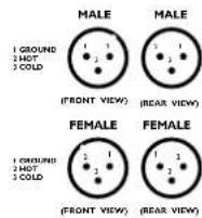
6.35MM UNBALANCED JACK
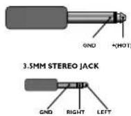
FUSE REPLACEMENT AND VOLTAGE SELECTION
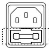
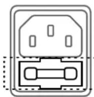
Switch off and disconnect the power cord before proceeding.
natural_image
Pure electrical outlet diagram without any text, numbers, or symbolsI.) Slide out the fuse holder tray.
2.) Only replace fuse with the same type and power rating as specified on the rear panel.
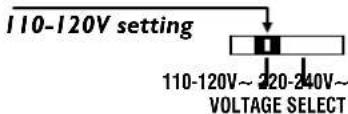
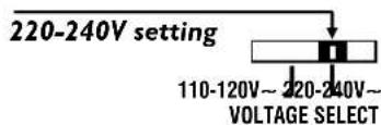
Using a suitable tool, slide the voltage selector switch to the required operating voltage.
POLE MOUNTING
natural_image
Line drawing of a Laney speaker mounted on a tripod stand (no text or symbols on the device itself)
All cabinets should be balanced and steady.
Don't over-extend poles/tripods; ensure at least 4 x the pole diameter is still inside the outer pole.
Make sure the legs have a good splay on tripods, but do not obstruct doorways or other access-ways.
If a pole mount is used, make sure that the thumb screw on the cabinet is tight.
Keep lights away from speakers; heat can cause fires / speaker damage.
Don't run cables across access-ways; if you have to, run them above doors or use approved cable covers.
Be aware of total power usage. Overloading a mains socket is potentially dangerous, and likely to cause a power out during use.
Keep lighting cables away from ALL sound cables including mains, use separate circuit for lights if possible.
Keep power and signal cables apart.
www.Laney.co.uk
SPECIFICATION: AHI10-G2

| Description | : Laney AUDIOHUB VENUE - Active Moulded Enclosure, 400W, 10"+1" CD - 3CH, Bluetooth/SD/USB |
| Amplifier | |
| Power Rating | : 400W |
| Amplifier Type | : Class A/B |
| Power Supply | : Linear Toroidal PSU - Switchable Voltage |
| Features | |
| Inputs | : 2x balanced XLR with mic/line switch, 2x 6.3mm single ended jack inputs, 1x 3.5mm stereo jack in, Media player with Bluetooth 5.0, USB and SD card |
| Outputs | : Balanced XLR mix out. |
| Controls | : CH1,2,3 Gain controls, Master 2 Band EQ, Master Volume |
| Speaker | |
| HF Driver | : 1" Compression Driver |
| LF Driver | : 10" Woofer |
| Coverage | : 90°H X 40°V |
| Enclosure | |
| Cabinet | : Robust polypropylene cabinet with top handle and monitor angle |
| Finish | : Black |
| Grille | : Powdercoated steel |
| Other | : 35mm Distance Pole |
| Unit dimensions (HWD) | : 49 x 31.5 x 26.5 CM19.3" x 12.4" x 10.4" |
| Unit weight | : 6.75Kg, 14.9 lbs |
| Carton dimensions (HWD) | : 55.5 x 37 x 30.5 CM21.9" x 14.6" x 12", 0.063 M3 |
| Packed weight | : 8.75Kg, 19.3 lbs |
In the interest of continued development, Laney reserves the right to amend product specification without prior notification.
SPECIFICATION: AHI12-G2

| Description | : Laney AUDIOHUB VENUE - Active Moulded Enclosure, 800W, 12"+1" CD - 3CH, Bluetooth/SD/USB |
| Amplifier | |
| Power Rating | : 800W |
| Amplifier Type | : Class A/B |
| Power Supply | : Linear Toroidal PSU - Switchable Voltage |
| Features | |
| Inputs | : 2x balanced XLR with mic/line switch, 2x 6.3mm single ended jack inputs, 1x 3.5mm stereo jack in, Media player with Bluetooth 5.0, USB and SD card |
| Outputs | : Balanced XLR mix out. |
| Controls | : CH1,2,3 Gain controls, Master 2 Band EQ, Master Volume |
| Speaker | |
| HF Driver | : 1" Compression Driver |
| LF Driver | : 12" Woofer |
| Coverage | : 90°H X 40°V |
| Enclosure | |
| Cabinet | : Robust polypropylene cabinet with three handles and monitor angle |
| Finish | : Black |
| Grille | : Powdercoated steel |
| Other | : 35mm Distance Pole |
| Unit dimensions (HWD) | : 58.5 x 37.5 x 31 CM23" x 14.8" x 12.2" |
| Unit weight | : 11.7Kg, 25.8 lbs |
| Carton dimensions (HWD) | : 66 x 43.5 x 36 CM26" x 17.1" x 14.2", 0.103 M3 |
| Packed weight | : 12.7Kg, 28 lbs |
In the interest of continued development, Laney reserves the right to amend product specification without prior notification.
SPECIFICATION: AHI15-G2

| Description | : Laney AUDIOHUB VENUE - Active Moulded Enclosure, 800W, 15"+1" CD - 3CH, Bluetooth/SD/USB |
| Amplifier | |
| Power Rating | : 800W |
| Amplifier Type | : Class A/B |
| Power Supply | : Linear Toroidal PSU - Switchable Voltage |
| Features | |
| Inputs | : 2x balanced XLR with mic/line switch, 2x 6.3mm single ended jack inputs, 1x 3.5mm stereo jack in, Media player with Bluetooth 5.0, USB and SD card |
| Outputs | : Balanced XLR mix out. |
| Controls | : CH1,2,3 Gain controls, Master 2 Band EQ, Master Volume |
| Speaker | |
| HF Driver | : 1" Compression Driver |
| LF Driver | : 12" Woofer |
| Coverage | : 90°H X 40°V |
| Enclosure | |
| Cabinet | : Robust polypropylene cabinet with three handles and monitor angle |
| Finish | : Black |
| Grille | : Powdercoated steel |
| Other | : 35mm Distance Pole |
| Unit dimensions (HWD) | : 71.5 x 46.5 x 38 CM28.1" x 18.3" x 15" |
| Unit weight | : 13.5Kg, 29.8 lbs |
| Carton dimensions (HWD) | : 74 x 48.5 x 40 CM29.1" x 19.1" x 15.7", 0.144 M3 |
| Packed weight | : 16.9Kg, 37.3 lbs |
In the interest of continued development, Laney reserves the right to amend product specification without prior notification.
Laney
USER MANUAL
TRANSLATION DOCUMENTS
WWW.LANEY.CO.UK
DESIGNED & ENGINEERED IN THE UK BY LANey
PANNEAU DE COMMANDE
FR
(AH115-G2 Panel shown)
FR
flowchart
graph LR
    A["Mobile Phone Icon"] --> B["Play button with musical note"]
    B --> C["Latency Device with X-axis label"]
    C --> D["Latency Device with X-axis label"]
RÉGLAGE DE LA CONNEXION
REPLACEMENT DU FUSIBLE
flowchart
graph LR
    A["Mobile Phone Icon"] --> B["Play button with musical note"]
    B --> C["Latency Device with X-axis label"]
    C --> D["Latency Device with X-axis label"]
AJUSTANDO LAS CONEXIONES
(AH115-G2 Panel shown)
REPRODUTOR DE MÍDIA

flowchart
graph LR
    A["Mobile Phone Icon"] --> B["Lasey Device"]
    B --> C["Lasey Device"]
FAZENDO AS CONEXÕES
(AH115-G2 Panel shown)
DE
MEDIA PLAYER
flowchart
graph LR
    A["Mobile Phone Icon"] --> B["Latency Display"]
    B --> C["Latency Display"]
Primary AH Cabinet Secondary AH Cabinet
(AH115-G2 Panel shown)
MEDIASPELER
Primary AH Cabinet Secondary AH Cabinet
DE VERBINDING TOT STAND BRENGEN
In order to take full advantage of your new product and enjoy long and trouble-free performance, please read this owner's manual carefully, and keep it in a safe place for future reference.
1) Unpacking: On unpacking your product please check carefully for any signs of damage that may have occurred whilst in transit from the Laney factory to your dealer. In the unlikely event that there has been damage, please re-pack your unit in its original carton and consult your dealer. We strongly advise you to keep your original transit carton, since in the unlikely event that your unit should develop a fault, you will be able to return it to you dealer for rectification securely packed.
2) Amplifier Connection: In order to avoid damage, it is advisable to establish and follow a pattern for turning on and off your system. With all system parts connected, turn on source equipment, tape decks, cd players, mixers, effects processors etc. BEFORE turning on your amplifier. Many products have large transient surges at turn on and off which can cause damage to your speakers. By turning on your bass amplifier LAST and making sure its level control is set to a minimum, any transients from other equipment should not reach your loud speakers. Wait till all system parts have stabilised, usually a couple of seconds. Similarly when turning off your system always turn down the level controls on your bass amplifier and then turn off its power before turning off other equipment.
3) Cables: Never use shielded or microphone cable for any speaker connections as this will not be substantial enough to handle the amplifier load and could cause damage to your complete system.
4) Servicing: The user should not attempt to service these products. Refer all servicing to qualified service personnel.
| Intended to alert the user to the presence of uninsulated 'Dangerous Voltage' within the products enclosure that may be sufficient to constitute a risk of electrical shock to persons.Ca symbole est utilise pur indiquer a l'utilisateur de ce produit de tension non-isoles dangereuse pouvant être d'intensite suffisante pour constituer un risque de choc électrique.Este simbolo tiene el proposito de alertar al usuario de la presencia de 'voltaje' peligroso' que no tiene aislamiento dentro de la caja del producto que puede tener una magnitud suficiente como para constituir riesgo de corrientazo.Dieses Symbol soll den Anwender vor unsolierten gefährlichen Spannungen innerhalb des Gehauses warnen, die von Ausrichender Starke sind, um einen elektrischen Schlag verursachten zu können. | |
| Intended to alert the user of the presence of important operating and maintenance (Servicing) instructions in the literature accompanying the product.Dieses Symbol soll den Anwender vor unsolierten gefährlichen Spannungen innerhalb des Gehauses warnen, die von Ausrichender Starke sind, um einen elektrischen Schlag verursachten zu können.Este simbolo tiene el proposito de la alertar al usuario de la presencia de instrucciones importantes sobre la operacion y mantenimiento en la literatura que viene conel producto.Dieses Symbol soll den Benutzer auf wichtige Instruktionen in der Bedienungsanleitung aufmerksam machen, die Handhabung und Wartung des Produkts betreffen. | |
| CAUTION:ATTENTION:PRECAUCION:VORSICHT: | Risk of electrical shock - DO NOT OPEN.To reduce the risk of electrical shock, do not remove the cover. No user serviceable parts inside. Refer servicing to qualified personnel.Riaques de choc électrique - NE PAS OUVIRIAfin de reduire le risque de choc électrique, ne pas erliever le couvercle. Il ne se trouve a l'interieur aucune pièce pouvant être reparse par l'utilisateur. Confler l'entretien a un personnel qualifie.Riesgo de corrientazo - no abraPara dominuir al risque de corrientazo, no abra la cubierta. No hay piezas adentro que el pueda reparar. Deje todo mantenimiento a los tecnicos calificado.Risiko - Elektrischer Schlag! Nicht offen!Lim das Risiko eines elektrischen Schilages zu vermeiden, nicht die Abdeckung entfernen. Es befinden sich keine Teile darin, die vom Anwender repariert werden Konnten. Reparaituren nur von qualifiziertem Fachpersoral durchführen lassen. |
| WARNING:ADVERTISSEMENT:ADVERTENCIA:ACHTUNG: | To prevent electrical shock or fire hazard, do not expose this appliance to rain or moisture. Before using this appliance please read the operating instructions for further warnings.Afin de prevenir les risques de recharge électrique ou de feu, n'exposes pas cet appareil a la pluie ou a l'humidite. Avant d'utiliser cet appareil, lesze les advertisements supplanteres situes dans le guide.Para evitar corrientazos o peligro de incendio, no deja expuesto a la livra o humedad este aparato Antes de usar este aparato, lea mas advertistas en la guía de operacion.Lim einen elektrischen Schalg oder Feuurgefahr zu vermeiden, sollte dieses Gerat nicht dem Regen oder Feuchtigkeit ausgesetzt werden.Vor Industriebnahme unbedingt die Bedienungsanleitung lessen. |
FCC COMPLIANCY STATEMENT

This device complies with Part 15 of the FCC rules.
Operation is subject to the following two conditions:
1) This device may not cause harmful interference
2) This device must accept any interference received, that may cause undesired operation.
Warning: Changes or modification to the equipment not approved by Laney can void the user's authority to use the equipment. Note: This equipment has been tested and found to comply with the limits for Class 8 digital device, pursuant to Part I5 of the FCC Rules. These limits are designed to provide reasonable protection against harmful interference in a residential installation. This equipment generates, uses and can radiate radio frequency energy and if not installed and used in accordance with the instructions, may cause harmful interference to radio communications. However, there is no guarantee that interference will not occur in a particular installation. If this equipment does cause harmful interference to radio or television reception, which can be determined by turning the equipment off and on, the user is encouraged to try and correct the interference by one or more of the following measures.
Reorient or relocate the receiving antenna.
Increase the separation between the equipment and receiver
Connect the equipment into an outlet on a circuit different from that to which the receiver is connected.
Consult the dealer or an experienced radio/TV technician for help

This product conforms to the requirements of the following European Regulations, Directives & Rules:
CE Mark (93/68/EEC), Low Voltage 2014/35/EU, EMC (2014/30/EU), RoHS (2011/65/EU), RED (2014/30/EU), ErP 2009/125/EU
In order to reduce environmental damage, at the end of its useful life, this product must not be disposed of along with normal household waste to landfill sites. It must be taken to an approved recycling centre according to the recommendations of the WEEE (Waste Electrical and Electronic Equipment) directive applicable in your country.

SIMPLIFIED EU DECLARATION OF CONFORMITY
Hereby, Laney Electronics Ltd. declares that the radio equipment is in compliance with Directives 2014/53/EU, 2011/65/EU,
2009/125/EU
Full text of the EU declaration of conformity is available at the following internet address:
support.laney.co.uk/approvals

The Bluetooth® word mark and logos are registered trademarks owned by the Bluetooth SIG, inc. and any use of such marks by Headstock Distribution Ltd is under license. Other trademarks and trade names are those of their respective owners. Laney is a registered trademark of Headstock Distribution Ltd.
INCORPORATED RADIO EQUIPMENT DEVICE TECHNICAL SPECIFICATION:
Frequency Range:
Transmit Power:
Receiver Sensitivity:
Operating Protocol: Bluetooth Class 2
IMPORTANT SAFETY INSTRUCTIONS
WARNING: When using electrical products, basic cautions should always be followed, including the following.
-
Read these instructions.
-
Keep these instructions sale.
-
Heed all warnings.
-
Follow all instructions.
-
Do not use this apparatus near water.
-
Clean only with a dry cloth
-
Do not block any of the ventilation openings, install in accordance with manufacturer's instructions.
-
Do not break any of the ventilation opening, install in laser devices with manufacturer's instructions.
- Do not install near any heat sources such as radiators, heat registers, stoves or other apparatus (including amplifiers) that produce heat.
- An apparatus with Class I construction shall be connected to a mains socket outlet with a protective connection. Do not defeat the safety
purpose of the polarized or grounding-type plug. A polarized plug has two blades with one wider than the other. A grounding type plug has two blades and a third grounding prong. The wide blade or third prong is provided for your safety. If the provided plug does not fit into your outlet, consult an electrician for replacement of the obsolete outlet.
-
Protect the power cord from being walked on or pinched, particularly at plugs, convenience receptacles, and the point they exit from the apparatus.
-
Only use attachments/accessories provided by the manufacturer.
-
Use only with a cart, stand, tripod, bracket, or table specified by the manufacturer, or sold with the apparatus. When a cart is used, use caution when moving the cars'apparatus combination to avoid injury from tip-over.
-
The mains plug or appliance coupler is used as the disconnect device and shall remain readily operable. The user should allow easy access to any mains plug, mains coupler and mains switch used in conjunction with this unit thus making it readily operable. Unplug this apparatus during lightning storms or when unused for long periods of time.
-
Refer all servicing to qualified service personnel. Servicing is required when the apparatus has been damaged in any way, such as when power supply cord or plug is damaged, liquid has been spilled or objects have fallen into the apparatus, the apparatus has been exposed to rain or moisture, does not operate normally, or has been dropped.
-
Never break off the ground pin. Connect only to a power supply of the type marked on the unit adjacent to the power supply cord.
-
If this product is to be mounted in an equipment rack, rear support should be provided.
-
Note for UK only: If the colours of the wires in the mains lead of this unit do not correspond with the terminals in your plug, proceed as follows:
a) The wire that is coloured green and yellow must be connected to the terminal that is marked by the letter E. the earth symbol, coloured green or
coloured green and yellow.
b) The wire that is coloured blue must be connected to the terminal that is marked with the letter N or the colour black.
The wire that is released brown must be connected to the terminal that is marked with the letter 1 or the colour red.
-
This electrical apparatus should not be exposed to dripping or splashing and care should be taken not to place objects containing liquids, such as vases, upon the apparatus.
-
Exposure to extremely high noise levels may cause a permanent hearing loss. Individuals vary considerably in susceptibility to noise-induced hearing loss, but nearly everyone will lose some hearing if exposed to sufficiently intense noise for a sufficient time.
The U.S. Government's Occupational Safety and Health Administration (OSHA) has specified the following permissible noise level exposures: According to OSHA, any exposure in excess of the above permissible limits could result in some hearing loss. Earplugs or protectors to the ear canals or over the ears must be worn when operating this amplification system in order to prevent a permanent hearing loss, if exposure is in excess of the limits as set forth above. To ensure against potentially dangerous exposure to high sound pressure levels, it is recommended that all persons exposed to equipment capable of producing high sound pressure levels such as this amplification system be protected by hearing protectors while this unit is in operation.
- Symbols & nomenclature used on the product and in the product manuals, intended to alert the operator to areas where extra caution may be necessary, are as follows:

Intended to alert the user to the presence of high 'Dangerous Voltage' within the products enclosure that may be sufficient to constitute a risk of electrical shock to persons.
Intended to alert the user of the presence of important operating and maintenance (Servicing) instructions in the literature accompanying the product.
Risk of electrical shock - DO NOT OPEN. To reduce the risk of electrical shock, do not remove the cover. No user serviceable parts inside. Refer servicing to qualified personnel.
To prevent electrical shock or fire hazard, do not expose this appliance to rain or moisture. Before using use read the operating instructions.
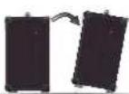
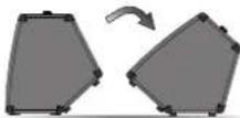
If your appliance features a tilting mechanism or a kickback style cabinet, please use this design feature with caution. Due to the ease with which the amplifier can be moved between straight and tilted back positions, only use the amplifier on a level, stable surface. DO NOT operate the amplifier on a desk, table, shelf or otherwise unsuitable non-stable platform.

The following described information is to the above reference exercise using the information obtained in accordance with the

PLEASE COMPLETE FOR FUTURE REFERENCE
LANEYAMPLIFICATION
LANEYAMPLIFICATION
LANEYAMPS
LANEYTV
DESIGNED & ENGINEERED IN THE UK BY LANEY
WWW.LANEY.CO.UK
- INTRODUCTION
- REAR PANEL CONTROLS
- MEDIA PLAYER CONTROLS
- CONNECT TO BLUETOOTH DEVICE:
- TWS
- SETTING UP THE CONNECTION
- POLE MOUNTING
- SPECIFICATION: AHI10-G2
- SPECIFICATION: AHI12-G2
- SPECIFICATION: AHI15-G2
- Laney
- TRANSLATION DOCUMENTS
- PANNEAU DE COMMANDE
- FR
- RÉGLAGE DE LA CONNEXION
- REPLACEMENT DU FUSIBLE
- AJUSTANDO LAS CONEXIONES
- REPRODUTOR DE MÍDIA
- FAZENDO AS CONEXÕES
- DE
- MEDIA PLAYER
- MEDIASPELER
- DE VERBINDING TOT STAND BRENGEN
- FCC COMPLIANCY STATEMENT
- IMPORTANT SAFETY INSTRUCTIONS
Brand : Laney
Model : AH115-G2
Category : Loudspeaker