1923 - Grill plate Blackstone - Free user manual and instructions
Find the device manual for free 1923 Blackstone in PDF.

User questions about 1923 Blackstone
0 question about this device. Answer the ones you know or ask your own.
Ask a new question about this device
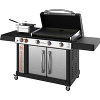
Download the instructions for your Grill plate in PDF format for free! Find your manual 1923 - Blackstone and take your electronic device back in hand. On this page are published all the documents necessary for the use of your device. 1923 by Blackstone.
USER MANUAL 1923 Blackstone
text_image
BLACKSTONE BLACKSTONEPlease reference blackstoneproducts.com/support for the latest version of this manual, and to follow along with assembly videos.
WARNING
INSTALLER/ASSEMBLER:
Leave these instructions with consumer.
CONSUMER: Retain this manual for future reference.
WARNING
This instruction manual contains important information necessary for the proper assembly and safe use of the appliance.
WARNING
Read all warnings and instructions before assembling the appliance.
Follow all warnings and instructions while using the appliance.
WARNING
Accessible parts may be very hot. Keep children and pets away from appliance at all times.
This appliance is not intended for use by children.
Close supervision is necessary when any appliance is used by or near children.
WARNING
This appliance is not intended for and should never be used as a heater.
Do not use for purposes other than intended.
Do not modify this appliance.
!DANGER
Never place any items within 3 in (8 cm) of the cooking surface while in use. This area can become very hot and potentially damage any accessory objects placed too close.
!DANGER
Do not store or use gaso- line or other flammable liquids or vapors in the vicinity of this or any other appliance.
Do not store a spare LPG cylinder under or near this appliance.
If these instructions are not followed exactly, a fire causing death or serious injury may occur.
!DANGER
IF YOU SMELL GAS:
- Shut off gas to appliance.
- Extinguish any open flame.
- Open lid.
- If odor continues, keep away from appliance and immediately call your gas supplier or your fire department.
Failure to follow these instructions could result in fire or explosion which could cause property damage, personal injury or death.
!DANGER
ONLY USE IN WELL- VENTILATED AREAS.
CARBON-MONOXIDE HAZARD - USING THIS APPLIANCE IN AN ENCLOSED SPACE MAY CAUSE DEATH.
!DANGER
- This appliance is for outdoor use only, and is not to be used in a building, garage, or any other enclosed area.
- DO NOT USE THIS APPLIANCE INSIDE OR ON RECREATIONAL VEHICLES, CARAVANS, TENTS, MARINE CRAFT, BOATS, CARS, MOBILE HOMES OR SIMILAR LOCATIONS.
- This appliance is not be used on or under any apartment or condominium balcony or deck.
!DANGER
If a fire should occur, keep away from the appliance and immediately call your fire department. DO NOT attempt to extinguish an oil or a grease fire with water.
⚠️DANGER
Never fill the LPG cylinder beyond 80% full.
WARNING
Keep the LPG container valves closed at all times unless the LPG system is in use or the container is being refilled.
IMPORTANT SAFEGUARDS
When using electrical appliances, basic safety precautions should always be followed including the following:
- Read all instructions.
- Do not touch hot surfaces. Use handles or knobs.
- To protect against electrical shock do not immerse cord, plugs, or appliance in water or other liquid.
- Close supervision is necessary when any appliance is used by or near children.
- Unplug from outlet when not in use and before cleaning. Allow to cool before putting on or taking off parts.
- Do not operate any appliance with a damaged cord or plug or after the appliance malfunctions or has been damaged in any manner. Return appliance to the nearest authorized service facility for examination, repair, or adjustment.
- The use of accessory attachments not recommended by the appliance manufacturer may cause injuries.
-
For Household use only.
-
Do not let cord hang over edge of table or counter, or touch hot surfaces.
- Do not place on or near a hot gas or electric burner, or in a heated oven.
- Extreme caution must be used when moving an appliance containing hot oil or other hot liquids.
- To disconnect, turn any control to "off", then remove plug from wall outlet.
- Do not use appliance for other than intended use.
- Fuel, such as charcoal briquettes, is not to be used with appliance.
- Use only on properly grounded outlet.
- CAUTION: Risk of Electric Shock. Keep extension cord connection dry and off the ground.
- For Outdoor use only, do not expose to rain.
- Be sure that handles are assembled and fastened properly.
SAVE THESE INSTRUCTIONS
For extension cords:
a. A short power-supply cord is provided to reduce the risk resulting from becoming entangled in or tripping over a longer cord.
b. Longer power-supply cords or extension cords are available and may be used if care is exercised in their use.
c. If a longer power-supply cord or extension cord is used:
- The marked electrical rating of the cord set or extension cord should be at least as great as the electrical rating of the appliance;
- The cord should be arranged so that it will not drape over the countertop or tabletop where it can be pulled on by children or tripped over unintentionally; and
- The cord set or extension cord should be a grounding-type 3-wire cord.
d. Outdoor extension cords should be used with outdoor use products and are surface marked with the suffix letter "W" and with a tag stating "Suitable for use with outdoor appliances."
e. The connection to an Extension cord should be kept dry and off the ground.
f. Store products indoors when not in use - out of the reach of children.
g. Do not clean this product with a water spray or the like.
This appliance is safety certified for use in the United States and/or Canada only. Do not modify for use in any other location. Modification will result in a safety hazard and void warranty.
WARNING
This product can expose you to chemicals including Di(2-Ethylhexyl) Phthalate (DEHP), which is known to the State of California to cause cancer and birth defects or other reproductive harm, and Diisononyl Phthalate(DINP), which is known to the State of California to cause cancer. For more information, go to www.P65Warnings.ca.gov.
WARNING
Fuels used in liquefied propane gas appliances, and the products of combustion of such fuels, can expose you to chemicals including benzene, which is known to the State of California to cause cancer and cause birth defects or other reproductive harm. For more information go to www.P65Warnings.ca.gov.
INSTALLATION SAFETY
Appliance installation must conform with local codes, or in the absence of local codes, with either the National Fuel Gas Code, ANSI Z223.1/ NFPA 54, Natural Gas and Propane Installation Code, CSA B149.1, or Propane Storage and Handling Code, B149.2, or the Standard for Recreational Vehicles, NFPA 1192, and CSA Z240 RV Series, Recreational Vehicle Code, as applicable.
TABLE OF CONTENTS
It is the consumer's responsibility to see that the unit is properly assembled, installed, and maintained. Failure to follow the instructions in this manual could result in bodily injury and/or property damage.
CONTENTS
- REGISTER YOUR PRODUCT .... 01
- FOR YOUR SAFETY 02
Section 01. Food Safety 02
Section 02. Gas Appliance Safety ....03
Section 03. Air Fryer Safety....04
- ASSEMBLY GUIDE ...... 05
- RECIPES FOR THE AIR FRYER ....21
- FUEL | 20 LB. (9 KG) PROPANE TANK....22
Section 01. LPG Cylinder Requirements ..... 22
Section 02. Connection & Removal....23
Section 03. Leak Test Instructions ...... 25
- CARE & MAINTENANCE....26
Section 01. General Care....26
Section 02. Cleaning the Burner Assembly 28
Section 03. Griddle Seasoning Instructions....30
Section 04. Cleaning Your Griddle Top ....32
Section 05. Cleaning Your Air Fryer .... 34
- IGNITION | AIR FRYER....35
- IGNITION | BATTERY POWERED....36
- TROUBLESHOOTING 37
Section 01. Battery Powered Ignition ....37
Section 02. Gas Flow....38
- RECIPES FOR THE GRIDDLE .... 40
- WARRANTY....43
⚠️DANGER
Indicates an imminently hazardous situation which, if not avoided, may result in death or serious injury.
WARNING
Indicates the possibility of serious bodily injury if the instructions are not followed.
CAUTION
Indicates a potentially hazardous situation which, if not avoided, may result in minor or moderate injury.
REGISTER YOUR PRODUCT
Registration allows our Customer Service Representatives to quickly provide assistance with your Blackstone product if needed.
The North Atlantic Imports LLC 1-Year Warranty covers replacement parts up to one year after the date of purchase. (Please reference the Warranty chapter for more information.) To enable this warranty, you will need to provide:
• Proof of Purchase/ Receipt/ Order Details
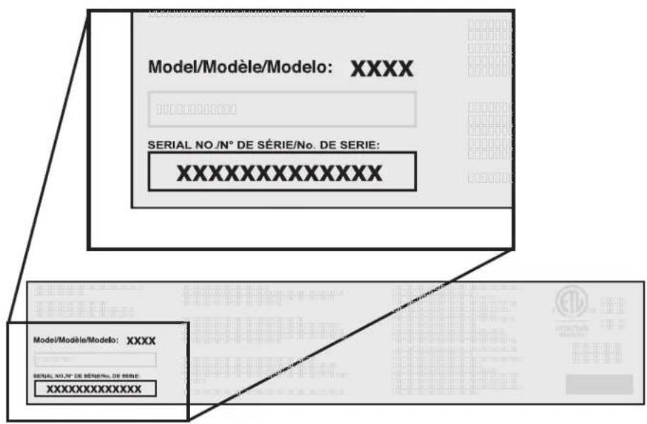
- Your Blackstone product's Serial Number
- Your Blackstone product's Model Number
Your Blackstone product's Serial and Model numbers can be found on your griddle's Origin Label. (The Origin Label is a large silver sticker found on the body of your appliance.)
text_image
Model/Modèle/Modelo: XXXX SERIAL NO./N° DE SÉRIE/No. DE SERIE: XXXXXXXXXXXXXX Model/Modèle/Modelo: XXXX SERIAL NO./N° DE SÉRIE/No. DE SERIE: XXXXXXXXXXXXXXModel Number ____
Serial Number
Date Purchased ____
OUR CUSTOMER
SERVICE STAFF IS
HERE TO HELP YOU!
Register your Blackstone product at
blackstoneproducts.com/register
and visit us online at
blackstoneproducts.com/support

We are pleased to help you with any questions concerning appliance use, replacement parts, or your warranty.
Customer Service Hours:

Monday - Friday
7:00 am - 5:00 pm (MST)
!DANGER
Never operate this appliance unattended.
WARNING
NEVER partially cook meat or poultry to finish cooking later. Cook food completely to destroy harmful bacteria.
WARNING
The use of alcohol, prescription or non-prescription drugs may impair the consumer's ability to properly assemble or safely operate the appliance.
CAUTION
For residential and house- hold use only. DO NOT use for commercial cooking.
CAUTION
Use long-handled cooking utensils and oven mitts to protect against burns and splatters.
CAUTION
- Do not place any empty cooking or frying vessels on the cooking surface while in operation.
- Use caution when placing anything in cooking vessel while the appliance is in operation.
FOR YOUR SAFETY
Before proceeding, make certain that you understand the FOR YOUR SAFETY section of this manual. Hazardous fire or explosion may result if instructions are ignored.
Section 01
FOOD SAFETY
Food safety is an important part of enjoying the outdoor cooking experience. To keep food safe from harmful bacteria, follow these four basic steps:
CLEAN: Wash hands, utensils, and surfaces with hot soapy water before and after handling raw meat and poultry.
SEPARATE: Separate raw meats and poultry from ready-to eat foods to avoid cross contamination. Use clean platter and utensils when removing cooked foods from appliance.
COOK: Cook meat and poultry thoroughly to kill bacteria. Use thermometer to ensure proper internal food temperatures.
CHILL: Refrigerate prepared foods and leftovers promptly.
For more information visit foodsafety.gov or Canadian Partnership for Consumer Food Safety Education online at befoodsafe.ca
HOW TO TELL IF MEAT IS COOKED THOROUGHLY
Meat and poultry cooked with this appliance often browns very fast on the outside.
Use a meat thermometer to be sure food has reached a safe internal temperature and cut into food to check for visual signs of doneness.
When reheating takeout foods or fully cooked meats like hot dogs, cook to 165^ F ( 74^ C), or until steaming hot.
MEAT COOKING TEMPERATURES
Poultry
165^ For 74^ C
Juices should run clear and flesh should not be pink.
Beef or Poultry Hamburger
160^ For 71^ C
Juices should not be pink and flesh should be brown in the middle.
Beef, Veal, & Lamb
Steaks/Chops
145^ For 63^ C
Beef, Veal, & Lamb Roasts
145^ For 63^ C
ALL cuts of 🍒 Pork
160^ For 71^ C
Juices should not be pink.
Section 02
GAS APPLIANCE SAFETY
If grease or other hot material drips from appliance onto valve, hose or regulator:
STEP 01 Turn off gas supply immediately.
STEP 02 Determine the cause and correct it.
STEP 03 Clean and inspect valve, hose and regulator before continuing.
STEP 04 Perform a leak test. (Please reference the Leak Test Instructions in the Fuel chapter.)
For problems with this appli- ance, please reference the Troubleshooting chapter.
WARNING
If the appliance is not in use, the gas must be turned off at the supply cylinder.
Storage of an appliance indoors is permissible only if the cylinder is disconnected and removed from the appliance.
The cylinder supply system must be arranged for vapor withdrawal.
The pressure regulator and hose assembly supplied with the appliance must be used.
Replacement pressure regulators and hose assemblies shall be those specified by the appliance manufacturer.
WARNING
Use this appliance, as purchased, only with gas and regulator/valve assembly supplied.
WARNING
DO NOT use this appliance under extended awnings. Failure to comply could result in a fire or personal injury.
!DANGER
When not in use, turn OFF appliance by rotating the appliance control knobs to the OFF position and closing the fuel valve.
If the information in the above statements is not followed exactly, serious injuries, fire, or death may occur.
!DANGER
When cooking with oil or grease, have a type BC or ABC fire extinguisher readily available.
!DANGER
DO NOT operate this appliance any closer than 36 in (1 m) from the sides and back of the appliance. Do not use this appliance under overhead combustible surfaces.
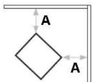

A = 36" (1 m)
CAUTION
Do not move the appliance when in use. Allow cooking vessel to cool to 115°F (45°C) before moving or storing.
!DANGER
This appliance is not for frying turkeys.
!DANGER
- Operating the air fryer can cause the griddle to become hot. Do not touch hot surfaces. Use protective gloves or mitts when opening drawers to prevent burns, as the drawer face may be hot.
- Do not place fryer drawers on griddle surface.
- Do not place fryer drawers on or near a hot gas or electric burner, or in a heated oven.
WARNING
DO NOT clean with alcohol or any other flammable substance.
!DANGER
- The power cord must be electrically grounded in accordance with local codes or, in the absence of local codes, with the National Electrical Code, ANSI/NFPA 70, or the Canadian Electrical Code, CSA C22.1.
- Keep the electrical supply cord and the fuel supply hose away from any heated surface(s).
- Use only a Ground Fault Interrupter (GFI) protected circuit.
- Never remove the grounding plug or use with an adapter of 2 prongs.
- Use only extension cords with a 3 prong grounding plug, rated for the power of the equipment, and approved for outdoor use with a W-A marking.
WARNING
The supply cord should be regularly examined for signs of damage, and the appliance is not to be used if the cord is damaged.
Section 03
AIR FRYER SAFETY
AIR FRYER
- Do not restrict the flow of the combustion air or the hot exhaust gasses.
- Blow out drawers before cooking to keep passageways clean.
- Remove items from bottom shelf of the unit before operating the air fryer.
- Allow to cool before putting on or taking off parts, cleaning or moving.
EXTENSION CORDS
Longer power-supply cords or extension cords are available and may be used if care is exercised in their use.
FOOD
- Do not cook food in the drawer without the basket in place.
- Do not overfill basket, air needs to flow around and between the pieces of food.
- Use a food thermometer to confirm food is cooked.
- If food begins to burn, turn off burners and close tank valve.
- Food in the baskets will become very hot, use gloves and/or tongs to handle food.
- Do not add liquids (water or sauces) to hot food in the drawer as it may flash to steam and cause burns.
- Use caution when removing drawers as hot food or hot liquids may spill.
ASSEMBLY GUIDE
EXPLODED VIEW
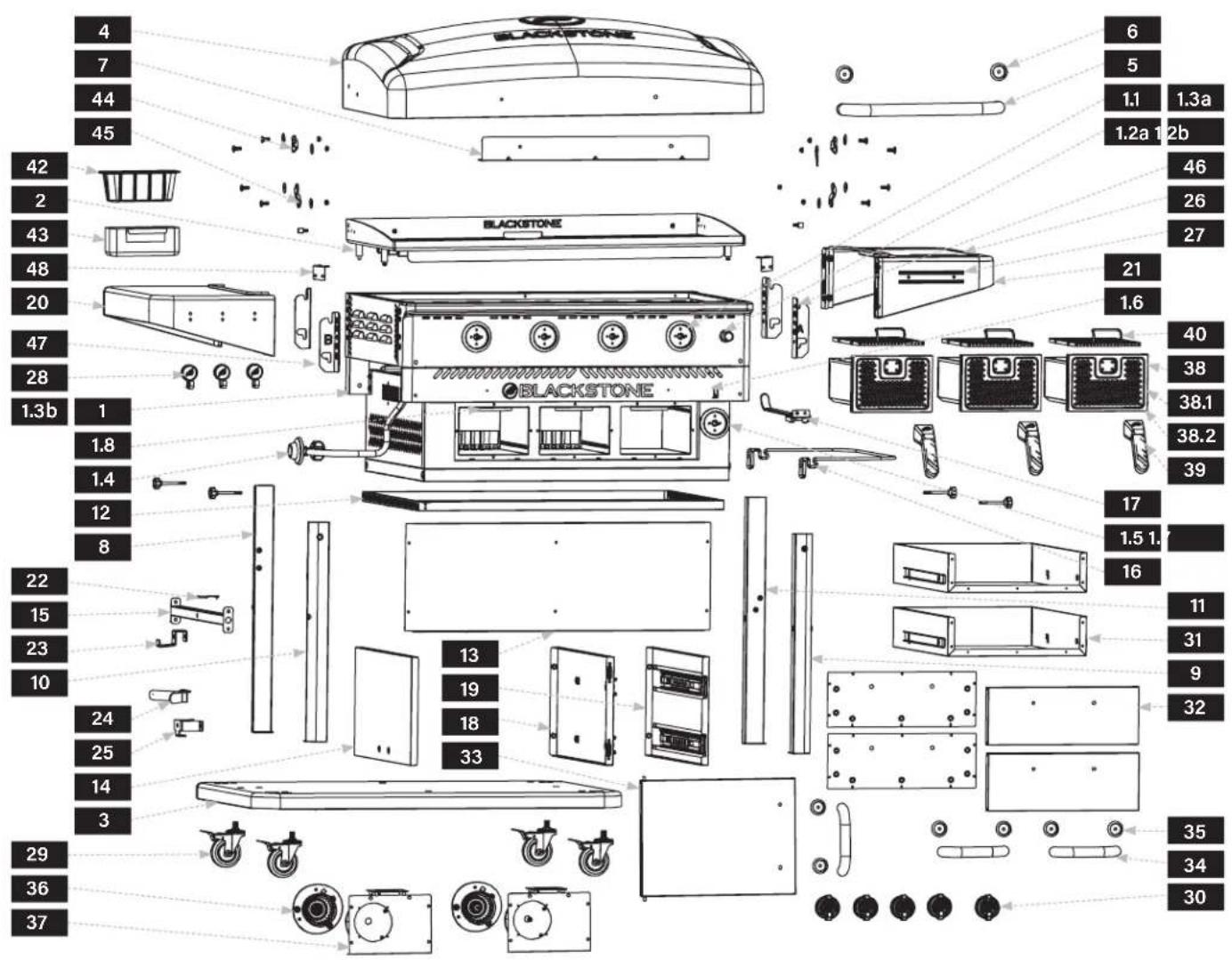
text_image
4 7 44 45 6 5 1.1 1.3a 1.2a 1.2b 42 2 43 48 20 47 28 1.3b 1 1.8 1.4 12 8 22 15 23 10 24 25 14 3 29 36 37 BLACKSTONE BLACKSTONE 13 19 18 33 17 1.5 1. 16 11 31 9 32 35 34 30| PARTS | QTY | |
| 1.1 | Control knob bezels | 4 |
| 1.2a | Electric ignitor | 1 |
| 1.2b | Electric ignitor wire (5pcs per set) with electrode | 1 |
| 1.3a | Griddle tubular burners | 4 |
| PARTS | QTY | |
| 1.3b | Gas rail & Valves | 1 |
| 1.4 | Regulator hose | 1 |
| 1.5 | Air fryer control knob bezel | 1 |
| 1.6 | Motor switch | 1 |
| 1.7 | Air fryer H burner | 1 |
| PARTS | QTY | |
| 1.8 | Motor assembly | 2 |
| 1.9 | Power cord | 1 |
| 38.1 | Air fryer drawer front panels | 3 |
| 38.2 | Silicone pads(4 pcs per pack) | 3 |
ILLUSTRATED PARTS LIST
1 Griddle body (1 piece)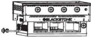 | 2 Griddle top (1 piece)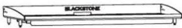 | 3 Bottom tray (1 piece) | |
4 Hood (1 piece)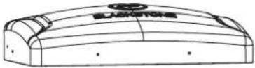 | 5 Hood handle (1 piece)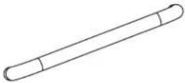 | 6 Hood handle bezels (2 pieces) | 7 Topper bracket (1 piece)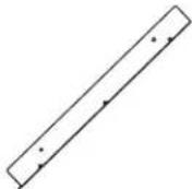 |
8 Left-rear leg (1 piece)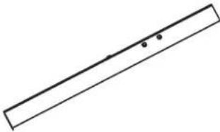 | 9 Right-rear leg (1 piece)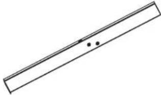 | 10 Left-front leg (1 piece)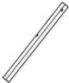 | 11 light-front leg (1 piece)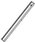 |
12 Top cart panel (1 piece) | 13 Back cart panel (1 piece)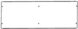 | 14 Left cart panel (1 piece)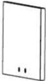 | 15 Crossbar assembly (1 piece)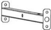 |
16 Garbage bag holder (1 piece)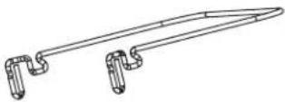 | 17 Paper towel holder (1 piece)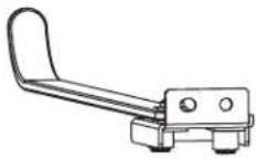 | 18 Middle cart panel (1 piece)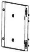 | 19 Right cart panel (1 piece)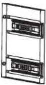 |
20 left side shelf (1 piece)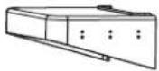 | 21 light side shelf (1 piece)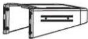 | 22 Hose retainer (1 piece)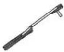 | 23 Upper propane tank hanger (1 piece)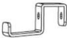 | 24 lower propane tank support (1 piece)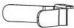 | 25 tropane tank bracket (1 piece) |
26 Cutting board (1 piece)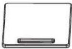 | 27 Magnetic strip (1 piece)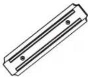 | 28 Shelf hooks (3 pieces)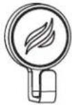 | 29 Lockable caster wheels (4 pieces)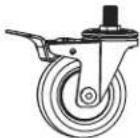 | 30 Control knobs (5 pieces) | 31 cart drawer assembly (2 pieces)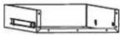 |
32 Cart drawer front panels (2 pieces)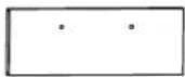 | 33 Cart door (1 piece)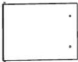 | 34 Cart door/ drawer handles (3 pieces) | 35 Cart door/ drawer handle bezels (6 pieces) | 36 Motors (2 pieces)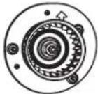 | 37 Motor shells and brackets (2 pieces)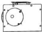 |
38 Air fryer drawer assembly (3 pieces)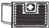 | 39 Air fryer drawer handles (3 pieces)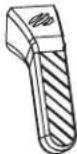 | 40 Air fryer drawer trivets (3 pieces)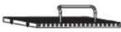 | 41 Lower cord bracket (1 piece)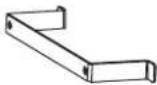 | 42 Aluminum grease cup liner (1 piece)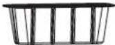 | 43 Grease cup (1 piece)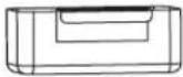 |
44 Hood hinge lever 1 (2 pieces)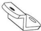 | 45 Hood hinge lever 2 (2 pieces)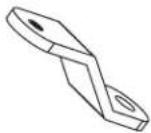 | 46 Shelf bracket “A” (2 pieces)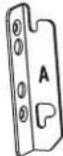 | 47 Shelf bracket “B” (2 pieces)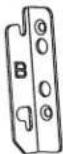 | 48 Briddle top holding brackets (2 pieces)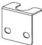 | |
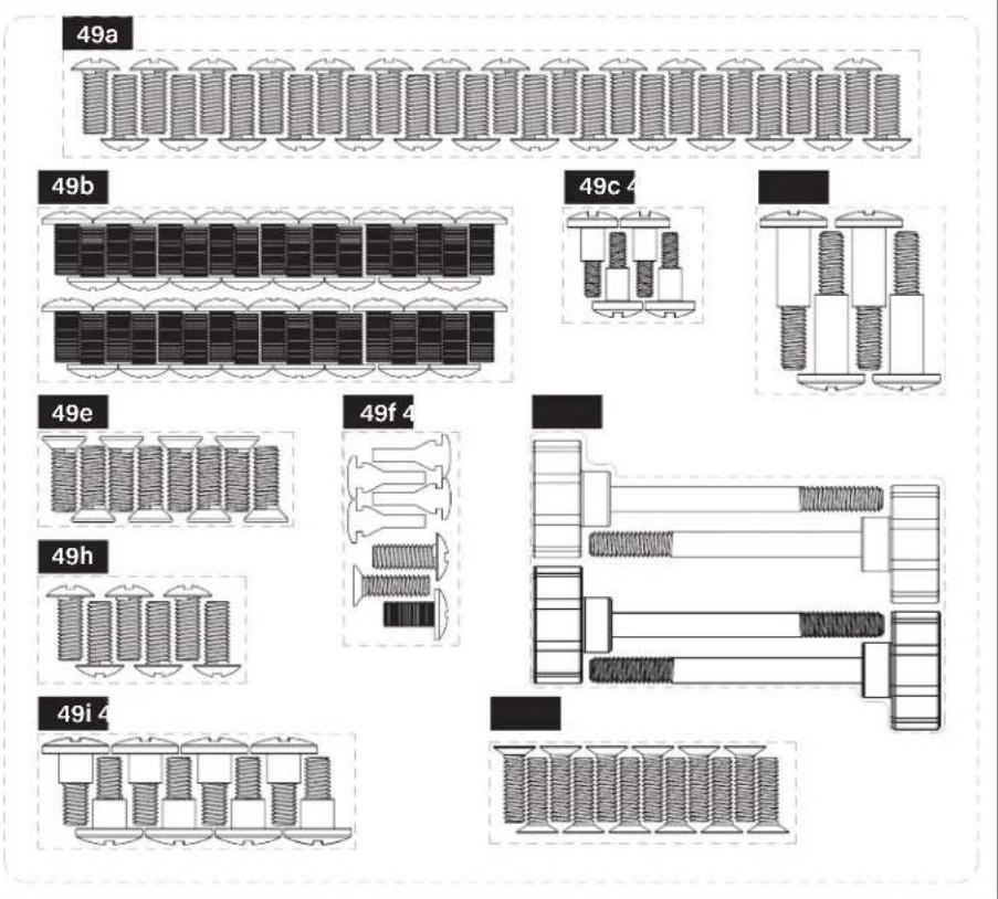
49 Hardware pack (1 piece)
a. M6x12 screws (28 pieces)
b. M5x10 screws (34 pieces)
c. M5 step bolts (4 pieces)
d. Long M6x35 step bolts (4 pieces)
e. M6x15 screws (8 pieces)
f. Spares
g. M6 thumbscrews (4 pieces)
h. M6x15 screws (6 pieces)
i. Short M6 step bolts (8 pieces)
j. M5x15 screws (12 pieces)
text_image
49a 49b 49c 4 49e 49f 4 49h 49i 4ELECTRIC REQUIREMENTS: 120V 60Hz 1.0A
natural_image
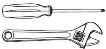
Line drawings of two wrenches: a standard screwdriver and an adjustable wrench (no text or symbols present)TOOLS NEEDED: Phillips head screwdriver & Adjustable wrench
natural_image
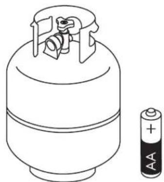
Line drawing of a cylindrical battery with a separate 2.5V battery (no text or symbols)NOT INCLUDED:
20 lb (9 kg) LPG tank & AA Battery
ASSEMBLY INSTRUCTIONS
Please read all instructions thoroughly before proceeding. Ensure that all plastic packing material and any transit protection is removed before assembling.
Find a large, clean area to assemble your unit. Please refer to the parts list and assembly diagrams as necessary.
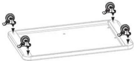
STEP 01 Turn the bottom tray upside down and screw on the four (4) lockable caster wheels. Be sure that the wheels are locked before attaching them.
natural_image
Technical line drawing of a rectangular frame with four circular components attached (no text or symbols)STEP 02 Use three (3) M6x12 screws (a.) to attach the left cart panel to the bottom tray.
text_image
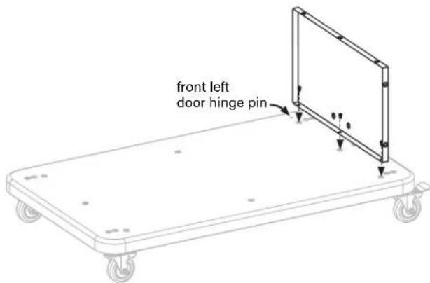
front left door hinge pinSTEP 03 Use five (5) M6x12 screws (a.) to attach the right cart panel and middle cart panel to the bottom tray. (Note: the magnets should face the front.)
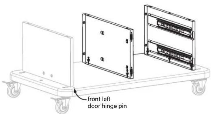
text_image
front left door hinge pinWARNING
The manufacturer has made every effort to eliminate any sharp edges. However, you should handle all components with care to avoid accidental injury.
Some parts may contain sharp edges, especially as noted in these instructions. Wear protective gloves if necessary.
CAUTION
Two people are recommended for the assembly of this product.
STEP 04 Use six (6) M5x10 screws (b.) to attach the back cart panel to the left cart panel, middle cart panel and right cart panel.
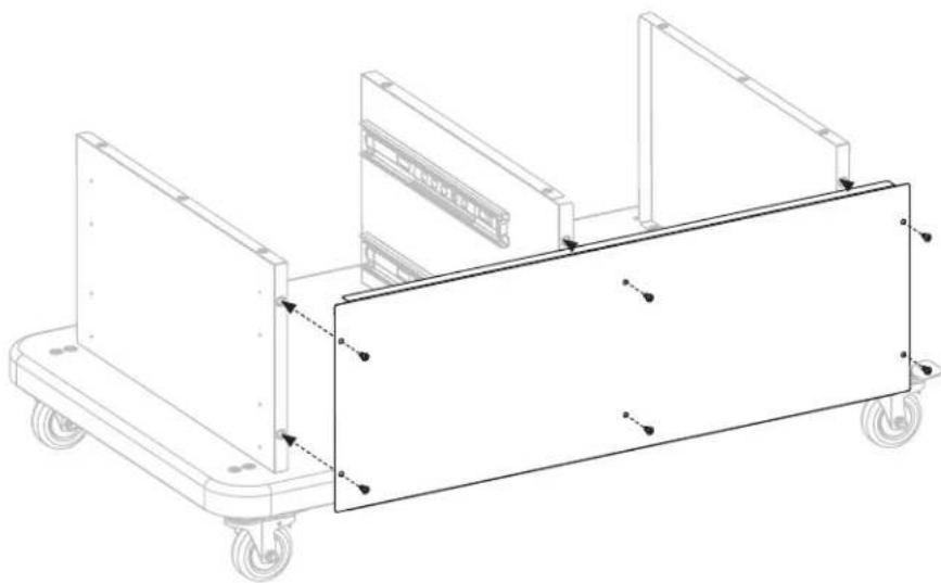
natural_image
Technical line drawing of a mechanical cart with wheels and structural supports (no text or symbols)STEP 05 Use eight (8) M5x10 screws (b.) to attach the top cart panel to the left cart panel, middle cart panel and right cart panel.
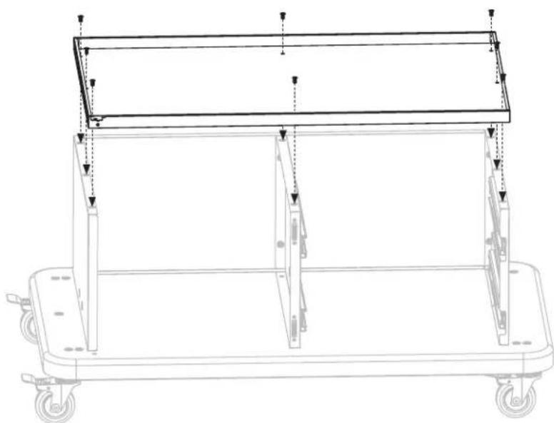
natural_image
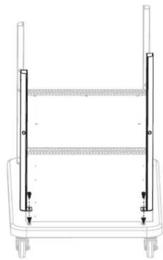
Technical line drawing of a mechanical cart with wheels and support legs (no text or symbols)STEP 06 Use four (4) M6x12 screws (a.) to attach the left-front leg and left-rear leg to the bottom tray. (Note: the front leg is shorter than the rear leg.)
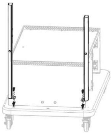
natural_image
Technical line drawing of a rectangular frame with vertical supports and mounting holes (no text or symbols)STEP 07 Use four (4) M6x12 screws (a.) to attach the right-front leg and right-rear leg to the bottom tray. (Note: the front leg is shorter than the rear leg.)
natural_image
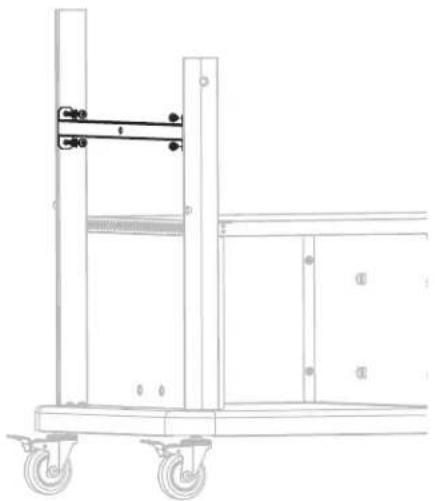
Technical line drawing of a mechanical frame with vertical supports and mounting holes (no text or symbols)STEP 08 Use four (4) M5x10 screws (b.) to attach the crossbar assembly to the left-front and left-rear legs.
natural_image
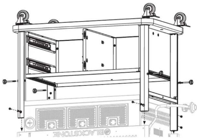
Technical line drawing of a mechanical cart with wheels and a handle (no text or symbols)STEP 09 With the help of another person, set the griddle body upside down. With the help of another person, slide the cart legs into the slots of the griddle body. Use six (6) M6x12 screws (a.) to attach the legs to the griddle body. Use four (4) thumbscrews (g.) to attach the legs to the airfryer body. (Do not fully tighten screws at this time.)
natural_image
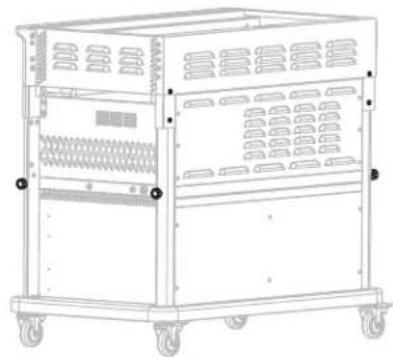
Technical line drawing of a server rack with mounting feet and internal compartments (no text or symbols)STEP 10 With the help of another person, set the griddle on its feet and tighten the screws.
natural_image
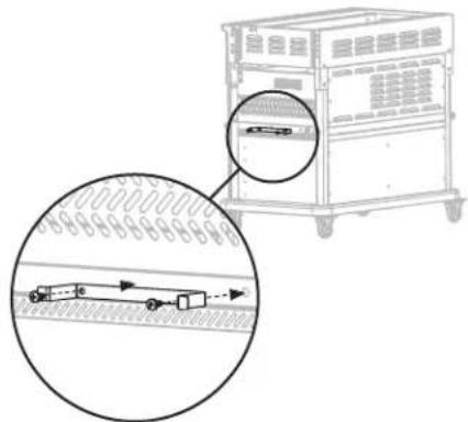
Line drawing of a multi-wheeled industrial machine with wheels and ventilation grilles (no text or symbols)STEP 11 Unscrew the two (2) M6x12 screws from the right side of the griddle, then use these screws to attach the power cord bracket to the right side of the griddle.
natural_image
Technical diagram showing a mechanical device with a magnified inset of its side view (no text or symbols present)STEP 12 Use two (2) M5x10 screws (b.) to attach the paper towel holder to the right-front leg.
natural_image
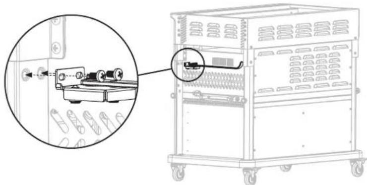
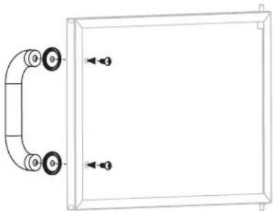
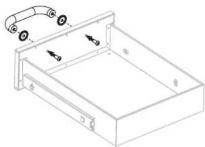
Technical line drawing of a mechanical device with a magnified inset showing internal components (no text or symbols)STEP 13 Use two (2) M6x12 screws (a.) to attach one (1) cart door/drawer handle and two (2) bezels to the cart door.
natural_image
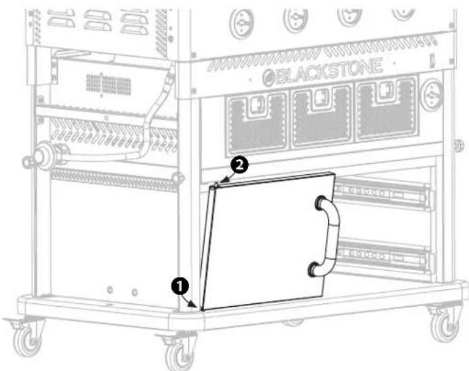
Simple line drawing of a rectangular panel with two wheels and an attached curved arm (no text or symbols)STEP 14 Attach the cart door assembly to the cart by first ① inserting the door into the lower door hinge pin, then ② pressing down and inserting the upper door hinge pin.
text_image
BLACKSTONE ① ②STEP 15 Use seven (7) M5x10 screws (b.) to attach the cart drawer front panel to the cart drawer body. Repeat this step with the other drawer.
natural_image
Pure diagram of a rectangular frame with vertical supports and arrows, no text or symbols presentSTEP 16 Use two (2) long M6x35 step bolts (d.) to attach one (1) cart door/drawer handle and two (2) bezels to the cart drawer front panel. Repeat this step with the other drawer.
natural_image
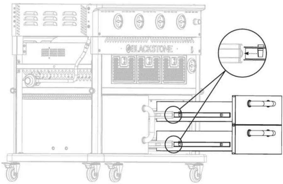
Technical line drawing of a rectangular device with internal components and a curved handle (no text or symbols)STEP 17 Pull out the four (4) cart sliding tracks from the middle and right cart panels. Insert the drawer sliding tracks into the cart tracks.
text_image
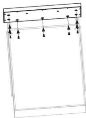
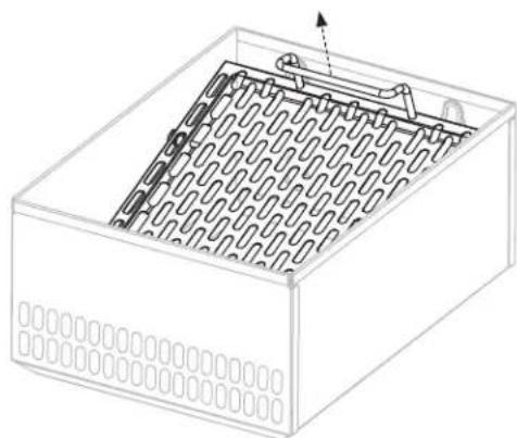
BLACKSTONE B B BSTEP 18 With the help of another person, lift the griddle top with hood assembly and place the griddle top on the main body by aligning the four (4) pins to the holes of the body. Make sure the front pins are fully seated in the holes, then push the griddle top back to lock the griddle in place.
text_image
BLACKSTONE BLACKSTONE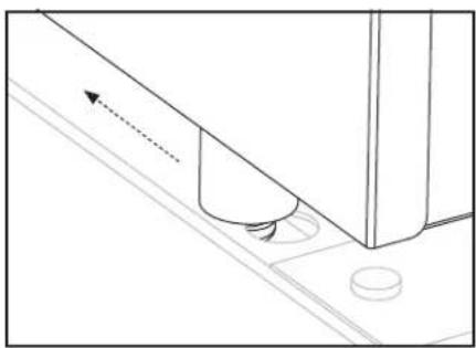
natural_image
Technical line drawing of a mechanical component with a curved arrow indicating direction (no text or symbols)Ensure that all four pins are seated in the holes, then push the griddle top back to lock the griddle in place.
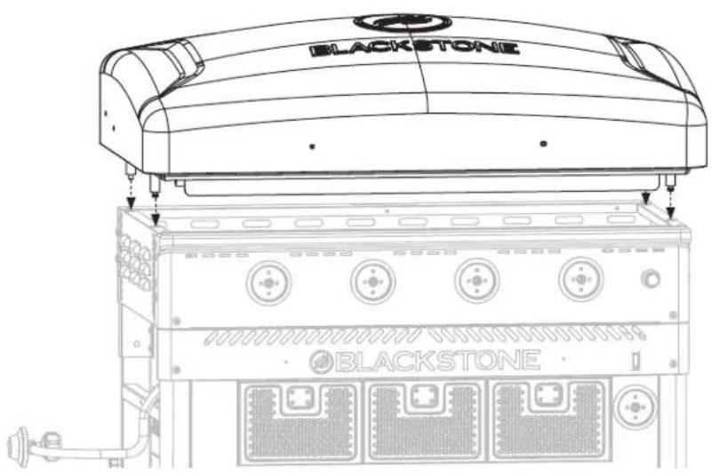
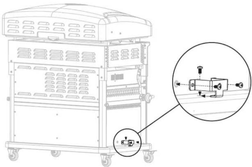
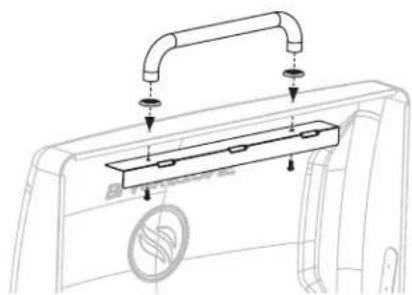
STEP 19 Use two (2) M6x12 screws (a.) to attach one (1) griddle top holding bracket to the left side of the griddle body. Repeat this step on the right side of the griddle.
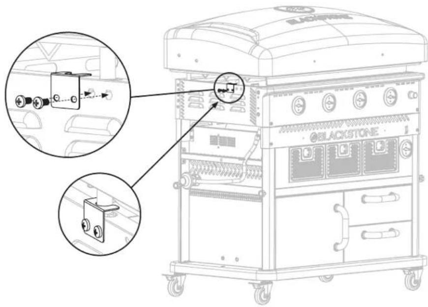
text_image
Technical diagram of a blackstone industrial machine with labeled components and close-up insets showing internal wiring connections.STEP 20 Use three (3) M6x15 screws (h.) to attach the propane tank bracket to the left cart panel.
natural_image
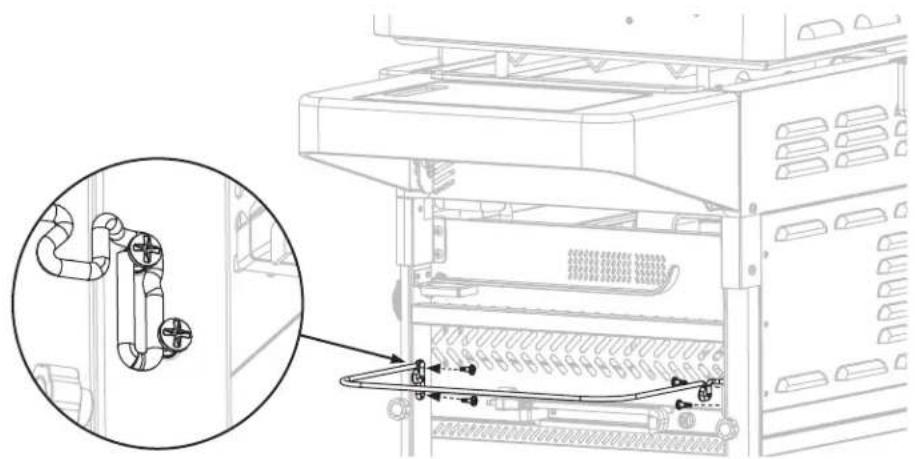
Technical line drawing of a mechanical device with an inset close-up showing internal components (no text or symbols)STEP 21 Use one (1) M6x15 screw (h.) to attach the propane tank hanger to the left leg assembly. Use one (1) M6x15 screw (h.) to assemble the hose retainer. Use one (1) M6x15 screw (h.) to attach the propane tank support to the propane tank bracket.
natural_image
Technical line drawing of a mechanical device with three circular insets showing close-ups of components (no text or symbols)STEP 22 Unscrew the two (2) M6x20 screws and the two (2) lid handle bezels from the lid handle. Use the two (2) M6x20 screws to attach the lid handle, the two (2) bezels, and the stopper bracket to the griddle hood.
natural_image
Technical line drawing of a mechanical component with mounting bracket and base plate (no text or symbols)WARNING
Do not leave the hood closed for more than 10 minutes while cooking.
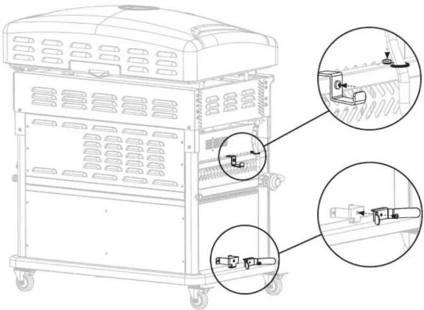
STEP 23 Attach the four (4) side shelf brackets to the sides of the body using eight (8) M6x15 screws (e.). Use one left shelf bracket "A" and one right shelf bracket "B".
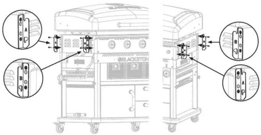
text_image
Technical diagram of a black station device with labeled ports and internal components, showing front and side views with annotations.STEP 24 Unscrew the three (3) M6x8 screws from the side shelf pegs. Use the (3) M6x8 screws to attach the three (3) side shelf pegs to the left side shelf.
natural_image
Technical line drawing of a mechanical support structure with mounting holes and roller supports (no text or symbols)STEP 25 Thread two (2) Short M6 step bolts (i.) into the top holes on the left side shelf. Repeat with the right side shelf.
natural_image
Technical line drawing of a metal bracket with mounting holes and a curved cutout (no text or symbols)CAUTION
- Maximum weight on the side shelf is 10 lbs (4.5 kg).
- The side shelf may get hot while griddle is in use.
STEP 26 Slide the left side shelf onto the side shelf brackets. The threaded M6 step bolts will hook and hold the shelf.
Use two (2) short M6 step bolts (i.), to secure the shelf to the griddle body by screwing them into the bottom holes of the bracket.
Repeat this step with the right side shelf.
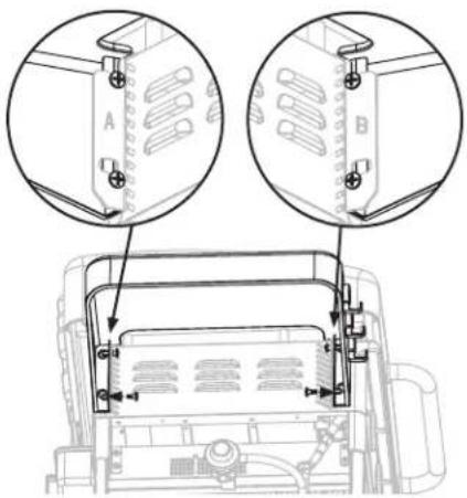
text_image
Technical diagram showing two views of a device with labeled components A and B, including mechanical parts and assembly details.
natural_image
Technical line drawing of a mechanical clamp or bracket assembly with mounting holes and a diagonal cross-section (no text or symbols)Be sure to install handle correctly, with the handle facing down.
STEP 27 Attach the drawer handle by first removing the two small thumb screws from inside the drawer and taking off the front panel of the drawer. Next, use four (4) M5x15 screws (j.) to attach the drawer handle to the front panel. Re-attach the front panel with the previously removed thumb screws. Repeat this step with the other two (2) drawers.

natural_image
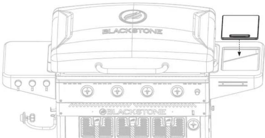
Technical line drawings of two electronic device components: a box with ventilation grating and a mechanical arm (no text or symbols)STEP 28 Place the cutting board onto the right side shelf.
text_image
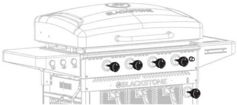
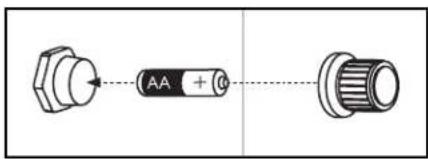
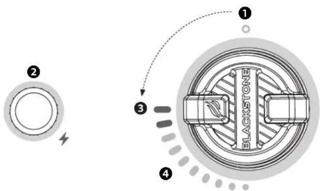
BLACKSTONE BLACKSTONESTEP 29 Install the five (5) control knobs by pushing them into place in the OFF position. Insert one (1) AA battery (not included) under the ignition button.
natural_image
Line drawing of a blackstone gas stove with control knobs and fan (no text or symbols)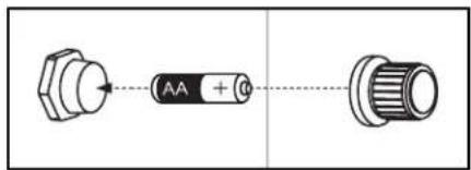
text_image
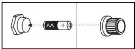
AA + 0Insert one (1) AA battery (not included) into the battery socket with the positive terminal facing out, then screw on the ignitor button until tight. Be careful to not over tighten.
STEP 30 Attach the garbage bag holder using four (4) M5x15 step bolts (c.) onto the right leg assembly.
natural_image
Technical diagram of a server rack with pipe connections and a magnified inset showing internal components (no text or symbols)STEP 31 Turn the paper towel hanger 90 degrees to the usable position.
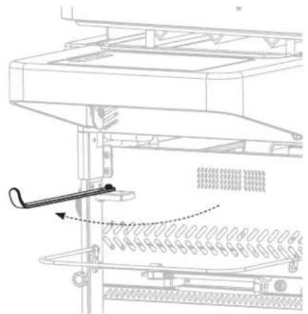
natural_image
Technical line drawing of a mechanical assembly with a tool inserted, showing no text or symbolsSTEP 32 Hang the rear grease cup with aluminum foil liner on the back of the unit.
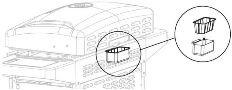
text_image
Diagram showing a printer with a magnified inset of its internal structure, highlighting the component's location.STEP 33 Connect the propane tank (not included) and hook it on the upper propane hanger so that it nestles against the lower propane support. (Please reference the Connection & Removal section of the Fuel chapter.)
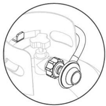
natural_image
Technical line drawing of a mechanical assembly inside a circular frame (no text or symbols)STEP 34 Proceed to the Griddle Seasoning Instructions section of the Care & Maintenance chapter.
Enjoy cooking outdoors on your Blackstone!
ASSEMBLY VIDEOS
View Product Assembly and Technical Support videos online at blackstoneproducts.com/support and on YouTube @BlackstoneGriddles

natural_image
Line drawing of a black stone gas stove with control panel and wheels (no text or symbols)RECIPES FOR THE AIR FRYER
JALAPEÑO CORNBREAD POPPERS
STEP 01 Cook bacon on griddle until done. Once cooled, chop finely and set aside.
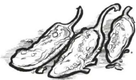
STEP 02 Wash jalapeños and pat dry. Cut in half lengthwise. With a small spoon, scrape the white membranes and seeds away from the jalapeño. Dry jalapeños with a paper towel and set aside.
NOTE: Consider wearing protective rubber gloves when preparing jalapeños.
STEP 03 Make Jiffy corn muffin mix based on manufacturer's directions.
STEP 04 Stir the finely chopped bacon and cheddar cheese into the corn muffin mix.
STEP 05 Preheat air fryer to medium.
STEP 06 Spoon roughly a teaspoon of corn muffin and bacon mix into each jalapeno half. Spread the batter evenly from top to bottom.
NOTE: Resist the temptation to fill the jalapeños with mix, as it can double in size.
STEP 07 Cook the stuffed jalapeños for 8-10 minutes until the cornbread is golden browned and cooked throughout.
STEP 08 Allow to cool.
STEP 09 Using a heat safe ramekin or small baking dish, combine honey and butter and place in the air fryer for 3-5 minutes. Stir frequently until completely melted. Drizzle hot honey butter over jalapeño cornbread bites and serve immediately.
natural_image
Sketch of three eggplants with visible internal structures (no text or symbols)Serves 4-6 | 50 min.
Ingredients
• 12 fresh jalapeños
• 1 box Jiffy cornbread muffin mix
- 6 slices bacon
• 3/4 cup grated cheddar cheese
• 3 tablespoons honey
• 2 tablespoons butter
VIDEO RECIPES:
Find more inspiration and recipes at

blackstoneproducts.com/blogs/recipes

youtube.com/c/ BlackstoneGriddles


@blackstoneproducts
⚠️DANGER
An LPG cylinder not connected for use should NOT be stored in the vicinity of this or any other appliance.
- LPG cylinders should only be stored outside and in a cool, dry place.
- An LPG cylinder should NOT be stored under or near the appliance, in reach of children, or in a building, garage, or any other enclosed area.
- NEVER leave an LPG cylinder inside a vehicle which may become overheated by the sun.
If the information above is not followed exactly, a fire causing death or serious injury may occur.
!DANGER
- NEVER fill an LPG cylinder beyond 80% full.
An overfilled or improperly stored cylinder is a hazard due to possible gas release from the safety relief valve. This could cause intense fire with risk of property damage, serious injury or death.
If you see, smell or hear gas escaping, immediately get away from the LPG cylinder and appliance and call fire department.
FUEL | 20 LB. (9 KG) PROPANE TANK
Section 01
LPG CYLINDER REQUIREMENTS
LPG CYLINDER REQUIREMENTS
The LPG Tank used with your griddle must meet the following requirements:
- Date tested by a LPG supplier within five years of use.
- Size: 18 x 12 in (45 x 30 cm), 20 lb (9 kg).
• Supply system must be arranged for vapor withdrawal. - Tank must include collar to protect LPG Tank valve.
Appliances must be used in accordance with the installation requirements of your gas supply authority, and constructed and marked in accordance with the applicable standard:
- Specifications for LPG Cylinders of the U.S. Department of Transportation (DOT)
• National Standard of Canada, CAN/CSA-B339, Cylinders, Spheres, and Tubes - Specifications for LPG cylinders, Transports Canada (TC), Transportation of Dangerous Goods (TDG)
• Australian Standard AS/NZS 5601
See LPG Tank collar for marking.
LPG TANK VALVE REQUIREMENTS
LPG Tank valve must have:
- Type 1 valve outlet (thread on the outside).
- Safety relief valve.
- UL listed Overfill Protection Device (OPD). This OPD safety feature is identified by a unique triangular hand wheel.
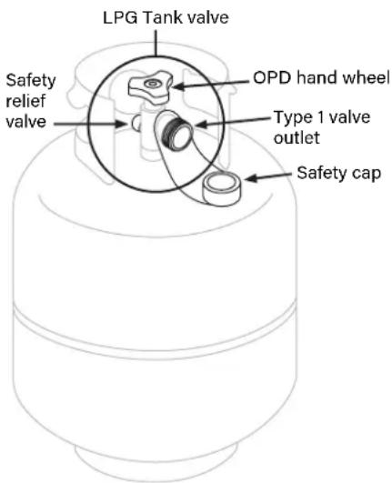
text_image
LPG Tank valve Safety relief valve OPD hand wheel Type 1 valve outlet Safety capAlways keep new and exchanged LPG Tanks in upright position during use, transit or storage.
Section 02
CONNECTION & REMOVAL
REGULATOR SAFETY
If regulator fails in unit, it must be replaced with a Blackstone approved model and must only be replaced by a professionally licensed, authorized dealer. Failure to comply will void the warranty.
CONNECTING THE REGULATOR TO THE LPG TANK Leak test new and exchanged LPG tanks BEFORE connecting to griddle. Please reference the Leak Test Instructions section.
STEP 01 LPG tank must be properly secured to griddle.
(Please reference the Assembly Guide chapter.)
Ensure that the control knobs are turned to OFF.
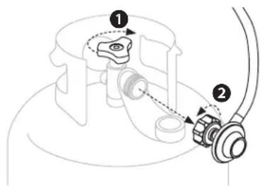
STEP 02 ① Ensure that the LPG tank is OFF by turning the OPD hand wheel clockwise to a full stop.
② Remove the safety cap from the Type 1 valve outlet.
STEP 03 Hold the regulator in a straight line with the Type 1 valve outlet so as not to cross thread the connection.
Center and insert the regulator nipple into the Type 1 valve outlet.
Hand-tighten the coupling nut in a clockwise direction.

text_image
Diagram showing a mechanical or electrical component with numbered parts and directional arrows indicating motion or flow.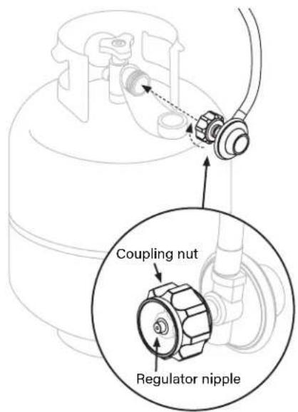
text_image
Coupling nut Regulator nippleWARNING
Keep the fuel supply hose away from any heated surface(s).
WARNING
Never attempt to attach this griddle to the self-contained LPG system of a camper trailer, recreational vehicle or motor home.
Do not use the LPG Tank until it has been leak-tested.
WARNING
The LPG supply cylinder must be disconnected when this appliance is not in use.
WARNING
LPG is highly flammable and may ignite unexpectedly when mixed with air.
CAUTION
LPG is nontoxic, odor-less and colorless when produced. For safety and easy detection, LPG has been given an odor similar to rotten cabbage.
PLEASE NOTE: If connection cannot be completed, disconnect regulator and repeat step 03.
If still unable to complete connection, do not use this regulator!
⚠️DANGER
Do not insert any tool or foreign objects into the valve outlet or safety relief valve. The valve may be damaged resulting in a leak. Leaking propane may result in explosion, fire, severe personal injury, or death.
If a leak is detected at any time, STOP and call the fire department.
If unable to stop a gas leak, immediately close LPG tank valve and immediately contact an LPG gas supplier or fire department.
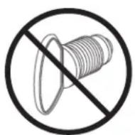
WARNING
Do not insert a POL transport plug (plastic part with external threads) into the Type 1 valve outlet. It will defeat the Safety relief valve feature.
REMOVING THE LPG TANK FOR TRANSPORT/STORAGE
STEP 01 Ensure that the control knobs are turned to OFF.
STEP 02 ① Ensure that the LPG tank is OFF by turning the OPD hand wheel clockwise to a full stop.
② Turn the coupling nut counterclockwise by hand to remove the regulator. (Do not use tools to disconnect.)
STEP 03 Place the safety cap onto the Type 1 valve outlet.
Only use the type of safety cap on the cylinder valve outlet that is provided with the cylinder valve. (Other types of caps or plugs may result in leakage of propane.)
- A disconnected LPG tank in storage or during transportation must have a safety cap installed.
- Failure to use safety cap as directed may result in serious personal injury and/or property damage.
FITTINGS & HOSES
• Annual checking and tightening of metal fittings is recommended.
- Before each use, check to see if hoses are cut or worn.
- Replace damaged hoses before using appliance. (Use only Blackstone approved replacement parts for valve, hose, or regulator.)
text_image
Technical diagram showing mechanical assembly with numbered components and directional arrows indicating motion or connection.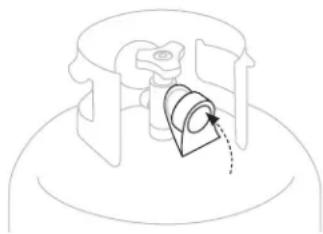
natural_image
Pure mechanical diagram showing a piston-cylinder assembly with no text or symbolsFILLING & EXCHANGE
Use only those reputable exchange companies that inspect, precision fill, test and certify their tanks. LPG dealer must purge new tank before filling.
Volume of propane in tank will vary by temperature. A frosty regulator indicates gas overfill. Immediately close LPG Tank valve and call local LPG gas dealer for assistance.
Do not release liquid propane (LPG) gas into the atmosphere.
To remove gas from LPG Tank, contact a certified LPG dealer or local fire department for assistance.
Exchange tank only for an OPD safety feature-equipped tank.
Section 03
LEAK TEST INSTRUCTIONS
LEAK TEST SAFETY
- Leak test must be repeated each time LPG tank is exchanged or refilled.
• Do not smoke during leak test. - Do not use an open flame to check for gas leaks.
• Appliance must be leak tested outdoors in a well-ventilated area, away from ignition sources such as gas fired or electrical appliances.
• During leak test, keep appliance away from open flames or sparks. - Use a clean paintbrush and a 10/90 mild soap and water solution.
LEAK TEST: LPG TANK
STEP 01 Brush soapy solution onto joint areas of tank. (Indicated by arrows in figure 01.)
Leaks are indicated by growing bubbles.
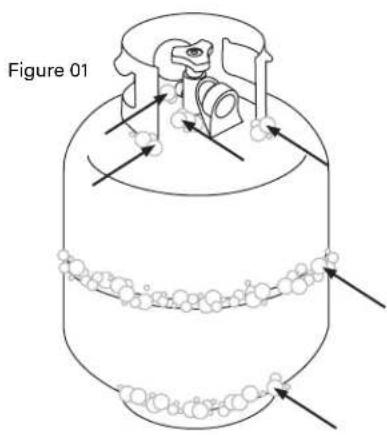
text_image
Figure 01LEAK TEST: VALVES, HOSE & REGULATOR
STEP 01 Ensure that the control knobs are turned to OFF.
Ensure that the regulator is tightly connected to LPG tank.
Completely open the LPG tank by turning the OPD hand wheel counterclockwise.
If you hear a rushing sound, turn gas off immediately. There is a major leak at the connection. Correct before proceeding.
STEP 02 Brush soapy solution onto joint areas of valves and regulator. (Indicated by arrows in figure 02.)
Leaks are indicated by growing bubbles.
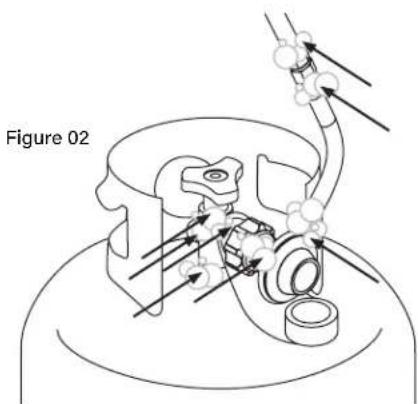
text_image
Figure 02STEP 03 Immediately close the LPG tank by turning the OPD hand wheel clockwise and re-tighten connections. If leaks cannot be stopped DO NOT TRY TO REPAIR.
WARNING
If growing bubbles appear during leak test, do not use or move the LPG bottle. Immediately contact an LPG supplier or fire department.
CAUTION
DO NOT USE HOUSEHOLD CLEANING AGENTS.
Damage to gas valve, hose, and regulator components may result.
NEED HELP?
Register your Blackstone product at blackstoneproducts.com/register and visit us online at
blackstoneproducts.com/support for replacement parts, assembly and operation questions.

WARNING
When not in use, turn unit controls and gas source OFF.
WARNING
The appliance must be isolated from the gas supply piping system by closing its individual manual shutoff valve during any pressure testing of the gas supply piping system at test pressures equal to or less than 1/2 psi (3.5 kPa).
WARNING
This appliance will be hot during and after use. Use insulated oven mitts or gloves for protection from hot surfaces or splatter from cooking liquids.
CAUTION
NEVER handle hot parts with unprotected hands.
CAUTION
DO NOT use Citrisol, abrasive cleaners, de-greasers or a concentrated cleaner on plastic parts. Damage to and failure of parts may result.
CARE & MAINTENANCE
Regularly clean your appliance between uses, especially after extended periods of storage. In order to extend the life and condition of unit, follow best practices detailed in this manual.
Section 01
GENERAL CARE
GENERAL CLEANING
Ensure that the appliance and its components are sufficiently cool before cleaning.
- Clean your appliance often, preferably after each use.
- Be sure to keep the ventilation opening(s) of the cylinder enclosure free and clear from debris.
- Baked-on grease deposits may require the use of an abrasive plastic cleaning pad. Use only in direction of brushed finish to avoid damage.
- DO NOT use abrasive pad on areas with graphics.
- If a bristle brush is used to clean any of the cooking surfaces, ensure no loose bristles remain on cooking surfaces prior to cooking.
PLASTIC PARTS: Wash with warm soapy water and wipe dry.
PAINTED SURFACES: Wash with mild detergent or nonabrasive cleaner and warm soapy water. Wipe dry with soft nonabrasive cloth.
STAINLESS STEEL SURFACES:
To maintain appliance frame's high quality appearance, wash with mild detergent and warm soapy water. Wipe dry with a soft cloth after each use.
AFTER EACH USE
Ensure that any part of the appliance that gets hot and experiences grease build up is cleaned before next use. Otherwise, a fire could occur.
STORAGE
- In order to extend and maintain the life and condition of your appliance, we strongly recommend that the unit be covered when left outside for any length of time, especially during the winter months.
• Take care to always completely dry your appliance before storing and keep away from rain and sprinklers. - Cover the burners with aluminum foil in order to prevent insects or other debris from collecting in the burner holes.
- When gas supply is connected to appliance, store appliance outdoors in a well-ventilated space and out of reach of children.
- Store appliance indoors ONLY if gas supply is turned off, disconnected, removed from appliance and stored outdoors.
- When removing appliance from storage, clean burner assembly before starting appliance. (Please reference the Cleaning the Burner Assembly section.)
VALVE CHECK
Ensure gas is off at the supply shut off valve before checking appliance valves. Knobs must be turned to OFF position.
STEP 01 To check valves, push in knobs and release. Knobs should spring back.
If knobs do not spring back, replace valve assembly before using appliance.
STEP 02 Rotate knobs to LOW position then turn back to OFF position. Knobs should turn smoothly.
COVER FIT GUIDE
Visit us online at
blackstoneproducts.com/support
to find a cover that will fit your appliance.

text_image
QR code image containing encoded data, no visible human-readable textWARNING
Ensure that the fuel nozzle is housed within the burner opening.
natural_image
Architectural floor plan showing room layouts and structural elements (no text or labels)Section 02
CLEANING THE BURNER ASSEMBLY
Unit burners vary, however these instructions apply to all units. Clean burner assembly and check burner for damage. If any large cracks or holes are found, replace burner.
STEP 01 Ensure that the gas is turned OFF at control knobs and gas supply. Remove the cooking top.
STEP 02 Carefully detach and remove the burner.
natural_image
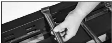
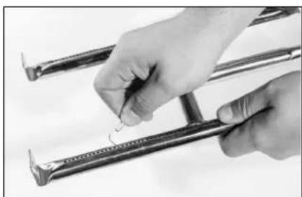
Close-up of a hand adjusting metal brackets on a black metal frame (no text or symbols visible)STEP 03 Run a narrow bottle brush through each burner tube several times. (DO NOT use wire brushes)
Additional Methods Include:
a Run a stiff wire bent into a small hook through each burner tube several times.
b Use an air hose to force air into burner tube and out burner ports. Check that air blows through each hole. (Wear eye protection)

natural_image
Close-up of a hand holding a screwdriver tip, no visible text or symbolsVIDEO TUTORIAL
How to Clean Your Burner Tube | Blackstone Griddle

text_image
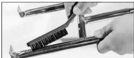
ONL CIRCUITING INSTRUCTIONS 1. Make of instruction 2. Open hands during TV 3. Apply to the computer 4. Turn the control panel 5. Attach the remote 6. If you want to use or off with a console, then 7. Use your computer to use 8. Replace information on the screen 9. Use your computer to use 10. Use your computer to use 11. Use your computer to use 12. Use your computer to use 13. Use your computer to use 14. Use your computer to use 15. Use your computer to use 16. Use your computer to use 17. Use your computer to use 18. Use your computer to use 19. Use your computer to use 20. Use your computer to use 21. Use your computer to use 22. Use your computer to use 23. Use your computer to use 24. Use your computer to use 25. Use your computer to use 26. Use your computer to use 27. Use your computer to use 28. Use your computer to use 29. Use your computer to use 30. Use your computer to use 31. Use your computer to use 32. Use your computer to use 33. Use your computer to use 34. Use your computer to use 35. Use your computer to use 36. Use your computer to use 37. Use your computer to use 38. Use your computer to use 39. Use your computer to use 40. Use your computer to use 41. Use your computer to use 42. Use your computer to use 43. Use your computer to use 44. Use your computer to use 45. Use your computer to use 46. Use your computer to use 47. Use your computer to use 48. Use your computer to use 49. Use your computer to use 50. Use your computer to use 51. Use your computer to use 52. Use your computer to use 53. Use your computer to use 54. Use your computer to use 55. Use your computer to use 56. Use your computer to use 57. Use your computer to use 58. Use your computer to use 59. Use your computer to use 60. Use your computer to use 61. Use your computer to use 62. Use your computer to use 63. Use your computer to use 64. Use your computer to use 65. Use your computer to use 66. Use your computer to use 67. Use your computer to use 68. Use your computer to use 69. Use your computer to use 70. Use your computer to use 71. Use your computer to use 72. Use your computer to use 73. Use your computer to use 74. Use your computer to use 75. Use your computer to use 76. Use your computer to use 77. Use your computer to use 78. Use your computer to use 79. Use your computer to use 80. Use your computer to useSTEP 04 Brush entire outer surface of burner to remove grime.
natural_image
Close-up of hands using a tool to adjust or install a mechanical component (no visible text or symbols)youtube.com/ watch?v=xKQTCrFCzf8

STEP 05 Clean any blocked ports with stiff wire such as an open paper clip. Then, carefully replace burners and reattach.
VERY IMPORTANT: Burner tubes must be reengaged with the valve openings.
natural_image
Close-up of hands holding a metal tool with a small wire, no visible text or symbolsBURNER MAINTENANCE
In most circumstances, burning residue off after cooking will keep burner clean.
- Ensure that the flow of combustion and ventilation air is not obstructed.
- Burner should be removed and cleaned annually or whenever heavy build-up or insects/insect nests are found in order to ensure that there is no blockage in the burner portholes or venturi tubes.
- Use pipe cleaner to clear obstructions. A wire brush may be used to remove corrosion from the burner surfaces.
MATCH LIGHTING INSTRUCTIONS
Before beginning, check for gas leaks. (Please reference the Leak Test Instructions in the Fuel chapter.)
STEP 01 Ensure control knob is in OFF position.
STEP 02 Remove cooking top.
STEP 03 Light a match (or long lighter) no shorter than 11 inches long. Place the flame on the right or left side of the burner.
STEP 04 Push in and turn the control knob to the HIGH position. Ensure burner lights and stays lit.
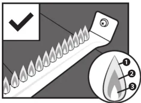
BURNER FLAME CHECK
Always check burner flame before use.
STEP 01 Light burners and rotate knobs from high to low. When knob is at high, flames should be larger than when knob is at low.
STEP 02 Perform burner flame check by looking below cooking top on the side of unit to view burners below.
If there is a sudden drop or low flame issue, please reference the Troubleshooting chapter.
WARNING
A clogged burner tube can lead to a fire beneath the appliance.
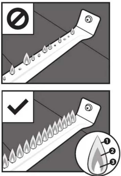
text_image
No ✓ 1 2 3Healthy flames might have a few flickers of yellow color ①, then a dark blue color ②, followed by a vibrant blue by the burner tube ③.
VIDEO TUTORIAL
How to Season a New Blackstone Griddle | Blackstone Griddle

text_image
BLACKSTONE CHEF NATHAN LIPPY 0.01 / 5/26youtube.com/ watch?v=VspmDVnj2pl&t=3s

PLEASE NOTE: Small variations in manufacturing and raw materials can cause some griddles to be slightly warped. A slight warp will disappear when the griddle is heated in preparation for cooking.
natural_image
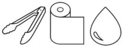
Three simple line drawings: a pair of tongs, a rolled document, and a droplet (no text or symbols)TOOLS NEEDED: Cooking tongs, Paper towels, and Cooking oil
Section 03
GRIDDLE SEASONING INSTRUCTIONS
For best results, we recommended seasoning the griddle before cooking on griddle top.
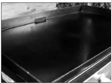
STEP 01 Make sure griddle top is wiped clean of debris. (For first time cleaning, please reference the Cleaning Your Griddle Top section.)
Blackstone griddle tops are pre-treated with soy oil as a protective coating. This coating may leave a discoloration on the griddle top. This is normal and will not affect the seasoning process.
STEP 02 Set your griddle to high heat until your griddle top changes color. Use tongs to hold a paper towel or cotton cloth and spread 2-3 tablespoons of your seasoning oil across the griddle surface.
When seasoning your griddle top, remember to use a thin and even layer of oil—the thinner the layer of oil, the easier it will be to burn it off.
STEP 03 You will know it is done when it stops smoking. You will want to repeat this 3-4 times for your initial seasoning.
The heat of the griddle will break down the oil and bond it to the metal, creating a new polymer that acts as a stick resistant and protective layer over the griddle.
natural_image
Hand cleaning a clean surface on a dark tray (no text or symbols visible)
natural_image
Black stone ship with a small boat floating on water, no visible text or symbols
natural_image
Close-up of a hand using a tool to clean or store food on a dark surface, with steam rising in the background (no text or symbols visible)
natural_image
Close-up of a textured surface with indistinct patterns and no visible text or symbolsWHY DO I NEED TO SEASON MY GRIDDLE?
Seasoning leaves a hard protective layer bonded to the steel surface.
• Natural stick resistance.
• Prevents rust and corrosion.
natural_image
Close-up of a dark, glossy metal container or tank with a flat lid and rectangular base (no visible text or symbols)CAUTION
Customers in humid or coastal climates may require more frequent seasonings and the use of heavier cooking oils to avoid rusting and corrosion.
GRIDDLE SEASONING TROUBLESHOOTING SYMPTOMS
- After seasoning, there is a brownish residue on the griddle surface.
POSSIBLE CAUSES SOLUTION
| 01. Too much oil was used. | First, turn your griddle on high and let it heat for 10-15 minutes. |
| 02. You turned off the heat too soon. | Next, scrape off as much of the thickened and partially cooked oil as you can.Then, re-season with a very thin layer of oil. |
SYMPTOMS
- After seasoning, the griddle surface is not black.
- Food is sticking to the griddle surface.
POSSIBLE CAUSES SOLUTION
| 01. The corners and edges do not have the same access to the direct heat of the burners, making it harder for the seasoning to darken like the rest of the griddle top. | Apply a thin layer of oil between cooks to maintain seasoned cooking surface. (Please reference the Cleaning your Griddle Top section.)After using your griddle for multiple cooks, the seasoning will even out and improve. |
For further troubleshooting,
please reference the
Troubleshooting chapter.
For Frequently asked questions, visit
blackstoneproducts.com/faq
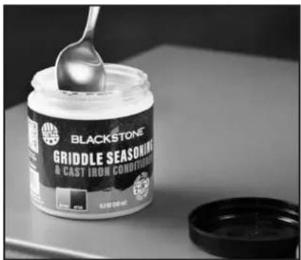
WHAT OIL IS BEST TO USE?
The Blackstone Seasoning and Cast Iron Conditioner is the best and easiest way to get consistent results. This unique blend of oils combines the best of many different cooking oils.
natural_image
Blackstone griddle seasoning jar with a spoon, placed on a tray with a lid (no visible text or symbols)Can I use any food grade oil?
Yes, but different oils can vary in the process from the burn time, smoke point, and durability once finished.
If you prefer to use an animal fat for seasoning, only use rendered fat (pure tallow, schmaltz, etc.) with no additives.
DANGER
DO NOT place flammable items on side shelves near the griddle. Aerosol containers are particularly hazardous because they can overheat and result in an explosion, fire, severe personal injury, or death.
WARNING
DO NOT place oily or greasy towels near the griddle unit as they can spontaneously combust.
CAUTION
The grease cup must be removed and emptied after each use.
Do not remove the grease cup until the griddle has completely cooled.
FOR EVERY GRIDDLE SURFACE
The Blackstone Griddle Degreaser and Cleaning Spray is gentle enough to clean every surface of your griddle. Use it on the griddle top, the griddle frame, or anywhere that experiences a build up of grease.

natural_image
Close-up of a hand using a black cleaning brush (no visible text or symbols)Section 04
CLEANING YOUR GRIDDLE TOP
Follow these simple cleaning steps to ensure optimal performance and longevity of your Blackstone Griddle.
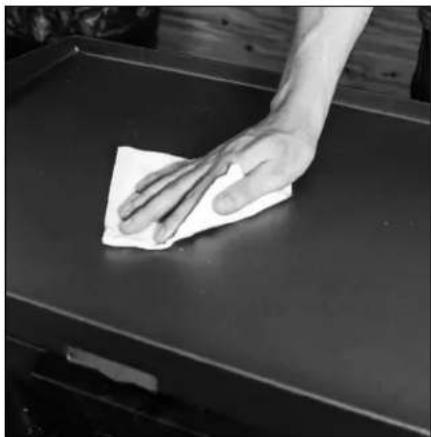
STEP 01 To clean griddle after each use, cool griddle below 300° F. Scrape food debris with spatula or straight metal scraper.
STEP 02 Wipe down griddle surface with paper towel.
STEP 03 Divide griddle surface into approximately 6" sections (width of scraper tool). Apply a small amount of water onto first section with a bottle and then scrape the water and debris toward the grease trap. Move to the next 6" section and repeat.
DO NOT USE MORE THAN TWO TABLESPOONS OF WATER AT A TIME.
(For stuck-on food residue, use a bit of coarse salt.)
STEP 04 Wipe again with a paper towel and dry completely.
STEP 05 Apply thin coat of cooking oil to maintain seasoning and protect the griddle top.

natural_image
Close-up of a hand using a power tool to cut a metal sheet (no text or symbols visible)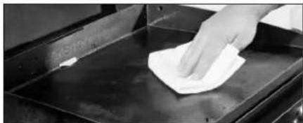
natural_image
Hand cleaning a white cloth on a metal tray (no text or symbols visible)
natural_image
Close-up of a hand pouring liquid from a bottle into a black stone griddle (no visible text or symbols)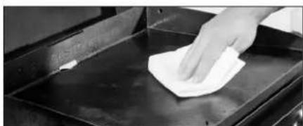
natural_image
Hand cleaning a metal tray with a cloth (no text or symbols visible)
natural_image
Close-up of a hand using a tool to apply material to a metal component (no visible text or symbols)FIRST TIME CLEANING
Blackstone Griddles are pre-treated with cooking oil to prevent rust and damage during shipping. For first time use, wash griddle with hot, soapy water.
Rinse and dry completely. Proceed with seasoning instructions. (Please reference the Griddle Seasoning Instructions section.)
PROTECTING YOUR GRIDDLE TOP
Store griddle in a cool, dry location. Always cover griddle if stored outdoors. Choose from a variety of griddle covers offered by Blackstone.
When protecting griddle with soft cover, use the "tenting" method to prevent water from accumulating on griddle top. "Tenting" involves placing an object (a bowl, tennis ball or PVC pipe) beneath soft cover in the center of griddle in order to allow water to slide off. "Tenting" helps prevent rust.
CUTTING ON THE GRIDDLE TOP
Using a knife directly on the surface of the griddle will not harm the griddle top.
REMOVING RUST
If rust appears on the griddle surface, rub it off with steel wool, low grit sandpaper or the Blackstone Pumice Stone and re-season the surface.
Recovering your Blackstone Griddle Top
natural_image
Hand pressing a button on a black square object, no visible text or symbolsyoutube.com/
watch?v=thPE2IgnSil

WARNING
NEVER APPLY COLD WATER ACROSS THE WHOLE SURFACE OF A HOT GRIDDLE AT ONCE. This may cause warping.
Adding a large amount of cold or frozen food (or food with significant water content) to a hot griddle may cause griddle to warp.
CAUTION
DO NOT USE SOAP ON THE GRIDDLE COOKING SURFACE. This will destroy the griddle's seasoning.
ASSEMBLY VIDEOS
View Product Assembly and Technical Support videos online at blackstoneproducts.com/support and on YouTube @BlackstoneGriddles

WARNING
Do not clean the air fryer unit with a water spray or the like.
Section 05
CLEANING YOUR AIR FRYER
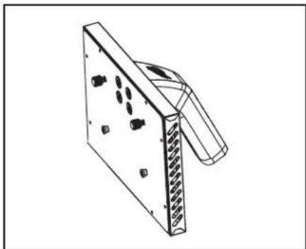
Your air fryer drawer is dishwasher safe. You will need to remove the handle assembly prior to placing in the dishwasher.
natural_image
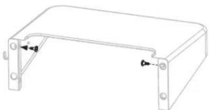
Technical line drawing of a mechanical bracket with mounting holes and a side clip (no text or symbols)Keep the handle assembly with your Griddle, reassemble after the fryer drawer is clean and dry.
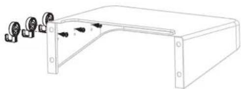
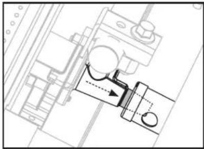
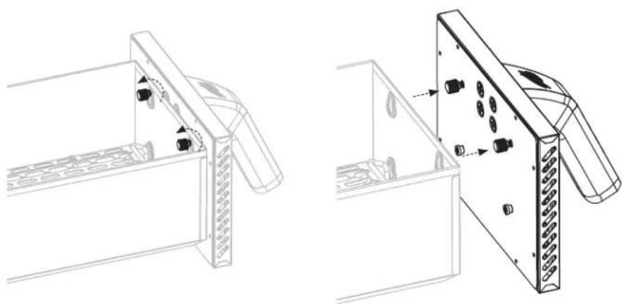
STEP 01 Loosen the top two (2) thumb screws and lift the handle assembly to remove from the fryer drawer. Do not remove the thumbscrews.
natural_image
Technical line drawing of a mechanical assembly with two views (top and side), showing internal components and mounting holes (no text or symbols)STEP 02 Remove the trivet from the air fryer drawer by lifting from the trivet handle up and out of the fryer drawer.
natural_image
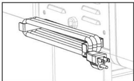
Technical line drawing of a mechanical assembly with no visible text or symbolsWrap the power cord around the power cord bracket when the air fryer is not in use.
natural_image
Isometric line drawing of a rectangular enclosure with internal grid pattern and mounting bracket (no text or symbols)IGNITION | AIR FRYER
PROPANE AIR FRYER OPERATION
For proper ignition and operation of the air fryer follow the steps below.
STEP 01 In order for the ignitor button to work properly, ensure that the battery is installed correctly.
STEP 02
① Ensure that the fryer control knob is turned to OFF.
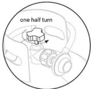
STEP 03 Ensure that the LPG tank is properly connected to the unit. Turn gas ON at the LPG cylinder by slowly turning the OPD handwheel halfway.
text_image
AA + 0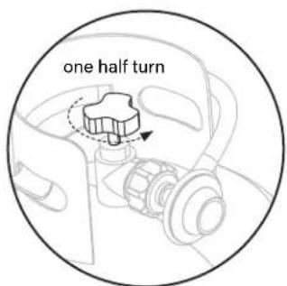
text_image
one half turnSTEP 04
② Push and hold the ignitor button.
3 Push and turn the fryer control knob counter-clockwise to MAX. (Release the ignitor button when the burner lights.)
④ Adjust the temperature to desired level.
LOW: 300^ F - 375^ F
MED: 375^ F - 425^ F
HIGH: 425^ F - 475^ F
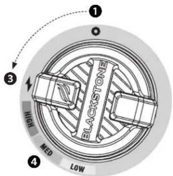
text_image
1 BLACKSTONE 3 HIGH MED LOW 4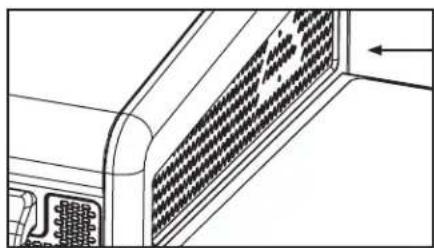
natural_image
Technical line drawing of a computer ventilation grille with no visible text or symbolsTo verify that the air fryer burner has lit, look into the burner chamber from the right side of the unit.
STEP 05 Push the rocker switch to power ON, the blower fan will start immediately.

WARNING
Do not lean over the appli- ance while lighting.
WARNING
If ignition does NOT occur in 5 seconds, turn burner controls OFF, wait 5 minutes and repeat lighting procedure.
If burner does not ignite with open valve, gas will continue to flow out of burner and could accidentally/inadvertently ignite with risk of injury.
IGNITION | BATTERY POWERED
For proper ignition and operation of the appliance follow the steps below.
STEP 01 In order for the ignitor button to work properly, ensure that the battery is installed correctly.
STEP 02
① Ensure that the control knob is turned to OFF.
text_image
AA + 0STEP 03 Ensure that the LPG tank is properly connected to the unit. Turn gas ON at the LPG cylinder by slowly turning the OPD handwheel halfway.
text_image
one half turnSTEP 04
② Push and hold the ignitor button.
③ Push and turn the control knob counter-clockwise to HIGH. (Release the ignitor button when the burner lights.)
④ Adjust the temperature to desired level.
text_image
Diagram illustrating a process of battery charging with labeled steps and components including a blackstone component.TROUBLESHOOTING
Visit BLACKSTONEPRODUCTS.COM/SUPPORT for additional troubleshooting.
Section 01
BATTERY POWERED IGNITION
SYMPTOMS
- Burner will not Light with ignition system
- Pressing the ignitor button does not result in a clicking sound
If ignition does not occur in 5 seconds, turn the burner controls off, wait 5 minutes and repeat the lighting procedure.
If this does not work, to determine the cause, please try to ignite your griddle with a match. (Please reference the Match Lighting Instructions in the Cleaning the Burner Assembly section of the Care & Maintenance chapter.)
If you CAN ignite your griddle with a match
POSSIBLE CAUSES SOLUTION
- Dead battery or no battery. Replace with new battery.
- Battery installed incorrectly. Ensure that the battery is installed negative end first.
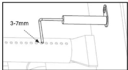
- Ignitor wire misaligned. Ensure that the ignition needle is positioned 1/8" to 1/4" away from the burner tube, positioned above a burner hole.
- Damage to the ignition system. Contact customer service for replacement parts.
If you CAN NOT ignite your griddle with a match
POSSIBLE CAUSES SOLUTION
- Burner tubes are not receiving fuel. Please reference the Gas Flow section of the Troubleshooting Chapter.

text_image
AA + 0Insert one (1) AA battery (not included) into the battery socket with the positive terminal facing out, then screw on the ignitor button until tight. Be careful to not over tighten.
text_image
3-7mmEnsure that the ignition needle is positioned 3-7mm away from the burner tube, positioned above a burner hole.
Section 02
GAS FLOW
natural_image
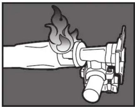
Illustration of a fire extinguisher with flame and valve (no text or symbols)SYMPTOMS
- A flame is coming out of the air gate.
POSSIBLE CAUSES SOLUTION
- Something is blocking the venturi in the burner tube. This is not allowing the propane to flow through the burner, causing the flame to back out the air gate.
Clean the burner assembly to remove the obstruction. (Please reference the Cleaning the Burner Assembly section of the Care & Maintenance chapter.)
text_image
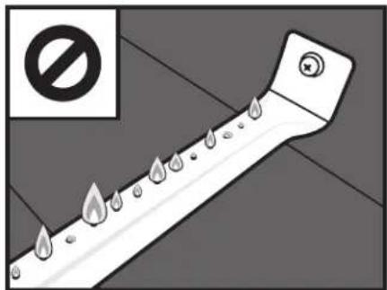
Safety warning sign with pictogram of a fire extinguisher and prohibition symbolSYMPTOMS
- Burner flames are yellow or irregular.
POSSIBLE CAUSES SOLUTION
- Something is blocking the air gate for the burner. This is blocking oxygen from mixing with the propane correctly to get healthy flames.
Check the air gates in your burner. If you have adjustable air shutters over your air gates, make sure that they are completely open. If your burners have bug shields, clean any spider webs, soot, or debris off the bug shield. Clean any other obstructions out of air gates.
TECHNICAL SUPPORT:
Scan QR code for more videos or visit the Blackstone YouTube channel at youtube.com/blackstonegriddles

SYMPTOMS
- Appliance will not achieve a high heat or heats unevenly.
- Burner flames start strong, then immediately drop to low even when burner is set to high position.
- Flame height drops when a second burner is lit.
- Flames do not extend the full length of the burner, or only run on one side of the burner.
- Burner flames are inconsistent.
POSSIBLE CAUSES SOLUTION
| 01. United States regulations require that all regulators contain a flow limiting device for consumer safety. This device measures the amount of propane going through the regulator to ensure the levels are safe. If the flow rate through the regulator is too high (a symptom of a large leak), the flow limiting device will trigger, restricting the flow of propane to reduce the chance of a dangerous fire. This safety system can accidentally be tripped by opening a propane tank too quickly or opening the propane tank when a burner knob is not in the off position. |
This safety system can be reset by moving the burner knobs to the off position, closing the propane tank, and disconnecting the regulator from the propane tank. Wait five minutes to allow the pressure to dissipate, then reconnect the regulator to the propane tank and slowly open the OPD handwheel one half turn. Ignite your appliance as described in the Care & Maintenance chapter.
-
LP gas cylinder is empty or low. Refill or replace the propane tank.
-
Obstructions in the burner, gas jets, or fuel rail.
Clean the burner, jets, and gas hose. (Please reference the Cleaning the Burner Assembly section of the Care & Maintenance chapter.)
- Regulator stuck in safety position. Contact customer service for replacement parts.
BURNER FLAME PATTERN
Your appliance's burners are designed to mix oxygen and propane at a rate that allows for optimal flames. Should the burner's holes, air gate, or venturi get blocked, it will affect the propane and air mixture, causing low or inconsistent flames, or flames coming from the air gate.
text_image
Diagram illustrating a droplet with three labeled parts (1, 2, 3) and a checkmark, likely illustrating a droplet detection or cleaning process.Healthy flames might have a few flickers of yellow color ①, then a dark blue color ②, followed by a vibrant blue by the burner tube ③.
natural_image
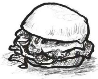
Sketch of a hamburger with visible bun, scallions, and toppings (no text or symbols)Serves 4 | Ⓞ 7 min.
Ingredients
• 1/2 lb of 80/20 ground beef
• 1 Vidalia (or sweet) onion (sliced paper thin)
• 4 slices American cheese
• 1/4 cup of dill pickle chips
- Salt
RECIPES FOR LUNCH & DINNER
OKLAHOMA FRIED ONION BURGER
STEP 01 Pre-heat your Blackstone to high heat.
STEP 02 Make four (4) 2 oz loosely packed meatballs with the ground beef and place on the hot griddle. Add a pinch of salt over each and using your Blackstone Burger Press, smash them very thin.
STEP 03 Add 2-3 ounces of thinly sliced onion over each patty.
STEP 04 Cook for 60-90 seconds and flip so that the onions are under the patty. Add 1 slice of American cheese to each patty and then place the top bun over the cheese and then the bottom bun on top of the top bun. Cook for another 60 seconds.
STEP 05 To plate, remove the bottom bun from the top and set on plate. Use your spatula to lift the burger with top bun and add to the bottom bun.
STEP 06 Serve hot with a few dill pickle chips.
VIDEO RECIPES:
Find more inspiration and recipes at

blackstoneproducts.com/blogs/recipes

youtube.com/c/BlackstoneGriddles


@blackstoneproducts
RECIPES FOR BREAKFAST
STRAWBERRIES AND CREAM PANCAKES
Recipe by Danielle Zechmann
STEP 01 Separate egg and whisk egg white until stiff peaks form. Set aside.
STEP 02 Make your cream cheese filling. Whisk together cream cheese, sugar, and lemon juice. Then, turn to low speed and add in whipped cream. Set aside.
Cream Cheese Filling
• 8 oz cream cheese, room temperature
• 3 tbsp sugar
• 2 tbsp lemon juice
• 2/3 cup whipping cream
STEP 03 Get your strawberry syrup started. In a sauce pan add chopped strawberries, sugar, lemon juice and simmer on the griddle top or side burner until juices have slightly thickened. (About 20-25 mins.)
Strawberry Syrup
- 1 pint of strawberries cut into chunks (frozen is okay)
• 1/4 cup sugar
• 2 tbsp lemon juice
STEP 04 In a mixing bowl, combine all dry pancake ingredients.
STEP 05 In a separate bowl, mix egg yolk, milk, lemon juice, ricotta, butter, and vanilla.
STEP 06 Slowly add dry ingredients and mix until combined.
STEP 07 Gently fold the egg whites and strawberry bits into the pancake mix.
STEP 08 Preheat Griddle to medium. Melt a tablespoon of butter on griddle and spread around. Pour 1/4 cup of pancake mix onto griddle and let cook until bubbles start to form and edges are slightly browned. About 3-4 minutes. Flip and cook another 3 minutes.
STEP 09 Once all of your pancakes are cooked, grab a plate and start layering your pancakes. Begin with a pancake, then spread some of the cream cheese filling, and top with the strawberry syrup.

natural_image
Sketch of layered dessert with strawberries and toppings (no text or symbols)Serves 6 | ⚙ 45 min.
Pancake Ingredients
- 1 egg, separated
• 1/2 cup milk
• 1/3 cup ricotta cheese
• 2 tbsp melted butter - 1 tsp pure vanilla extract
• 2 tsp lemon juice - 5 strawberries chopped into bits (frozen is okay)
DRY INGREDIENTS
• 2/3 cup all purpose flour
• 2 tsp baking powder
• 1 tbsp sugar
- a pinch of salt
VIDEO RECIPES:
Find more inspiration and recipes at

blackstoneproducts.com/blogs/recipes

youtube.com/c/ BlackstoneGriddles


@blackstoneproducts
natural_image
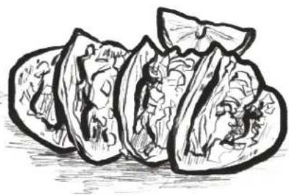
Sketch of sliced lettuce showing whole and cross-section (no text or symbols)RECIPES FOR LUNCH & DINNER
TACOS BORRACHOS
Serves 4 | 2 - 4 hours
Ingredients
• 12 oz of blond beer
• 2 lb of sirloin steak
• 1 bunch cilantro (finely chopped)
• 1/4 white onion (finely chopped)
• 1/4 tablespoon of black pepper
• 4 garlic cloves (chopped in big chunks)
• 1/4 cup of vegetable oil
• 24 tortillas (small, 4.5" tortillas)
- Salt (to taste)
STEP 01 Season the sirloin steaks with salt and black pepper, making sure that you rub the salt and pepper well into the steaks.
STEP 02 Slice the steak into small pieces.
STEP 03 In a plastic bag, place the steak pieces, onions, garlic, and cilantro. Mix all ingredients together.
STEP 04 Once all ingredients are mixed, add little by little the content of the bottle of beer (cold or room temperature) into the plastic bag.
STEP 05 Take the air out of the plastic bag and let the meat marinade in the refrigerator between 2 and 4 hours.
STEP 06 When the meat is ready, drain the beer and place the meat on a plate.
STEP 07 Pre-heat the Blackstone griddle at medium heat for five minutes. Then, add vegetable oil to the surface and let it get to temperature for thirty seconds. Add your previously marinated steak to the Blackstone griddle.
STEP 08 Cook the steak for about three minutes or until the steak is thoroughly cooked, and place in a bowl.
STEP 09 Spread all remaining steak juices in the griddle, and place the tortillas on top until the tortillas are cooked (the tortillas change color slightly and they become malleable), turning the tortillas from time to time.
STEP 10 To make the tacos, place one tortilla on top of the other (two tortillas together). With a spoon place the steak on top of the tortillas and garnish with white finely chopped onion and cilantro. You can also add your favorite salsa as well.
VIDEO RECIPES:
Find more inspiration and recipes at

blackstoneproducts.com/blogs/recipes

youtube.com/c/BlackstoneGriddles


@blackstoneproducts
NORTH ATLANTIC IMPORTS LLC 1-YEAR WARRANTY
North Atlantic Imports, the manufacturer, will warranty for one year from purchase all parts, workmanship, and finishes. It will be the manufacturer's option as to whether to repair or replace any of the above items. All warranties are limited to the original purchaser only. This warranty does not cover any liability on the part of North Atlantic Imports, its agents or employees, for any indirect or consequential damages for breach of warranty. The purchaser must follow the manufacturer's usage instructions.
Under no circumstances is the manufacturer responsible for damages from the failure to operate the cooking station properly. It is the responsibility of the purchaser to establish the warranty period by verifying the original purchase date with original sales receipt.
For more detailed explanation of the warranty, read below:
North Atlantic Imports LLC warrants to the owner that the product covered by this agreement is free from defects in material and workmanship under normal use and service for which it was intended if, but only if, it has been operated in accordance with North Atlantic Imports LLC instructions exclusively for domestic use, and not for private or public club, institutional or commercial purposes.
North Atlantic Imports LLC's obligation under this warranty is limited to replacing or repairing, free of charge, any part or parts that may prove, to the satisfaction of North Atlantic Imports LLC, to be defective under normal home use and service within the following stated periods of time from the date of purchase; for one year from purchase, all parts, finish, and workmanship. Should any failure to conform to this warranty become apparent during applicable warranty periods stated above, the original purchaser must notify North Atlantic Imports LLC of breach of warranty within the applicable warranty period.
North Atlantic Imports LLC shall upon notice and compliance by the original purchaser with such instructions, correct such nonconformity by repair or replacement of the defective part or parts.
Correction in the manner provided above shall constitute a fulfillment of all obligations of North Atlantic Imports LLC with respect to the quality of the product.
North Atlantic Imports LLC does not warrant this equipment to meet the requirement of any safety code of any state, municipality or other jurisdiction, and the original purchaser assumes all risk and liability whatsoever resulting from the use thereof, whether used in accordance with North Atlantic Imports LLC instructions or otherwise.
This warranty does not cover and is intended to exclude any liability on the part of North Atlantic its agents, servants or employees whether under this warranty or implied by law for any indirect or consequential damages for breach on any warranty. The purchaser must
establish all applicable warranty periods pursuant to this warranty by verifying the original purchase date by producing the dated sales receipt. This warranty shall not apply to this product or any other part thereof which has been subject to accident, negligence, alteration, abuse, or misuse or which has been repaired or altered without North Atlantic written consent, outside of North Atlantic Imports LLC factory. The full manufacturer warranty is not valid for griddles purchased from unlicensed, third-party resellers, purchased at a discount due to missing or damaged parts, or purchased as a floor model; at the discretion of North Atlantic Imports.
North Atlantic Imports LLC makes no warranty whatsoever in respect to accessories or parts not supplied with it. This warranty shall apply only within the boundaries of the United States of America. This warranty gives the original purchaser specific rights, and the original purchaser may also have other rights, which vary from state to state.
MANUEL D'UTILISATION
Modèle 1923 v13
PLAQUE CHAUFFANTE DE 36 PO
AIRFRYER COMBO

Intertek
5015923
CONFORME À ANSI STD. Z 21.89-2017
text_image
BLACKSTONE BLACKSTONEnatural_image
Line drawings of two types of wrenches: a standard screwdriver and an adjustable wrench (no text or symbols present)OUTILS NÉCESSAIRES:
natural_image
Line drawing of a cylindrical battery with a separate 2.5A batteries shown in opposite directions (no text or symbols)NON INCLUS:
natural_image
Technical line drawing of a rectangular frame with four circular components attached (no text or symbols)natural_image
Technical line drawing of a modular cart or pallet assembly with wheels and structural supports (no text or symbols)natural_image
Technical line drawing of a mechanical cart with wheels and support legs (no text or symbols)natural_image
Technical line drawing of a rectangular frame with vertical supports and wheels, no text or symbols presentnatural_image
Technical line drawing of a mechanical frame with vertical supports and mounting holes (no text or symbols)natural_image
Technical line drawing of a mechanical cart with wheels and a handle (no text or symbols)natural_image
Technical line drawing of a server rack with labeled components and mounting hardware (no readable text or symbols)natural_image
Line drawing of a multi-tiered industrial machine with wheels and ventilation slots (no text or symbols)natural_image
Technical illustration of a mechanical device with a magnified inset showing a moving cart on a surface (no text or symbols present)natural_image
Technical line drawing of a mechanical device with a magnified inset showing internal components (no text or symbols)natural_image
Simple line drawing of a rectangular panel with two wheels and an attached curved arm (no text or symbols)text_image
BLACKSTONE ① ②natural_image
Pure diagram of a rectangular frame with vertical arrows and dots, no text or symbols presentnatural_image
Technical line drawing of a rectangular device with mounting holes and a curved handle (no text or symbols)text_image
BLACKSTONE BLACKSTONEnatural_image
Technical line drawing of a mechanical component with a curved arrow indicating direction (no text or symbols)text_image
Technical diagram of a blackstone industrial machine with labeled components and close-up insets showing internal wiring connections.natural_image
Technical line drawing of a mechanical device with an inset close-up showing internal components (no text or symbols)natural_image
Technical line drawing of a mechanical device with three circular insets showing close-ups of components (no text or symbols)natural_image
Technical line drawing of a mechanical component with mounting brackets and a circular emblem (no text or symbols)text_image
Technical diagram of a black station module with labeled ports and connectors, showing front and side views with annotations.natural_image
Technical line drawing of a mechanical assembly with mounting flanges and hanging weights (no text or symbols)natural_image
Technical line drawing of a metal bracket with mounting holes and a curved top surface (no text or symbols)ATTENTION
text_image
Technical diagram showing two views of a device with labeled components A and B, including a close-up view of the component.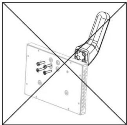
natural_image
Technical line drawing of a mechanical clamp or bracket assembly with mounting holes and a diagonal cross-section (no text or symbols)natural_image
Technical line drawings of two electronic device components: a box with internal structure and a mechanical arm assembly (no text or symbols)text_image
BLACKSTONE BLACKSTONEnatural_image
Line drawing of a blackstone gas stove with control knobs and ventilation slots (no text or symbols)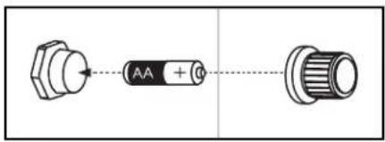
text_image
AA + 0natural_image
Technical diagram showing a pipe connection mechanism inside a server rack, with an inset magnified view of the component (no text or symbols present)natural_image
Technical line drawing of a mechanical device with a lever and gear mechanism (no text or symbols)natural_image
Diagram of a computer monitor with two circular insets showing internal components (no text or symbols)natural_image
Technical line drawing of a mechanical assembly inside a circular frame (no text or symbols)natural_image
Line drawing of a black stone gas stove with control panel and wheels (no text or symbols)RECETTES POUR LA FRITEUSE À AIR
POPPERS DE PAIN DE MAÏS AU JALAPEÑO
natural_image
Sketch of three eggplants with visible internal structures (no text or symbols)Pour 4-6 | ⏻ 50 minutes
Ingrédients
blackstoneproducts.com/blogs/recipes

youtube.com/c/ BlackstoneGriddles


@blackstoneproducts
⚠️DANGER
text_image
Technical diagram showing mechanical assembly with labeled parts 1 and 2, likely illustrating a valve or actuator mechanism.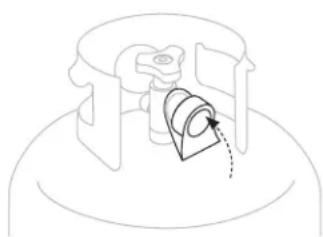
natural_image
Pure mechanical diagram showing a piston-cylinder assembly with no text or symbolsREMLISSAGE & ÉCHANGE
text_image
Figure 02blackstoneproducts.com/register
blackstoneproducts.com/support
blackstoneproducts.com/support
text_image
QR code image containing encoded data, no visible human-readable textATTENTION
natural_image
Technical line drawing of a mechanical assembly with no visible text or symbolsSection 02
NETTOYAGE DU BRÛLEUR
natural_image
Close-up of a hand adjusting metal brackets on a black metal frame (no text or symbols visible)natural_image
Close-up of a hand holding a screwdriver tip, no visible text or symbolsDIDACTICIEL VIDÉO
How to Clean Your Burner Tube | Blackstone Griddle

text_image
Screenshot of a video player interface showing a hand holding a device with buttons and text instructions in Chinese.natural_image
Close-up of hands using a tool to apply or install a mechanical component (no visible text or symbols)youtube.com/ watch?v=xKQTCrFCzf8

natural_image
Close-up of hands holding a metal tool with a small wire, no visible text or symbolsENTRETIEN DU BRÛLEUR
INSTRUCTIONS POUR L'ALLUMAGE AVEC ALLUMETTES
text_image
Safety warning sign with prohibition symbol and water droplets on a pipe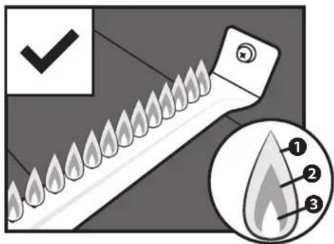
text_image
Diagram illustrating a tool with flame-like patterns and labeled parts, including checkmark and droplet shapes.How to Season a New Blackstone Griddle | Blackstone Griddle

text_image
BLACKSTONE CHEF NATHAN LIPPY 001/5/26youtube.com/
watch?v=VspmDVnj2pl&t=3s

natural_image
Three simple line drawings: a pair of tongs, a rolled document, and a droplet (no text or symbols)natural_image
Hand cleaning a dark surface with a cloth (no text or symbols visible)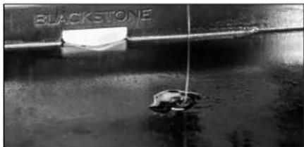
text_image
BLACKSTONE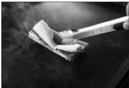
natural_image
Close-up of a hand using a spatula to clean or smok wood on a dark surface (no text or symbols visible)
natural_image
Close-up of a textured surface with indistinct dark and light patches, possibly a material or material sample (no visible text or symbols)POURQUOI DOIS-JE ASSAISONNER MA PLAQUE CHAUFFANTE?
natural_image
Close-up of a dark, glossy metal container or tank with no visible text or symbolsMISE EN GARDE
CAUSES POSSIBLES SOLUTION
CAUSES POSSIBLES SOLUTION
natural_image
Blackstone griddle seasoning jar with a spoon, placed on a surface next to a lid (no visible text or symbols on the jar itself)natural_image
Close-up of a hand using a black Clothes Dryer (no visible text or symbols)Section 04
NETTOYER LE DESSUS DE VOTRE PLAQUE CHAUFFANTE
natural_image
Close-up of a hand using a power tool to cut metal sheets (no text or symbols visible)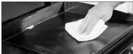
natural_image
Hand cleaning a metal tray with a cloth (no text or symbols visible)
natural_image
Hand pouring liquid into a black table with visible bubbles and contents (no text or symbols)
natural_image
Hand cleaning a surface with a cloth (no text or symbols visible)
natural_image
Close-up of a hand using a tool to apply material or equipment on a metal tray (no visible text or symbols)PREMIER NETTOYAGE
Recovering your Blackstone Griddle Top

natural_image
Hand pressing a black rectangular object on a dark surface, no visible text or symbolsyoutube.com/
watch?v=thPE2IgnSil

ATTENTION
natural_image
Technical line drawing of a mechanical bracket with mounting holes and a handle (no text or symbols)natural_image
Technical line drawings of a mechanical assembly with mounting brackets and internal components (no text or symbols)natural_image
Technical line drawing of a mechanical assembly with no visible text or symbolsnatural_image
Isometric line drawing of a rectangular container with internal mesh structure and mounting points (no text or symbols)ALLUMAGE | FRITEUSE À AIR
FONCTIONNEMENT DE LA FRITEUSE À AIR PROPANE
text_image
1 BLACKSTONE 3 HIGH MED LOW 4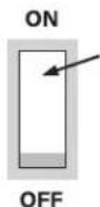
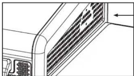
natural_image
Technical line drawing of a mechanical component with internal grid pattern (no text or symbols)text_image
Technical diagram showing a circular component with labeled parts and a magnified cross-section of the 'BLACKSTONE' component.DÉPANNAGE
CAUSES POSSIBLES SOLUTION
CAUSES POSSIBLES SOLUTION
natural_image
Illustration of a fire extinguisher with flame and valve mechanism (no text or symbols)SYMPTÔMES
CAUSES POSSIBLES SOLUTION
text_image
Safety warning sign with pictogram of a fire extinguisher and prohibition symbolSYMPTÔMES
CAUSES POSSIBLES SOLUTION
youtube.com/blackstonegriddles

SYMPTÔMES
CAUSES POSSIBLES SOLUTION
text_image
Diagram showing a tool with flame-like patterns and an inset highlighting three labeled parts (1, 2, 3) with checkmark indicators.natural_image
Sketch of a hamburger with visible bun, scallions, and toppings (no text or symbols)RECETTES POUR LE DÉJEUNER ET LE DÎNER
BURGER À L'OIGNON FRIT OKLAHOMA
Pour 4 | 7 minutes
Ingrédients
blackstoneproducts.com/blogs/recipes

youtube.com/c/ BlackstoneGriddles


@blackstoneproducts
RECETTES POUR LE PETIT DÉJEUNER
natural_image
Sketch of layered dessert with strawberries and toppings (no text or symbols)Pour 6 | ⏻ 45 minutes
Ingrédients Crêpes
blackstoneproducts.com/blogs/recipes

youtube.com/c/ BlackstoneGriddles


@blackstoneproducts

natural_image
Sketch of sliced lettuce showing whole and cross-section (no text or symbols)RECETTES POUR LE DÉJEUNER ET LE DÎNER
TACOS IVRES
blackstoneproducts.com/blogs/recipes

youtube.com/c/ BlackstoneGriddles


@blackstoneproducts
GARANTIE D'UN AN DE NORTH ATLANTIC IMPORTS LLC
text_image
BLACKSTONE BLACKSTONE165^ For 74^ C
160^ For 71^ C
160^ For 71^ C
natural_image
Line drawings of two types of wrenches: a standard screwdriver and an adjustable wrench (no text or symbols present)
natural_image
Line drawing of a cylindrical battery with a separate 2.5A batteries shown in opposite directions (no text or symbols)natural_image
Technical line drawing of a rectangular frame with four circular components attached (no text or symbols)natural_image
Technical line drawing of a mechanical cart with wheels and structural supports (no text or symbols)natural_image
Technical line drawing of a mechanical cart with wheels and support legs (no text or symbols)natural_image
Technical line drawing of a rectangular frame with vertical supports and mounting holes, no text or symbols presentnatural_image
Technical line drawing of a mechanical frame with vertical supports and mounting holes (no text or symbols)natural_image
Technical line drawing of a mechanical cart with wheels and a side panel (no text or symbols)natural_image
Technical line drawing of a server rack with labeled components and mounting hardware (no readable text or symbols)natural_image
Line drawing of a multi-wheeled industrial machine with wheels and ventilation grilles (no text or symbols)natural_image
Technical illustration of a mechanical device with a magnified inset showing a moving cart on a surface (no text or symbols present)natural_image
Technical line drawing of a mechanical device with an inset close-up showing internal components (no text or symbols)natural_image
Pure diagram of a rectangular panel with two curved arrows and circular components, no text or symbols present.text_image
BLACKSTONE ① ②natural_image
Pure diagram of a rectangular frame with vertical supports and arrows, no text or symbols presentnatural_image
Technical line drawing of a rectangular device with internal components and a curved handle (no text or symbols)text_image
BLACKSTONE BLACKSTONE
natural_image
Technical line drawing of a mechanical component with a curved arrow indicating direction (no text or symbols)text_image
Technical diagram of a blackstone industrial machine with labeled components and close-up insets showing internal wiring connections.natural_image
Technical line drawing of a mechanical device with an inset close-up showing internal components (no text or symbols)natural_image
Technical line drawing of a mechanical device with three circular insets showing close-ups of components (no text or symbols)natural_image
Technical line drawing of a mechanical component with mounting brackets and a circular emblem (no text or symbols)ADVERTENCIA
text_image
Technical diagram of a blackston industrial device with labeled ports and mounting brackets, showing front and side views with annotations.natural_image
Technical line drawing of a mechanical support structure with mounting holes and roller handles (no text or symbols)natural_image
Technical line drawing of a metal bracket with mounting holes and a curved top surface (no text or symbols)PRECAUCIÓN
text_image
Technical diagram showing two views (A and B) of a device with labeled components and directional arrows indicating assembly or assembly.
natural_image
Technical line drawing of a mechanical clamp or bracket assembly with mounting holes and a diagonal cross-section (no text or symbols)natural_image
Technical line drawings of two electronic device components: a box with internal structure and a mounted bracket (no text or symbols)text_image
BLACKSTONE BLACKSTONEnatural_image
Line drawing of a blackstone gas stove with control knobs and fan (no text or symbols)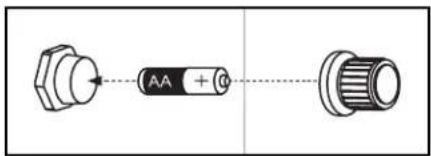
text_image
AA + 0natural_image
Technical diagram showing a mechanical assembly with a magnified inset of a pipe fitting detail (no text or symbols present)natural_image
Technical line drawing of a mechanical assembly with a tool inserted, showing no text or symbolsnatural_image
Diagram of a server rack with two circular insets showing binoculars (no text or symbols)natural_image
Technical line drawing of a mechanical assembly inside a circular frame (no text or symbols)natural_image
Line drawing of a black stone gas stove with control panel and wheels (no text or symbols)natural_image
Sketch of three eggplant slices showing different shapes and textures (no text or symbols)Para 4 - 6 | Ⓞ 50 minutos
Ingredientes
blackstoneproducts.com/blogs/recipes

youtube.com/c/BlackstoneGriddles


@blackstoneproducts
⚠️ PELIGRO
text_image
Technical diagram showing mechanical assembly with labeled components and motion arrows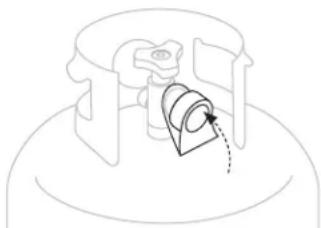
natural_image
Pure mechanical component diagram without any text, numbers, or symbolsLLENADO E INTERCAMBIO
blackstoneproducts.com/support
text_image
QR code image containing encoded data, no visible human-readable textADVERTENCIA
natural_image
Architectural floor plan showing room layouts and structural elements (no text or labels)Sección 02
LIMPIEZA DEL CONJUNTO DEL QUEMADOR
natural_image
Close-up of a hand adjusting metal brackets on a dark surface (no text or symbols visible)natural_image
Close-up of a hand holding a screwdriver tip, no visible text or symbolsnatural_image
Close-up of hands using a tool to adjust or trim a metal object (no visible text or symbols)VIDEO TUTORIAL
How to Clean Your Burner Tube | Blackstone Griddle
text_image
Scanned screenshot of a media player interface showing a hand holding a device with buttons and text instructions in Chinese.natural_image
Close-up of hands holding a metal tool with a small wire, no visible text or symbolsyoutube.com/ watch?v=xKQTCrFCzf8

text_image
Safety warning sign with pictogram of a fire extinguisher and no symbol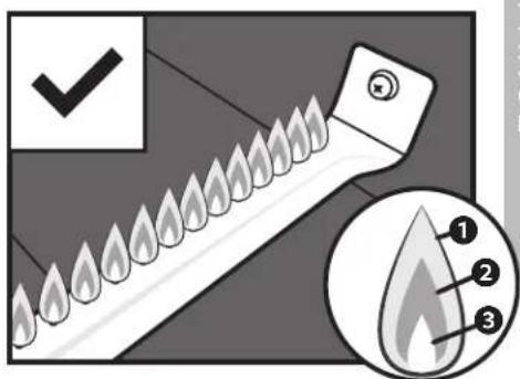
text_image
Diagram illustrating a flame detection mechanism with labeled parts and checkmark indicatorHow to Season a New Blackstone Griddle | Blackstone Griddle

text_image
BLACKSTONE CHEF NATHAN LIPHY 001/526natural_image
Three simple line drawings: a pair of tongs, a rolled paper sheet, and a droplet (no text or symbols)natural_image
Hand cleaning a dark surface with a cloth (no text or symbols visible)
natural_image
Black stone ship with a small boat floating on water, no visible text or symbols
natural_image
Close-up of a hand using a spatula to clean food on a dark surface, with steam rising in the background (no text or symbols visible)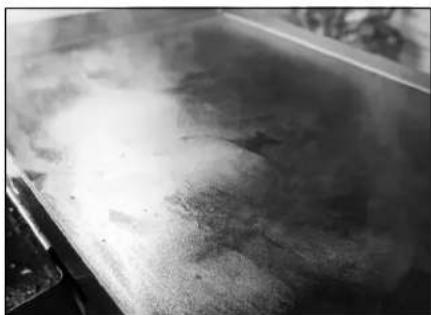
natural_image
Close-up of a textured surface with no visible text or symbolsnatural_image
Close-up of a dark, glossy metal container or tank with a flat lid (no visible text or symbols)PRECAUCIÓN
Seasoning and Cast Iron
natural_image
Black stone jar with a spoon lifting a griddle, next to a dark container (no visible text or symbols)natural_image
Close-up of a hand using a power tool to cut or spread material on a metal tray (no text or symbols visible)
natural_image
Hand cleaning a metal tray with a white cloth (no text or symbols visible)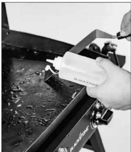
natural_image
Close-up of a hand pouring liquid from a bottle into a black stove (no visible text or symbols)
natural_image
Hand cleaning a metal tray with a cloth (no text or symbols visible)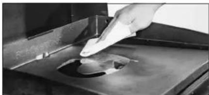
natural_image
Close-up of a hand using a tool to apply material to a metal tray (no visible text or symbols)LA PRIMERA LIMPIEZA
Recovering your Blackstone Griddle Top
natural_image
Hand pressing a black square button on a dark surface, with no visible text or symbols.youtube.com/
watch?v=thPE2IgnSil

ADVERTENCIA
natural_image
Isometric line drawing of a mechanical bracket with internal components and mounting holes (no text or symbols)natural_image
Technical line drawings of a mechanical assembly with mounting brackets and internal components (no text or symbols)natural_image
Technical line drawing of a mechanical component with no visible text or symbolsnatural_image
Technical line drawing of a rectangular enclosure with internal grid pattern and mounting bracket (no text or symbols)ENCENDIDO | FREIDORA DE AIRE
text_image
1 BLACKSTONE 3 HIGH MED LOW 4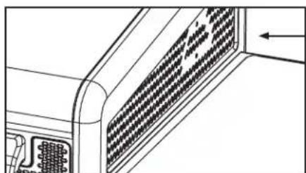
natural_image
Technical line drawing of a computer ventilation grille with no text or symbolstext_image
Technical diagram showing a circular component with labeled parts and a close-up of the internal blackstone component with directional arrows.natural_image
Illustration of a fire extinguisher with flame and valve mechanism (no text or symbols)SÍNTOMAS
text_image
Safety warning sign with pictogram of a fire extinguisher and prohibition symbolSÍNTOMAS
text_image
Diagram illustrating a tool with flame-like patterns and numbered parts, including checkmark and magnified view of the tip.natural_image
Sketch of a hamburger with visible bun, buns, and toppings (no text or symbols)blackstoneproducts.com/blogs/recipes

youtube.com/c/ BlackstoneGriddles


@blackstoneproducts
natural_image
Sketch-style illustration of layered dessert with strawberries and toppings (no text or symbols)Para 6 | 45 minutos
blackstoneproducts.com/blogs/recipes

youtube.com/c/ BlackstoneGriddles


@blackstoneproducts

natural_image
Black-and-white line drawing of sliced lettuce showing whole and cross-section (no text or symbols)blackstoneproducts.com/blogs/recipes

youtube.com/c/ BlackstoneGriddles


@blackstoneproducts