LS4T - Log splitter JCB - Free user manual and instructions
Find the device manual for free LS4T JCB in PDF.


User questions about LS4T JCB
0 question about this device. Answer the ones you know or ask your own.
Ask a new question about this device
Download the instructions for your Log splitter in PDF format for free! Find your manual LS4T - JCB and take your electronic device back in hand. On this page are published all the documents necessary for the use of your device. LS4T by JCB.
USER MANUAL LS4T JCB
natural_image
Technical line drawing of a mechanical device with grid frame and motor (no text or symbols)
JCB-LS4T
EN OPERATING INSTRUCTIONS 8
text_image
Technical diagram of a mechanical device with numbered parts and close-up insets for assembly or maintenance reference.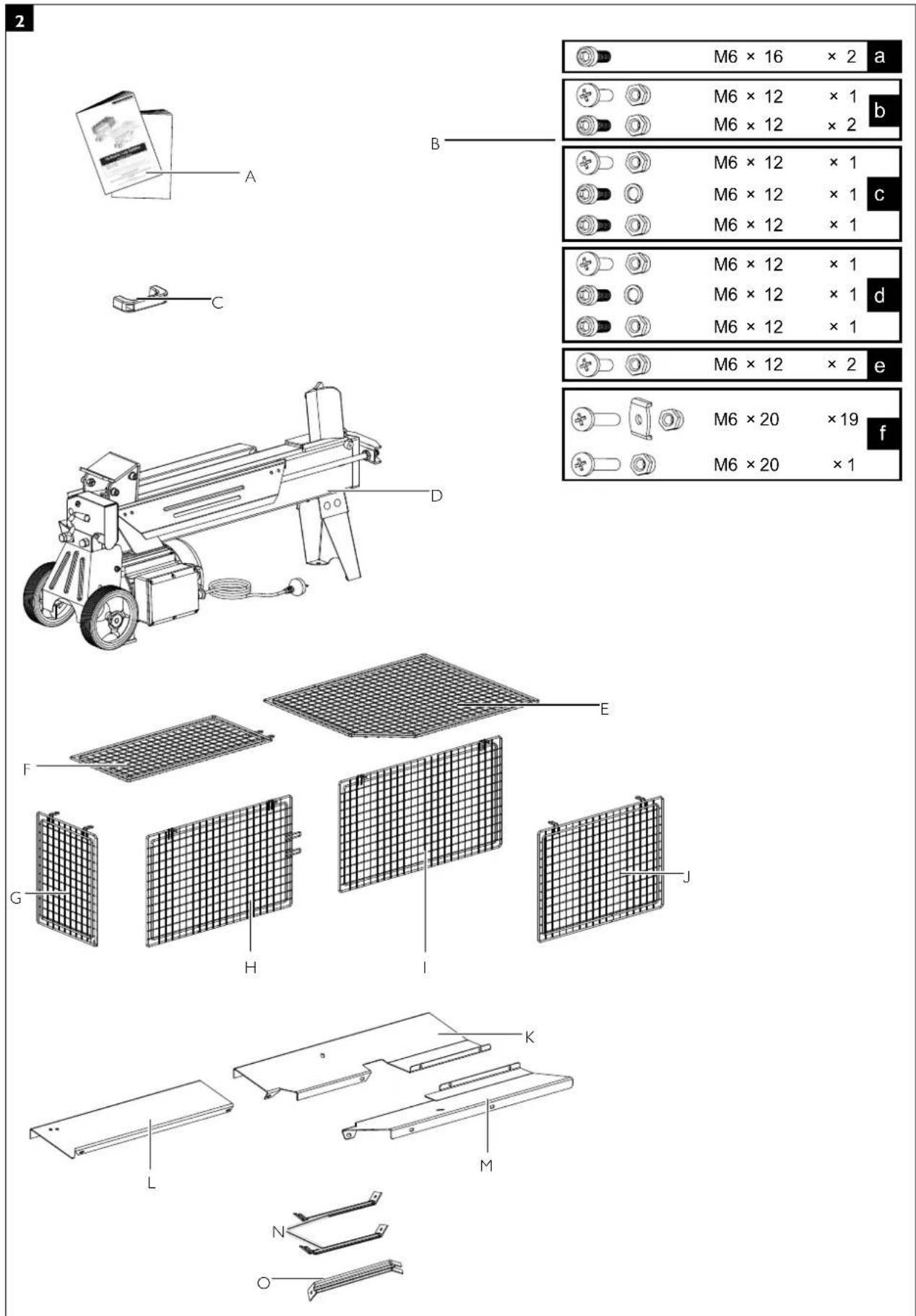
text_image
2 M6 × 16 × 2 a M6 × 12 × 1 b M6 × 12 × 2 c M6 × 12 × 1 d M6 × 12 × 1 e M6 × 12 × 2 f M6 × 20 × 19 f M6 × 20 × 1 A B C D E F G H I J K L M N O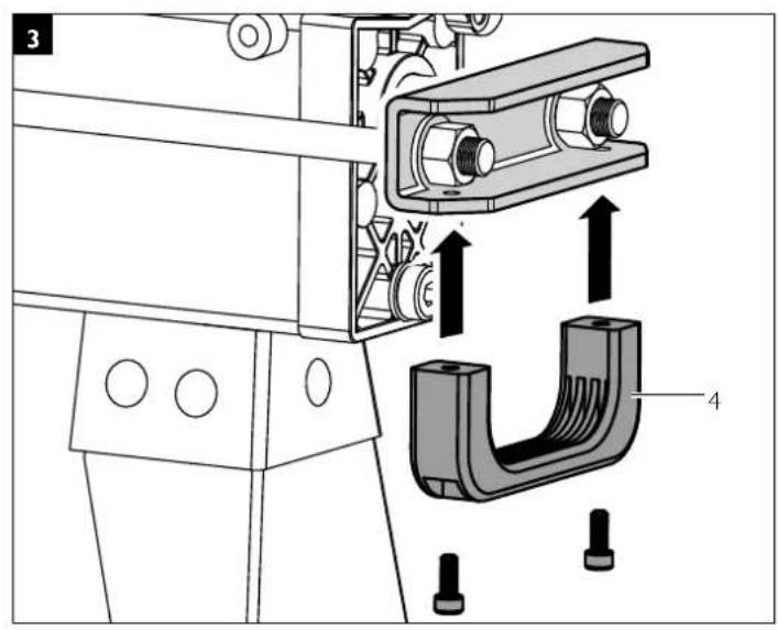
text_image
Technical diagram showing mechanical assembly with labeled parts and directional arrows indicating motion or force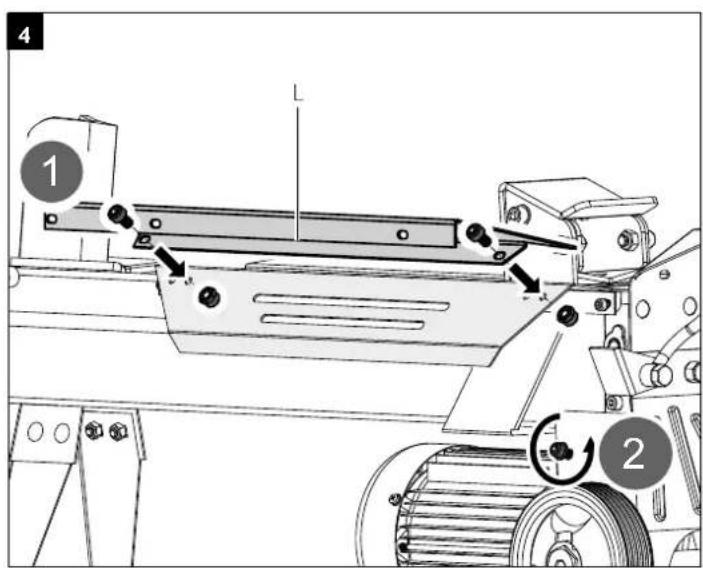
text_image
4 1 2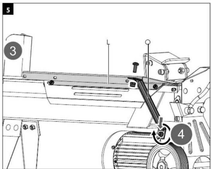
text_image
5 3 4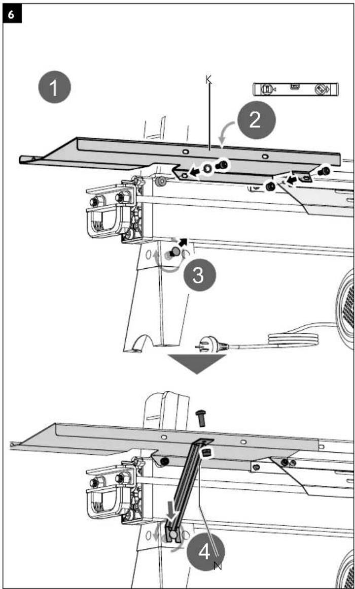
text_image
Technical diagram of a mechanical assembly with numbered components and directional arrows indicating motion or assembly steps.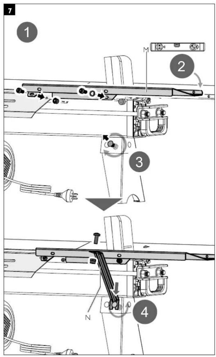
text_image
Technical diagram of a mechanical assembly with numbered components and labeled parts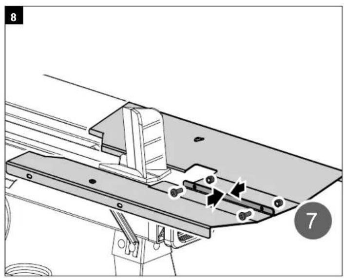
natural_image
Technical diagram of a mechanical assembly with labeled components (no readable text or symbols)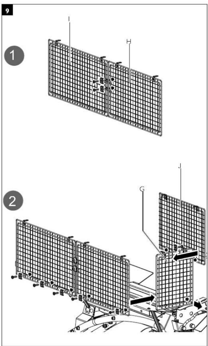
text_image
Technical diagram showing two stages of satellite or radar system installation with labeled components (I, H, G)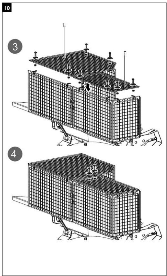
text_image
10 3 E F 4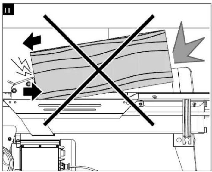
natural_image
Diagram of a machine with a diagonal line crossing through it, showing mechanical components and directional arrows (no text or symbols)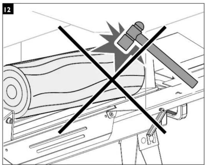
natural_image
Diagram of a mechanical device with a crossed black line and satellite icon, no readable text or symbols present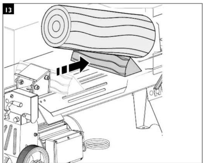
natural_image
Technical line drawing of a machine tool pressing a large cylindrical component, with no visible text or symbols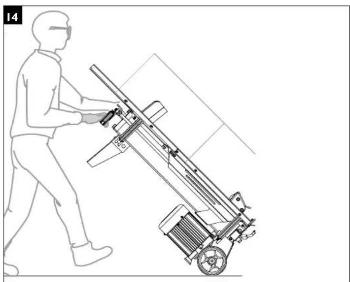
natural_image
Line drawing of a person pushing a mechanical device with a wheel and spring (no text or symbols)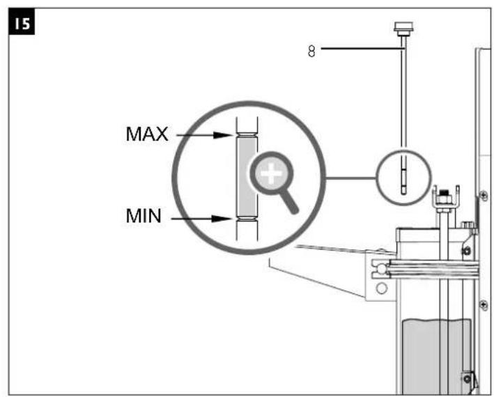
text_image
15 MAX MIN 8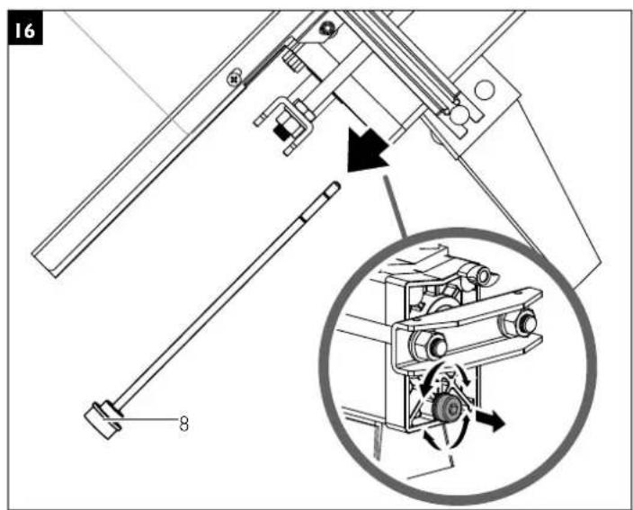
text_image
16 8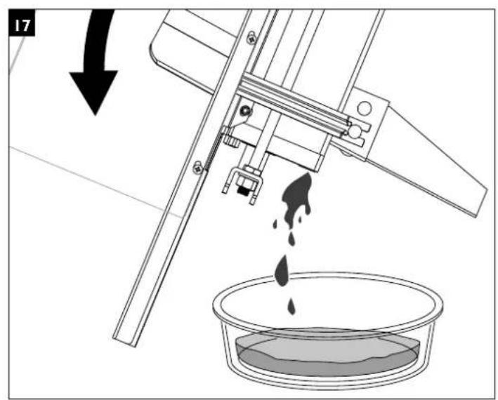
text_image
17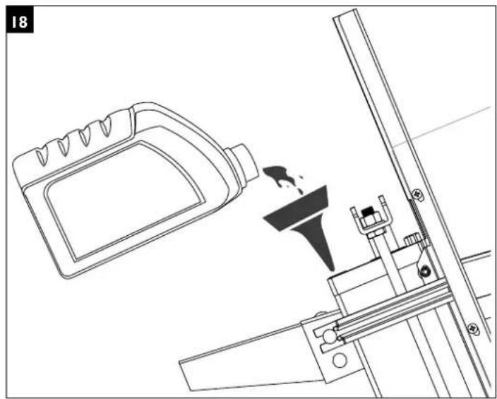
natural_image
Technical line drawing of a mechanical assembly with a bottle and lever mechanism (no text or symbols)Explanation of the symbols on the equipment
The use of symbols in this manual is intended to draw your attention to possible risks. The safety symbols and the explanations that accompany them must be perfectly understood. The warnings in themselves do not remove the risks and cannot replace correct actions for preventing accidents.
 | Please read the manual before start-up |
 | Use hearing protection |
 | Wear safety footwear |
 | Use safety goggles |
 | Wear work gloves |
 | Do not remove or modify protection and safety devices. |
 | Do not spill hydraulic oil on the floorDispose of waste oil correctly (waste oil collection point on site). Do not dump waste oil in the ground or mix it with waste. |
 | Caution! Switch off the motor before repair, maintenance and cleaning. Unplug the mains plug. |
 | High-voltage, danger to life! |
 | Do not reach into the rift area!Risk of injury! Risk of cutting and crushing! |
 | Do not reach into the machine without any protection! |
 | Caution! Moving parts! |
 | Only the operator is allowed in the work area of the machine. Keep other people and animals (minimum distance 5 m) at a distance. |
| ⚠ Attention! | In this operating manual, we have used this sign to mark all sections that concern your safety. |
Table of contents: Page:
I. Introduction 10
2. Device description 10
3. Contents 10
4. Intended use 10
5. Safety notes 11
6. Additional safety instructions 12
7. Technical data 12
8. Unpacking 12
9. Assembly / Before starting the equipment 13
10. Initial operation 13
11. Electrical connection 14
12. Cleaning 14
13. Transport 15
14. Storage 15
15. Maintenance 15
16. Disposal and recycling 15
17. Troubleshooting 16
18. Warranty Statement 17
19. EU Declaration of Conformity 18
I. Introduction
Dear customer,
We hope your new tool brings you much enjoyment and success.
Note:
According to the applicable product liability laws, the manufacturer of the device does not assume liability for damages to the product or damages caused by the product that occurs due to:
- Improper handling,
• Non-compliance of the operating instructions,
• Repairs by third parties, not by authorized service technicians,
• Installation and replacement of non-original spare parts,
• Application other than specified, - A breakdown of the electrical system that occurs due to the non-compliance of the electric regulations and VDE regulations 0100, DIN 57113 /VDE0113.
We recommend:
Read through the complete text in the operating instructions before installing and commissioning the device.
The operating instructions are intended to help the user to become familiar with the machine and take advantage of its application possibilities in accordance with the recommendations.
The operating instructions contain important information on how to operate the machine safely, professionally and economically, how to avoid danger, costly repairs, reduce downtimes and how to increase reliability and service life of the machine.
In addition to the safety regulations in the operating instructions, you have to meet the applicable regulations that apply for the operation of the machine in your country.
Keep the operating instructions package with the machine at all times and store it in a plastic cover to protect it from dirt and moisture. Read the instruction manual each time before operating the machine and carefully follow its information. The machine can only be operated by persons who were instructed concerning the operation of the machine and who are informed about the associated dangers. The minimum age requirement must be complied with.
In addition to the safety instructions in this operating manual and the separate regulations of your country, the generally recognised technical rules for operating woodworking machines must also be observed.
We accept no liability for accidents or damage that occur due to a failure to observe this manual and the safety instructions.
2. Device description (Fig I, P2)
- Guard
- Riving knife
- Tray table for split logs
- Handle
- Trunk guide plate
- Start button
- Ventilation screw
7a. Travel limiting ring - Oil drain screw with dipstick
- Support surface
- Pressure plate
II. Control lever protection - Control lever
- Motor
- Transport wheels
- Pressure limiting screw
- Foot
3. Contents
A. Operating manual
B. Enclosed accessories bag (a, b, c, d, e, f)
C. Handle
D. Log splitter
E. Top guard I
F. Top guard 2
G. Left guard
H. Rear guard I
I. Rear guard 2
J. Front guard
K. Tray table I
L. Protective guard
M. Tray table 2
N. Struts (2x)
O. Strut
4. Intended use
The equipment is to be used only for its prescribed purpose. Any other use is deemed to be a case of misuse. The user / operator and not the manufacturer will be liable for any damage or injuries of any kind caused as a result of this.
To use the equipment properly you must also observe the safety information, the assembly instructions and the operating instructions to be found in this manual.
All persons who use and service the equipment have to be acquainted with this manual and must be informed about the equipment's potential hazards.
It is also imperative to observe the accident prevention regulations in force in your area. The same applies for the general rules of health and safety at work.
The manufacturer will not be liable for any changes made to the equipment nor for any damage resulting from such changes.
- The hydraulic log splitter is only suitable for horizontal operation. Wood may only be split while horizontal and in the direction of the grain. Dimensions of wood to be split: maximum length 370mm & 250mm ø.
- Never split wood against the grain or while in an upright position.
- The manufacturer's safety, operation and maintenance instructions as well as the technical data given in the calibrations and dimensions must be adhered to.
- Relevant accident prevention regulations and other generally recognized safety and technical rules must also be adhered to.
- The machine may only be used, maintained or repaired by trained persons who are familiar with the machine and have been informed about the dangers. Unauthorized modifications of the machine exclude a liability of the manufacturer for damages resulting from the modifications.
- Any other use is considered to be not intended. The manufacturer excludes any liability for resulting damages, the risk is exclusively borne by the user.
- Keep work area clean and free of obstacles.
- Operate the unit only on a flat and firm surface.
- Check the proper function of the splitter before each start-up.
- Operate only in areas no greater than a maximum altitude of 1000m above sea level.
5. Safety notes
⚠ WARNING: When you use electric machines, always observe the following safety instructions in order to reduce the risk of fire, electric shock, and injuries.
Please read all the instructions before you work with this machine.
- Observe all safety notes and warnings attached to the machine.
- See to it that safety instructions and warnings attached to the machine are always complete and perfectly legible.
- Protection and safety devices on the machine may not be removed or made redundant.
- Check electrical connection leads. Do not use any faulty connection leads.
- Before putting into operation check the correct function of the two-hand control.
- Operating personnel must be at least 18 years of age. Trainees must be at least 16 years of age, but may only operate the machine under adult supervision.
• Children may not work with this device - Wear safety gloves, safety goggles, close-fitting work clothes, and hearing protection (PPE) while working.
- Caution when working: There is a danger to fingers and hands from the splitting tool.
- Before starting, setting, cleaning, maintenance or repair work, always switch off the machine and disconnect the plug from the power supply.
- Connections, repairs, or servicing work on the electrical equipment may only be carried out by an electrician.
- All protection and safety devices must be replaced after completing repair and maintenance procedures.
- When leaving the work place, switch off the machine and disconnect the plug from the power supply.
- Removing or working without guards is prohibited.
- When splitting, the properties of the wood (e.g. growths, trunk slices of irregular shape, etc.) can result in hazards such as ejecting parts, splitter blocking, and crushing.
6. Additional safety instructions
• The log splitter may only be operated by one person.
- Never split logs containing nails, wire, or other foreign objects.
- Already split wood and wood chips can be dangerous. You can stumble, slip or fall down. Keep the working area tidy.
- While the machine is switched on, never put your hands on moving parts of the machine.
- Only split logs with a maximum length of 37 cm.
⚠ WARNING! This electric tool generates an electromagnetic field during operation. This field can impair active or passive medical implants under certain conditions. In order to prevent the risk of serious or deadly injuries, we recommend that persons with medical implants consult with their physician and the manufacturer of the medical implant prior to operating the electric tool.
Remaining hazards
The machine has been built using modern technology in accordance with recognized safety rules. Some remaining hazards, however, may still exist.
- The splitting tool can cause injuries to fingers and hands if the wood is incorrectly guided or supported.
- Thrown pieces can lead to injury if the work piece is not correctly placed or held.
- Injury through electric current if incorrect electric connection leads are used.
- Remaining hazards can be minimized by following the safety instructions as well as the instructions in the chapter Authorized use and in the entire operating manual.
• Health hazard due to electrical power, with the use of improper electrical connection cables. - Release the handle button and switch off the machine prior to any operations.
- Avoid accidental starts of the machine: Do not press the start button while inserting the plug into the socket.
- Use the tools recommended in this manual to obtain the best results from your machine.
• Always keep hands away from the work area when the machine is running.
7. Technical data
| Dimensions L x W x H 995 x 425 x 610 mm | |
| Wood ø max 25 cm | |
| Wood length max 37 cm | |
| Weight 45 kg | |
| Motor 230 V~/50 Hz | |
| Input P1 1500 W | |
| Output P2 1100 W | |
| JEC Duty Rating SI | |
| Splitting Power | max. 4 t |
| Cylinder rise 290 mm | |
| Cylinder speed (fast fwd.) | 3,86 cm/sec |
| Cylinder speed (return) | 6,44 cm/sec |
| Hydraulic fluid capacity | 2,4 l |
| Operating pressure | 165 Bar / 16.5 MPa |
| Motor speed 2850 l/min | |
| Max load current | 6 A |
Subject to technical changes!
Noise
⚠ WARNING: Noise can have serious effects on your health. If the machine noise exceeds 85 dB (A), please wear suitable hearing protection.
8. Unpacking
- Open the packaging and remove the device carefully.
- Remove the packaging material as well as the packaging and transport bracing (if available).
- Check that the delivery is complete.
- Check the device and accessory parts for transport damage.
• In case of complaints the dealer must be informed immediately. Subsequent complaints will not be accepted. - If possible, store the packaging until the warranty period has expired.
- Read the operating manual to make yourself familiar with the device prior to using it.
- Only use original parts. Spare parts are available from your specialized dealer.
- Specify our part numbers as well as the type and year of construction of the device in your orders.
ATTENTION
The device and packaging materials are not toys! Children must not be allowed to play with plastic bags, film and small parts! There is a risk of swallowing and suffocation!
9. Assembly / Before starting the equipment
At least two people are required to assemble the device.
9.1 Installing the handle (4 Fig.1) (enclosed accessories bag a) (fig. 3)
Fasten the handle to the U-bar with the two M6 x 16 screws.
9.2 Installing the protective guard (L Fig.2) (enclosed accessories bag b) (fig. 4 + 5)
- Fit the protective guard (L) to the trunk guide plate (5 Fig.1) and use the enclosed socket head screws and nuts to affix it.
- Undo the socket head screw and washer that is located on the wheel bracket.
- Fasten the other end of the strut to the protective guard using the Phillips head screw and nut. (3)
- Now guide the open end of the strut (O Fig.2) between the washer and the wheel bracket, tighten the socket head screw (4) again firmly.
9.4 Installing the tray table (K, M Fig.2) (enclosed accessories bag c + d + e) (fig. 6 + 7 + 8)
- Attach the tray table (K) to the same side as the protective guard (L). Use two socket head screws and spring washers to affix the table to the log splitter. (I)
- Ensure that the table and the protective guard are level in relation to each other.
- Undo the screw on the left of the foot.
- Fasten the other end of the strut to the protective guard using the Phillips head screw and nut, align everything and tighten the screw firmly.
- Now guide the open end of the strut (N) between the screw and the foot bracket, tighten the screw slightly.
- Repeat the process on the other side.
- Align both tables in relation to each other and use the Phillips head screws and nuts (e) to affix them.
9.5 Installing the guard (E, J Fig.2) (enclosed accessories bag f) (fig. 9 + 10)
I. Connect the guards (H, I Fig.2) together, using two Phillips head screws, clamping brackets and nuts.
2. Fasten the guards (H, I, J) to the holes provided on the table. These are on the side of the table and the protective guard. Fasten the guards with seven Phillips head screws, clamping brackets and nuts. Fit the protective guard (G Fig.2) to the control lever protection bracket (II Fig.2) and use a Phillips head screw and a nut to affix it.
3. Now fasten the guards (E, F Fig.2) on the top. Fasten them with eight Phillips head screws, clamping brackets and nuts.
4. Fasten the guards (E + F) together using two Phillips head screws, clamping brackets and nuts.
⚠️ IMPORTANT!
You must fully assemble the appliance before using it for the first time!
10. Initial operation
Before start-up, place the splitter on a stable, level and flat surface so that the splitter tray table sits at a height of 72 - 85 cm.
Make sure the machine is completely and expertly assembled. Check before every use:
- the connection cables for any defective issues (cracks, cuts etc.).
• the machine for any possible damage. - all bolts are fully tightened.
• the hydraulic system for leakage. - the oil level
- the safety devices
10.1 Checking the oil level (Fig. 15)
The hydraulic unit is a closed system with oil tank, oil pump and control valve. Check the oil level regularly before every use. Too low an oil level can damage the oil pump. If the oil level is at the lower notch, then the oil level is at a minimum. Should this be the case, oil must be immediately added. The upper notch indicates the maximum oil level. The machine must be on level ground. Screw in the oil dipstick fully, to measure the oil level.
10.2 Ventilation screw
Before operating your machine, the bleed screw (7 Fig.1) should be loosened by a few rotations until air can go in and out of the oil tank smoothly. Failure to loosen the bleed screw will keep the sealed air in the hydraulic system being continually compressed and decompressed. Such continuous compression/decompression will blow out the seals of the hydraulic system and cause permanent damage to your machine. Before moving your machine, make sure the bleed screw is tightened to avoid oil leaking from this point.
10.3 Splitting logs
Only split logs that have been sawn off straight. To do this, proceed as follows:
I. Place the log onto the work table (9 Fig. I).
2. Your machine is equipped with a Two-hands Control System that requires operation by both hands of the user – left hand controls the control lever (12 Fig.1) while right hand controls the push button start switch (6 Fig.1).
3. Simultaneously operate the push button start switch (6) and central lever (12) to start the splitting action.
The log splitter will freeze upon removal of either hand from the start switch or control lever.
Never force your machine for more than 5 seconds by keeping pressure on it to split excessively hard wood.
After this time interval, the oil under pressure will be overheated and the machine could be damaged. For such
extremely hard log, rotate it by 90^ to see whether it can be split in a different direction. In any case, if you are not able to split the log, this means that its hardness exceeds the capacity of the machine and thus should be discarded to protect the log splitter.
10.4 Travel limiting
It is reasonable to limit the hoist of the pressure plate (10 Fig. 1) for short splitting material. Thereto press the control lever (12) and the release button (6) and let the pressure plate (10) move just in front of the splitting material.
Release the release button now and mount the travel limiting ring (7a Fig.1)) to the housing and tighten it. Afterwards you can release the hydraulics lever.
The pressure plate will now be resting in the selected position.
10.5 Wrongly placed log (Fig. 11)
Always set logs firmly on the log retaining plates and work table. Make sure logs will not twist, rock or slip while being split. Do not force the blade by splitting logs on the upper part. This will break the blade or damage the machine.
Do not attempt to split two pieces of logs at the same time.
One of them may fly up and cause serious personal injury.
10.6 Jammed log (Fig. 12 + 13)
Do not try to knock the jammed log off. Knocking about will damage the machine or may displace the log and cause an accident.
I. Release both controls.
2. After the log pusher moves back and completely stops at its starting position, insert a wooden wedge under the jammed log (see figure 13).
3. Start the log splitter to push the wooden wedge under the jammed one.
4. Repeat the above procedure with sharper sloped wooden wedges until the log is completely freed.
II. Electrical connection
The electrical motor installed is connected and ready for operation. The connection complies with the applicable VDE and DIN provisions.
The customer's mains connection as well as the extension cable used must also comply with these regulations.
Damaged electrical connection cable
The insulation on electrical connection cables is often damaged.
This may have the following causes:
• Passage points, where connection cables are passed through windows or doors.
- Kinks where the connection cable has been improperly fastened or routed.
- Places where the connection cables have been cut due to being driven over.
• Insulation damage due to being ripped out of the wall outlet.
• Cracks due to the insulation ageing.
Such damaged electrical connection cables must not be used and are life-threatening due to the insulation damage.
Check the electrical connection cables for damage regularly. Make sure that the connection cable does not hang on the power network during the inspection.
Electrical connection cables must comply with the applicable VDE and DIN provisions. Only use connection cables with the marking 'H07RN-F'.
The printing of the type designation on the connection cable is mandatory.
AC motor 230 V/ 50 Hz
Mains voltage 230 Volt / 50 Hz.
- The mains connection and the extension cable have to be three-core cables (Phase, Neurtal, Protective Earth).
- Extension cables must have a minimum cross-section of 1.5 mm^2 .
- Mains fuse protection is 16 A maximum.
12. Cleaning
ATTENTION!
Pull out the power plug before carrying out any cleaning work on the equipment.
We recommend that you clean the equipment immediately after you use it.
Clean the equipment regularly with a damp cloth and some soft soap. Do not use cleaning agents or solvents; these may be aggressive to the plastic parts in the equipment. Ensure that no water can get into the interior of the equipment.
13. Transport
The log splitter is equipped with two wheels for easy transport.
The machine can be transported on the wheels at an angle.
Use the transport handle, lift and pull or push. (Fig. 14)
14. Storage
Store the device and its accessories in a dark, dry and frost-proof place that is inaccessible to children. The optimum storage temperature is between 5 and 30°C.
Cover the electrical tool in order to protect it from dust and moisture.
Store the operating manual with the log splitter.
15. Maintenance
ATTENTION!
Pull out the power plug before carrying out any maintenance work on the equipment.
We recommend:
- The splitting wedge is a wearing part that needs to be sharpened or replaced after wear.
- The combined gripping and controlling device must remain smooth running. Lubricate with a few drops of oil when necessary.
- Keep the splitting wedge drive clean of dirt, wood shavings, bark, etc.
- Lubricate slide rails with grease.
When must the oil be changed?
Change the oil after 150 working hours.
Oil change (Fig. 15 - 18)
- Move the log splitter into the start position and pull out the mains plug.
- Undo the oil drain screw with dipstick (8) and put it to one side. (Fig. 16)
- Turn the log splitter on the support leg side (as shown in fig. 17) over a 4 litre capacity container to drain the hydraulic oil off. Recycle carefully! Dispose of the waste oil in an environmentally friendly manner!
- Turn your machine on the motor side as shown in Fig. 18 to refill about 2,4 l fresh oil.
- Clean the oil drain screw with dipstick (8) and screw it back in to the machine that is still in a vertical position. Unscrew it again; there should be an oil film between the two notches. (Fig. 15)
-
Now screw the oil drain screw with dipstick back in tightly. Afterwards start splitting (without actually splitting a log) several times.
-
Check the oil level one last time and top up with oil if required.
Dispose of the used oil in a correct manner at a public collection facility. It is prohibited to drop old oil on the ground or to mix it with waste.
We recommend oil from the HLP 32 range.
Connections and repairs
Connections and repairs of electrical equipment may only be carried out by an electrician.
Please provide the following information in the event of any enquiries:
• Type of current for the motor
- Machine data - type plate
Service information
Please note that the following parts of this product are subject to normal or natural wear and that the following parts are therefore also required for use as consumables.
Wear parts*: splitting wedge guides, hydraulic oil, splitting wedge.
* Not necessarily included in the scope of delivery!
16. Disposal and recycling
The equipment is supplied in packaging to prevent it from being damaged in transit. The raw materials in this packaging can be reused or recycled. The equipment and its accessories are made of various types of material, such as metal and plastic.
Defective components must be disposed of as special waste.
Ask your dealer or your local council.
Old devices must not be disposed of with household waste!

This symbol indicates that this product must not be disposed of together with domestic waste in compliance with the Directive (2012/19/EU) pertaining to waste electrical and electronic equipment (WEEE). This product must be disposed of at a designated collection point. This can occur, for example, by handing it in at an authorised collecting point for the recycling of waste electrical and electronic equipment. Improper handling of waste equipment may have negative consequences for the environment and human health due to potentially hazardous substances that are often contained in electrical and electronic equipment. By properly disposing of this product, you are also contributing to the effective use of natural resources.
You can obtain information on collection points for waste equipment from your municipal administration, public waste disposal authority, an authorised body for the disposal of waste electrical and electronic equipment or your waste disposal company.
17. Troubleshooting
The table below contains a list of error symptoms and explains what you can do to solve the problem if your tool fails to work properly. If the problem persists after working through the list, please contact your nearest service workshop.
| Problem Possible Cause Remedy | ||
| Motor does not turn. | Overload protection device disengaged to protect the log splitter from being damaged. | Contact a qualified Electrician. |
| Fails to split logs. | Log is improperly positioned. Refer to "operation" section to perfect log loading. | |
| Size of log exceeds the capacity of the machine. | Reduce log size before operating. | |
| Wedge cutting edge is blunt. Sharpen cutting edge. | ||
| Oil leaks. Locate leak(s) and contact your dealer. | ||
| Log pusher moves jerkily, making unfamiliar noise or vibrating a lot. | Lack of hydraulic oil and excessive air in the hydraulic system. | Check oil level for possible refilling. Contact your dealer. |
| Oil leaks around the cylinder ram or ffrom other points. | Air sealed in hydraulic system while operating. | Loosen bleed screw by a few rotations before operating the log splitter. |
| Bleed screw is not tightened before moving the log splitter. | Tighten bleed screw up before moving the log splitter. | |
| Oil drain screw loose. Tighten the oil drain screw firmly. | ||
| Hydraulic control valve assembly and/or seal(s) wom. | Contact your dealer. | |
WARRANTY STATEMENT
JCB Power Tools are guaranteed against manufacturing defects for up to 3 years from date of purchase. Proof of purchase required. This does not affect your statutory rights.
The original sales receipt will be required in the event of any claim within the warranty period.
Warranty cover commences from the date of purchase on the retail sales receipt and is valid only for JCB Tools products bearing the CE mark and a visible serial number.
In the unlikely event your JCB Power Tool is subject to a manufacturing fault within the warranty period, please contact the seller/retailer where the item was purchased.
The above repair or replacement of products will be undertaken providing that:
The product has been subject to fair wear and tear only.
The product has not been subject to accidental or cosmetic damage.
The product has not been misused and has been used only in accordance with the instruction manual provided.
The product has not been subject to overload or insufficient servicing and maintenance.
The product has not been subject to any abnormal environmental conditions or inappropriate operating conditions.
Repairs have not been attempted by an unauthorised person and no modifications have been made to the product.
Repairs have not been undertaken using non-genuine spare parts.
JCB Power Tools used for Hire Fleets or as part of B2B and Service Contracts are not covered by these terms and conditions.
JCB Tools Warranties excludes the following (where relevant):
Components normally subject to wear such as carbon brushes.
Batteries, Chucks and Chargers.
Accessories and consumable items.
Cases and tool storage products.
If your product develops a fault, contact the seller/retailer where it was purchased together with your sales receipt.
Delivery and repair charges may apply at our discretion should the warranty claim be invalid for any of the reasons illustrated above. In the event charges are not accepted the product will be retained by JCB Tools and remain the property of JCB Tools.
Only products purchased from JCB Tools authorised sellers are covered by the warranty.
JCB TOOLS WILL NOT BE LIABLE FOR ANY INJURIES OR CONSEQUENTIAL DAMAGES RESULTING FROM USE OF THIS PRODUCT.
EU DECLARATION OF CONFORMITY
We,
JCB Tools
Declare that the product:
Description
Hydraulic Log Splitter
Type
JCB-LS4T
Function
Log Splitting
Complies with the following Directives;
EC Machinery Directive
2006/42/EC
EC Electromagnetic Compatibility Directive
2014/30/EU
RoHS Directive
2011/65/EU
Standards conform to
EN 60204-1:2006+AI+AC
EN 609-1:2017
EN 55014-1:2017
EN 55014-2:2015
EN 61000-3-2:2014
EN 61000-3-11:2000
The person authorized to compile the technical file:
Date: 20/09/2018
Signature:
T.Bryoge
Name/ title: Tim Burgoyne / Quality Assurance Manager
Address: JCB Tools, 55 Romsey Industrial Estate, Romsey, SO51 0HR, UK.
Company REG: 11062222
CE
Günzburger Straße 69
D-89335 Ichenhausen
Verehrter Kunde
Günzburger Straße 69
D-89335 Ichenhausen
Cher client,
DÉCLARATION DE CONFORMITÉ CE
Nous,
JCB Tools
Directive machines CE
2006/42/CE
Günzburger Straße 69
D-89335 Ichenhausen