2202 - Measuring equipment BGS technic - Free user manual and instructions
Find the device manual for free 2202 BGS technic in PDF.


User questions about 2202 BGS technic
0 question about this device. Answer the ones you know or ask your own.
Ask a new question about this device
Download the instructions for your Measuring equipment in PDF format for free! Find your manual 2202 - BGS technic and take your electronic device back in hand. On this page are published all the documents necessary for the use of your device. 2202 by BGS technic.
USER MANUAL 2202 BGS technic
natural_image
Digital multimeter with red and black wires connected to a blue clamp, no visible text or symbols on the device itself.SPEZIFIKATIONEN
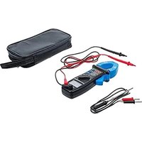
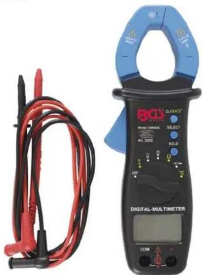
Digital Multimeter with Clamp for DC and AC Current
natural_image
Digital multimeter with red and black wires connected to a BQX 2000 clamp meter (no visible text or symbols on main components)SPECIFICATIONS
Display: 3 3/4-digit LCD, max. reading 3999 Negative Polarity Indication: (−) shown on display Over range Indication: (OL) shown on the display Jaw Opening Capability: 33 mm Max. Measurable Conductor: ∅ 28 mm Battery: 1.5V, AAA or equivalent, two pieces Low Battery Indication: (■) shown on the display Operation Environment: 0° - 40°C, <75%RH Storage Environment: -10°C - 50°C, <85%RH Size: 194 x 71 x 38 mm Weight: about 215g (incl. batteries)
Accuracy is specified for a period of one year after calibration and at 23^ C ±5^ C, with relative humidity up to 76%. Except where specified specially, accuracy is specified from 8 % to 100% of range. Accuracy specifications take the form of:
± ([% of Reading]+[number of Least Significant Digits])
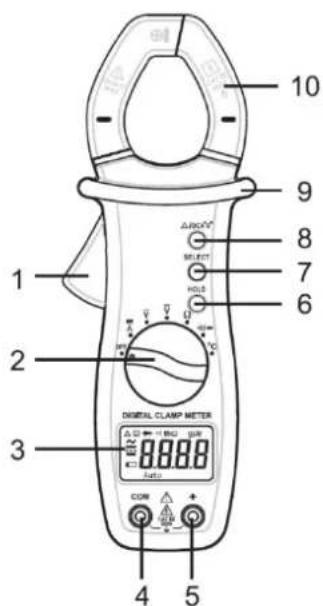
PANEL
1 Trigger is used to open and close the jaws.
2 Function / Range Switch is used to select desired function or range as well as to turn on or off the meter.
3 Display
4 Socket (COM) to connect the black (negative) test lead.
5 Socket (+) to connect the red (positive) test lead.
6 Button (HOLD) is used to enter/exit the data hold mode.switch between auto range mode and manual range mode as well as to select desired manual range.
7 Button (SELECT)
a. When the rotary switch is in the ( ) position, pressing this (SELECT) button to switch the meter between DC current and AC current measurement function.
b. When the rotary switch is in the (•/•) position, pressing this (SELECT) button to switch the meter between diode and continuity test function.
8 Button ( /DCA"0" ) in current measurements, this button can be used for zeroing before measurement. In other measurements, this button can be used to enter or exit relative mode. The (DCA"0") button must be pressed for compensation of measurement error in the 400A range.
9 Tactile Barrier
10 Jaw used for clamping the conductor for current measurements.
text_image
10 9 8 7 6 1 2 3 DIGITAL CLAMP METER ΔDC SELECT HOLD 0.00 0.00 0.00 0.00 0.00 0.00 CON ΔΩ ΔΩ ΔΩ ΔΩ ΔΩ ΔΩ ΔΩ 4 5SAFETY INFORMATIONS
This meter has been designed according to IEC-61010 concerning electronic measuring instrument with a measurement category (CAT III 600V) and pollution degree 2 according to VDE 0110. To avoid possible electric shock or personal injury, follow these guidelines:
- Do not use the meter if it is damaged. Before you use the meter, inspect the case. Pay particular attention to the insulation surrounding the connectors.
- Inspect the test leads for damaged insulation or exposed metal. Check: the test leads for continuity. Replace damaged test lead before you use the meter.
- Do not use the meter if it operates abnormally. Protection may be impaired. When in doubt, have the meter serviced.
- Do not operate the meter around explosive gas, vapour or dusts.
- Do not apply more than the rated voltage, as marked on the meter, between terminals or between any terminal and earth ground.
- Before use, verify the meter's operation by measuring a known voltage.
- When servicing the meter, use only specified replacement parts.
- Use caution when working with voltage above 30V ac rms, 42V peak, or 60V dc. Such voltages pose a shock hazard.
- When using the probes or meter, keep your fingers behind the finger guards on the probes or the meter.
- Connect the common test lead before you connect the live test lead. When you disconnect test leads, disconnect the live test lead first.
- Remove the test leads from the meter and remove the clamp Jaws from the conductor under test before opening the case or the battery cover.
- Do not operate the meter with the battery cover or portions of the case removed or loosened.
- To avoid false readings, which could lead to possible electric shock: or personal injury, replace the batteries as soon as the low battery indicator (☐) appears.
• To avoid electric shock, do not touch any naked conductor with hand or skin. - Do not hold the meter anywhere beyond the tactile barrier.
- Adhere to local and national safety codes. Individual protective equipment must be used to prevent shock and arc blast injury where hazardous live conductors are exposed.
- Remaining endangerment:
When an input terminal is connected to dangerous live potential it is to be noted that this potential at all other terminals can occur!
CAUTION
To avoid possible damage to the meter or to the equipment under test follow these guidelines:
- Disconnect circuit power and discharge all capacitors before testing resistance, diode and continuity.
- Use the proper function and range for your measurements.
- Before rotating the function/range switch to change functions, remove test leads from the circuit under test and remove the jaws from the clamped conductor.
CAUTION
Important information about measurement categories
Use this meter only for measurements of measurement categories I, II and III, never use this meter for measurement category IV measurements.
| CAT I | Measurements on circuits that have no direct connection to the network (battery operation), e.g. Devices of protection class 3 (operation with safety extra-low voltage), battery-operated devices, conventional car electrical system. |
| CAT II | Measurements on circuits that have a direct connection via plug to the low-voltage network, e.g. Household appliances, portable electrical appliances. |
| CAT III | Measurements within the building installation, including stationary consumers with non-pluggable connection, distributor connection, permanently installed devices in the distributor, e.g. Sub-distribution. |
| CAT IV | Measurements at the source of the low voltage installation, including counters, main connection, primary overcurrent protection, e.g. counter, low voltage overhead line, house connection box. |
ELECTRICAL SYMBOLS
| ~ | Alternating Current |
| --- | Direct Current |
| ⚠️ | Caution, risk of danger, refer to the operating manual before use. |
| ⚠️ | Caution, risk of electric shock. |
| ⊥ | Earth (ground) Terminal |
| CE | Conforms to European Union directives |
| ☐ | The equipment is protected throughout by double insulation or reinforced Insulation. |
TECHNICAL DATA
This meter is a 3-3/4 digit auto range digital clamp meter for measuring DC and AC voltage, DC and AC current, resistance, diode and continuity. It is easy to operate and is an ideal measurement tool.
AC Voltage
| Range | Resolution | Accuracy |
| 4.000V | 1mV | ± (1.2%+5) |
| 40.00V | 10mV | ± (1.5%+5) |
| 400.0V | 100mV | |
| 600V | 1V |
Input Impedance: 10 MΩ
Frequency Range: 40Hz - 400Hz
Max. Permitted Input Voltage: 600V rms
Response: Average, calibrated in rms of sine wave
DC Voltage
| Range | Resolution | Accuracy |
| 400.0 mV | 0.1mV | ± (0,8%+5) |
| 4.000V | 1mV | ± (1.0%+5) |
| 40.00V | 10mV | |
| 400.0V | 100mV | |
| 600V | 1V |
Input Impedance: range 400mV: > 100 MΩ, the other ranges: 10MΩ
Max. Permitted Input Voltage: 600V dc
TECHNICAL DATA
Resistance
| Range | Resolution | Accuracy |
| 400.0 Ω | 100 mΩ | ± (1,2%+5) |
| 4.000 KΩ | 1 Ω | ± (1.0%+5) |
| 40.00 KΩ | 10 Ω | |
| 400.0 KΩ | 100 Ω | |
| 4.000 MΩ | 1 KΩ | ± (1.2%+5) |
| 40.00 MΩ | 10 KΩ | ± (1.5%+7) |
Overload Protection: 250V rms
Continuity
| Range | Resolution | Description |
| ●1)) | 0.1 Ω | If the resistance is less than about 30 the buzzer will sound. |
Overload Protection: 250V rms
When the resistance is between 30 Ω and 150 Ω, the buzzer may sound or may not sound.
When the resistance is more than 150 Ω, the buzzer will not sound.
Diode
| Range | Resolution | Description |
| 1 mV | Approx. forward voltage drop of the diode will be displayed.Open Circuit Voltage: about 2.0VTest Current: about 0.6mA |
Overload Protection: 250V rms
AC Current
| Range | Resolution | Accuracy |
| 400 A | 0.1 A | ± (2,5%+5) |
Frequency Range: 50 - 60Hz
Max. Permitted Input Current: 400A
Response: Average, calibrated in rms of sine wave
Temperature Coefficient: 0.1 x (specified accuracy)/°C (<18°C or >28°C)
DC Current
| Range | Resolution | Accuracy |
| 400 A | 0.1 A | ± (2,5%+5) |
Max. Permitted Input Current: 400A
Temperature Coefficient: 1 x (specified accuracy)/C° (<18°C or >28°C)
Temperature
| Range | Resolution | Accuracy |
| -20°C – 0°C | 1°C | ± (4%+5) |
| 0°C – 400°C | ± (1%+5) | |
| 400°C – 1000°C | ± (2%+5) |
Use a K Type Thermocouple
Overload Protection: 250V rms
Note: The accuracy listed above does not include the tolerance of the temperature sensor. Accuracy specification assumes that ambient temperature is stable to ±1^ . For ambient temperature changes of ±5^ , rated accuracy applies after one hour.
-
When you press a button, the buzzer will sound a beep if the press is effective.
-
The buzzer will sound several short beeps about one minute before the meter turns off automatically and will sound a long beep before the meter turns off automatically.
The measuring clamp is equipped with auto range mode, as soon as a measuring category is selected, the auto range mode is active and is indicated by the (Auto) symbol on the display.
Data Hold Mode
In resistance, AC/DC current or AC/DC voltage measurement mode, press the Button (HOLD) to enter the Data Hold mode. The present reading is held on the display, (H) appears on the display as an indicator. To exit the Data Hold mode, just press this button again (H) disappears.
Relative Mode
Selecting Relative mode causes the meter to store the present reading as a reference for subsequent measurements and zero the display.
- Press the Button ( /DCA"0" ). The meter enters the relative mode and store the present reading as a reference for subsequent measurements, the symbol ( ) appears on the display as an indicator. The display reads zero.
- When you perform a new measurement, the display shows the difference between the reference and the new measurement.
- To exit the Relative mode, press the (Δ/DCA"0") button again the symbole (Δ) disappears.
Note: The meter will exit auto range mode when the relative mode is switched on, the symbol (Auto) on display disappears. As soon as another measuring category is selected, the auto range mode activated again and the display shows (Auto) symbol.
Measuring DC Voltage
- Connect the black test lead to the (COM) jack and the red test lead to the (+) jack.
- Set the function switch to () position.
- Connect the test leads across the source or circuit to be measured.
- Read the reading on the display. The polarity of the red test lead connection will be indicated as well.
Note: To avoid electric shock to you or damages to the meter, do not apply voltage higher than 600V between terminals.
Measuring AC Voltage
- Connect the black test lead to the (COM) jack and the red test lead to the (+) jack.
- Set the function switch to () position.
- Connect the test leads across the source or circuit to be measured.
- Read the reading on the display.
Note: To avoid electric shock to you or damages to the meter, do not apply voltage higher than 600V between terminals.
Measuring DC or AC Current
- Set the function switch to the (A) position for current measurements.
- If you want to measure DC current, press the (SELECT) button until the symbol (…) appears on the display.
- If you want to measure AC current, press the (SELECT) button until the symbol (\~) appears on the display.
- If the display does not read zero, press the (Δ/DCA"0") button for zeroing.
- Press the trigger and clamp the jaws around the conductor to be tested. Make sure that the jaws are perfectly closed.
Note: Each time only one conductor should be clamped. The conductor should be in the center of the jaws in order to get accurate reading. Don't touch any conductor with hand or skin.
- Read the reading on the display.
Measuring DC or AC Current
Note: Remove all the test leads from the meter before using the meter for current measurements. After you set the function switch to a current range position, wait about 5 to 10 minutes before you proceed. It is necessary for accurate measurements. The max. measuring capacity is AC/DC 400A. Measuring a current higher than AC/DC 400A will cause a larger measurement error. For DC current measurements, the display can indicate the current's direction. A positive reading (negative sign "-" doesn't appear) indicates that the current direction is from the meter's front to its back. (Tip: Current direction is the opposite of electron flow direction). Don't use the meter to measure a circuit's current if the circuit's voltage exceeds 600V.
Measuring Resistance
- Connect the black test lead to the (COM) jack and the red test lead to the (+) jack.
- Set the function switch to the (Ω) position,
- Connect the test leads across the load to be measured.
- Read the reading on the display.
Note: If the resistance is more than 1 MΩ, it may take several seconds for the reading stabilize. It is normal for high resistance measurements. If the input terminals are in open circuit state, over range indicator (OL) will be displayed on the display. Before measuring in circuit resistance, disconnect all power to the circuit and discharge all capacitors thoroughly.
Diode Test
- Connect the black test lead to the (COM) jack and the red test lead to the (+) jack (The red test lead is positive)
- Set the function switch to (▶+) position, Press the (HOLD) button until the symbol (▶+) appears on the display.
- Connect the red test lead to the anode of the diode to be tested and the black test lead to the cathode of the diode.
- Read the approximate forward voltage drop of the diode on the display.
Continuity Test
- Connect the black test lead to the (COM) jack and the red test lead to the (+) jack. (The red test lead is positive)
- Set the function switch to (●)))) position. Press the (HOLD) button until the symbol (●)))) appears on the display.
- Connect the test leads across the circuit to be tested.
- If the resistance is less than about 30Ω, the built-in buzzer will sound.
Note: Disconnect circuit power and discharge all capacitors thoroughly before test.
Automatic Power-off
If the meter is not used and stays in a range position for about 15 minutes, it will turn off automatically and go into Sleep mode. To arouse the meter from Sleep, press the (SELECT) button.
Measuring Temperature
Note: To avoid possible damage to the meter or other equipment, remember that while the meter is rated for -20^ to +1000^ , the K Type Thermocouple provided with the meter is rated to 250^ . For temperatures out of that range, use a higher rated thermocouple. The K Type Thermocouple provided with the meter is a present, it is not professional and can only be used for non-critical reference measurements. For accurate measurements, use a professional thermocouple.
- Connect the negative (-) plug of the K type thermocouple to the (COM) terminal and the positive (+) plug of this thermocouple to the (+) terminal.
- Set the rotary switch to (°C) position.
- Connect the sensing end of the thermocouple to the object to be tested.
- Wait a while, then read the reading on the display.
MAINTENANCE
Periodically wipe the case with a damp cloth and mild detergent. Do not use abrasives or solvents. Dirt or moisture in the terminals can affect readings.
To clean the terminals, follow the below steps:
- Turn the meter off, remove ell test leads.
- Shake out any dirt that may be in the terminals.
- Soak a new swab with alcohol. Work the swab around in each terminal.
BATTERY REPLACEMENT
If the low battery indicator (☐) appears on the display. The batteries are low and should be replaced immediately. To replace the batteries, remove the screw on the battery cover, replace the exhausted batteries with new batteries of the same type. Reinstall the battery cover and the screw. Warning: Remove the test leads from the meter and remove the jaws from the conductor under test before opening the case or the battery cover.
ENVIRONMENTAL PROTECTION
Recycle unwanted materials instead of disposing of them as waste. All tools, accessories and packaging should be sorted, taken to a recycling centre and disposed of in a manner which is compatible with the environment.
DISPOSAL
Do not dispose battery in household waste. Batteries should be disposed of in a responsible manner, they must be disposed at appropriate collection point. Dispose of this product at the end of its working life in compliance with the EU Directive on Waste Electrical and Electronic Equipment. Contact your local solid waste authority for recycling information or give the product for disposal to BGS technic KG or to an electrical appliances retailer.

natural_image
Digital multimeter with red and black probes and a blue clamp (no visible text or symbols on main subject)natural_image
Digital multimeter with red and black probes and a digital display, shown alongside a blue clamp (no visible text or symbols on the devices themselves)natural_image
Digital multimeter with red and black probes and a digital display, shown alongside a blue clamp (no visible text or symbols on the device itself)We declare that the following designated product:
Digital Multimeter with Clamp for DC and AC Current
complies with the requirements of the:
Identification of regulations/standards:
Norme appliquée:
Normas aplicadas:
EN 61326-1:2013 ; EN 61326-2-2:2013
EN 61010-1:2010 ; EN 61010-2-030:2010
EN 61010-031:2015 ; EN 61010-2-032:2012
EN 61010-2-033:2012
Certificate No.: 0H190328.ETGUD69 / EM400C
Test Report No.: XMT0201906701L/LVD - XMT0201906702L/EMC