
H-3532 - Stapler Uline - Free user manual and instructions
Find the device manual for free H-3532 Uline in PDF.

User questions about H-3532 Uline
0 question about this device. Answer the ones you know or ask your own.
Ask a new question about this device
Download the instructions for your Stapler in PDF format for free! Find your manual H-3532 - Uline and take your electronic device back in hand. On this page are published all the documents necessary for the use of your device. H-3532 by Uline.
USER MANUAL H-3532 Uline
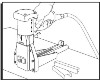
natural_image
Line drawing of a hand using a Bostitch machine to handle a cable, with metal components nearby (no text or symbols)SAFETY

Employer and/or user must ensure that proper eye protection is worn. Eye protection equipment must conform to requirements of the American National Standards Institute ANSI Z87.1 and provide both frontal and side protection.

Eye protection which conforms to ANSI specifications and provides protection against flying particles from both the FRONT and the SIDES should always be worn by the operator and others in the work area when connecting to air supply, loading, operating or servicing this stapler. Eye protection is required to guard against flying fasteners debris which could cause severe eye injury.

WARNING! Non-side shielded spectacles and face shields do not provide adequate protection.
- Use the Bostitch® pneumatic stapler only for the purpose for which it was designed.
- Never use this stapler in a manner that could cause a fastener to be directed toward the user or others in the work area.
- Do not use the stapler as a hammer.
• Always carry the stapler by the handle. Never carry the stapler by the air hose. - Do not alter or modify this stapler from the original design or function without approval from Bostitch Inc.
• Always be aware that misuse and improper handling of this stapler can cause injury to yourself and others. - Never leave unattended with the air hose attached.
-
Do not operate this stapler if it does not have a legible WARNING LABEL.
-
Do not continue to use a stapler that leaks air or does not function properly. Notify Uline if your stapler continues to experience functional problems.
• Always handle the stapler with care
• Never engage in horseplay. - Never pull the trigger unless nose is directed toward the work.
- Keep others at a safe distance from the stapler while in operation as accidental actuation may occur, possibly causing injury.
- Keep hands and body away from the discharge area of the stapler.
- Do not drive fasteners on top of other fasteners or with the stapler at an overly steep angle as this may cause deflection of fasteners which could cause injury.
- This stapler produces SPARKS during operation. NEVER use the stapler near flammable substances, gases or vapors including lacquer, paint, benzene, thinner, gasoline, adhesives, mastics, glues or any other material that is – or vapors which are – flammable, combustible or explosive. Using the stapler in any such environment could cause an EXPLOSION resulting in personal injury or death to user and bystanders.
- Remove all fasteners from the stapler before performing stapler operation check.
- Do not use oxygen, combustible gases or bottled gases as a power source for this stapler, as the stapler may explode, possibly causing injury.
- Do not use supply sources which can potentially exceed 200 psig as stapler may burst, possibly causing injury.
SAFETY CONTINUED
- The connector on the stapler must not hold pressure when air supply is disconnected. If a wrong fitting is used, the stapler can remain charged with air after disconnecting and thus will be able to drive a fastener even after the air line is disconnected, possibly causing injury.
- Do not pull trigger or depress contact arm while connected to the air supply as the stapler may cycle, possibly causing injury.

STOP: Always disconnect air supply:
• Before making adjustments;
- When servicing the stapler;
- When clearing a jam;
- When stapler is not in use;
- When moving to a different work area, as accidental actuation may occur, possibly causing injury.
INSTRUCTIONS
LOADING THE MAGAZINE
- Disconnect from air supply.

WARNING! When loading stapler, never place a hand or any part of the body in fastener discharge area of the stapler. Never point stapler at anyone. Do not pull the trigger or depress the trip as accidental actuation may occur, possibly causing injury.
- Pull back the pusher until it is tucked under the rear of the magazine in position 1. (See Figure 1)
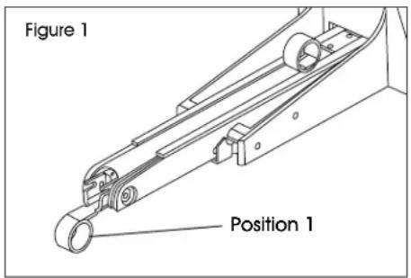
text_image
Figure 1 Position 1- Check staple leg length - Adjustment is provided in the H-3532/H-3534 for different staple leg lengths.
a. To adjust machine for leg length, loosen set screw and turn pivot pin 180° with a screwdriver to the desired adjustment as noted. Tighten set screw. (See Figure 2)
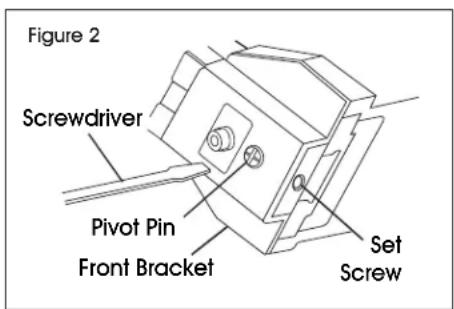
text_image
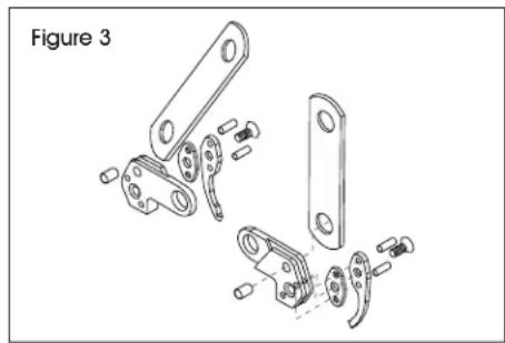
Figure 2 Screwdriver Pivot Pin Front Bracket Set Screwb. To change shallow clinchers (see parts chart for part numbers) remove screws and front bracket to provide access to clinchers. Change one at a time to prevent reversing part. Also part #45 will need to be changed to specified spacer in the table. (See Figure 3)
natural_image
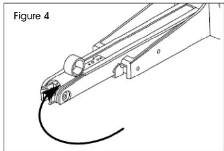
Technical line drawing of mechanical components, showing exploded view with no visible text or symbols- Load the staple stick from the rear of the tool.
- Slide the pusher from position 1 to the rear of the staple stick. (See Figure 4)
natural_image
Technical line drawing of a mechanical assembly with a curved wire and cylindrical component (no text or symbols)INSTRUCTIONS CONTINUED
- Clinch Adjustment – Turn special nut clockwise to tighten clinch and counterclockwise to loosen clinch. Use a tool to fit 1/8" (3 mm) hole. (See Figure 5)

NOTE: Remove adjusting tool after adjustment.

text_image
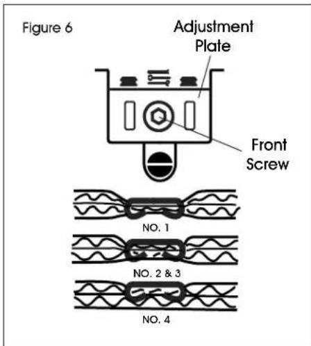
Special Nut Clinch TightLoose Figure 5 Tight Medium Loose- Depth Adjustment – Loosen front screw and adjust to desired length. When the top edge of adjustment plate is at highest setting (#4), the clinchers are at their shallowest penetration. If set at lowest setting (#1), the clinchers are at their deepest penetration. (See Figure 6)

NOTE: Tighten screw after adjusting stapler.
text_image
Figure 6 Adjustment Plate Front Screw NO. 1 NO. 2 & 3 NO. 4OPERATION
TRIGGER-OPERATED STAPLER
a. With finger off the trigger, hold the stapler with a firm grip on the handle.
b. Place the nose of the stapler against the work.
c. Pull the trigger to drive.

WARNING! This is a full-cycle stapler. The stapler will cycle each time the trigger is pulled! Clinchers will discharge and retract.
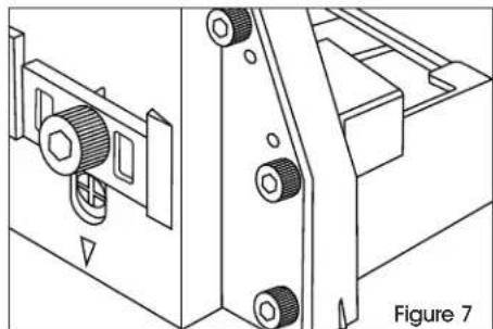
Stapling – Grasp handle with one hand. Position on box in line with the desired staple location. There is a small projection on either side of the frame as an aid in locating the position of the staple. Press trigger. Strongest closure requires end staples close to end of box. Check packaging requirements. Test staple clinching in a sample of the board being used. Adjust clinch for depth of penetration and tightness. (See Figure 7)
natural_image
Technical line drawing of a mechanical assembly with gears and mounting brackets (no text or symbols)
STOP: Always disconnect air supply:
• Before making adjustments;
- When servicing the stapler;
- When clearing a jam;
- When stapler is not in use;
- When moving to a different work area, as accidental actuation may occur, possibly causing injury.
INSTRUCTIONS CONTINUED
REMOVING STUCK STAPLES
STOP
WARNING! Always disconnect air supply before removing stuck stapels
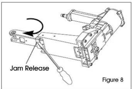
Remove the remaining stick from the magazine. Pry jam release forward with a screwdriver. (See Figure 8)
text_image
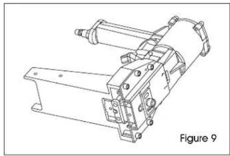
Jam Release Figure 8- Remove magazine. (See Figure 9)
natural_image
Technical line drawing of a mechanical assembly (no text or symbols)- Clear the jam and reinsert the magazine. Pry jam release shut. (See Figure 10)
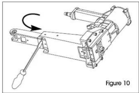
natural_image
Mechanical assembly diagram showing a lever mechanism with a curved arrow indicating rotation (no text or symbols present)MAINTENANCE
STOP
WARNING! When working on air tools, note the warnings in this manual and use extra care evaluating problem tools.
REPLACEMENT PARTS
- Bostitch® replacement parts are recommended. Do not use modified parts or parts which will not give equivalent performance to the original equipment.
ASSEMBLY PROCEDURE FOR SEALS
- When repairing a stapler, make sure the internal parts are clean and lubricated. Use Parker O-LUBE or equivalent on all O-Rings. Coat each O-Ring with O-Lube before assembling. Use a small amount of oil on all moving surfaces and pivots. After reassemble add a few drops of Bostitch Air Tool Lubricant through the air line fitting before sealing.
AIR SUPPLY - PRESSURE AND VOLUME
- Air volume is as important as air pressure. The air volume supplied to the stapler may be inadequate due to undersized fittings and hoses or from the effects of dirt and water in the system. Restricted air flow will prevent the stapler from receiving an adequate volume of air even though the pressure reading is high. The result will be slow operation, misfeeds or reduced driving power. Before evaluating stapler problems for these symptoms, trace the air supply from the stapler to the supply source for restrictive connectors, swivel fittings, low points containing water or anything else that would prevent full volume flow of air to the stapler.
SPECIFICATIONS
STAPLER SPECIFICATIONS
| ULINE PART NO. | MFG. PART NO. | LENGTH | HEIGHT | WIDTH | WEIGHT | STAPLE CAPACITY |
| H-3532 | DS-3219 | 12.6" (320 mm) | 8.86" (225 mm) | 4.5" (115 mm) | 5.45 lbs. (2.45 kg) | 120 |
| H-3534 | DS-3522 | 12.6" (320 mm) | 8.86" (225 mm) | 4.5" (115 mm) | 5.45 lbs. (2.45 kg) | 120 |
FASTENER SPECIFICATIONS
| STAPLER | ULINE PART NO. | LEG LENGTH | STAPLE SERIES | WIRE SIZE | CROWN WIDTH | FASTENER RANGE |
| H-3532 | S-18710 | 5/8" (24 mm) B58C | .074 x 0.37"(1.88 x .94 mm) | 114" (32 mm) | 5/8 - 3/4"(15-19 mm) | |
| S-18711 | 3/4" (29 mm) | B34C | .074 x 0.37"(1.88 x .94 mm) | 114" (32 mm) | 5/8 - 3/4"(15-19 mm) | |
| H-3534 | S-18715 | 5/8" (24 mm) | SW7437 | .074 x 0.37"(1.88 x .94 mm) | 138" (35 mm) | 5/8 - 3/4"(15-19mm) |
| S-18716 | 3/4" (29 mm) | SW7437 | .074 x 0.37"(1.88 x .94 mm) | 138" (35 mm) | 5/8 - 3/4"(15-19 mm) |
PARTS/STAPLE CHART
| MODEL | H-3532/H-3534 | H-3534 | ||
| CLINCHERS | STANDARD/FLAT | DEEP | ||
| A01900601 (L.H.) | A01900501 (R.H.) | A01200601 (R.H.) | A01200601 (L.H.) | |
| SPACERS | A02300801 | A02300801 | — | — |
| STAPLE LENGTHS | 5/8" (16 mm) | 3/4" (19 mm) | 3/4" (19 mm) | 7/8" (22 mm) |
| DIAL POSITION |  |  |  |  |
STAPLER AIR FITTING
This stapler must use a male free-flow connector plug, 1/4" (11 mm) N.P.T. The minimum inside diameter should be .300" (5 mm). Fitting must be capable of discharging stapler air pressure when disconnected from the air supply.
OPERATING PRESSURE
The operating pressure of the stapler is 70 to 100 psi (5 to 7 kg/cm2). Select the operating pressure within this range for best fastener performance.

CAUTION: Do not exceed the recommended operating pressure.
AIR CONSUMPTION
Model H-3532/H-3534 requires 4.0 cubic feet per minute (.113 cubic meters) of free air to operate at the rate of 100 fasteners per minute, at 80 psi (5.66 kg/cm2). Take the actual rate at which the stapler will be run to determine the amount of air required. For instance, if your fastener usage averages 50 fasteners per minute, you need 50% of the stapler's cfm of free air which is required for running at 100 fasteners per minute.
TROUBLESHOOTING
| OPERATING ISSUE CAUSES RECOMMENDATIONS | ||
| Trigger valve housing leaks air. Trigger valve stem leaks air. | O-Ring cut or cracked. O-Ring/seals cut or cracked. | Replace O-Ring. Replace trigger valve assembly. |
| Frame/piston rod leaks air. | O-Ring. Replace O-Ring. | |
| Frame/cap leaks air. | Damaged O-Ring. Loose cap screws. Broken piston. | Replace O-Ring. Tighten and recheck. Replace piston. |
| Lack of power; slow to cycle. | Tool dry, lacks lubrication. O-Rings/seals cut or cracked. Exhaust blocked. Trigger assembly work, leaks. Dirt/tar buildup on driver. Air pressure too low. Worn or misadjusted cycle lever. | Use Bostitch Air Tool Lubricant. Replace O-Rings/seals. Check bumper, head valve spring. Replace trigger assembly. Disassemble nose/driver to clean. Check air supply equipment. Adjust adjustment nut or replace adjustment lever. |
| Skipping fasteners, Intermittent feed. | Tar/dirt in driver channel. Air restriction/inadequate air flow through quick disconnect socket and plug. Worn piston O-Ring/piston. Tool dry, lacks lubrication. Low air pressure. Loose magazine nose screws. Leaking head cap gasket. Trigger valve O-Ring cut/worn. Broken/chipped driver. Worn anvil/pusher. Broken pusher spring. Worn former. Dry/dirty magazine. | Disassemble and clean nose and driver. Replace quick disconnect fittings. Replace O-Ring/piston. Use Bostitch Air Tool Lubricant. Check air supply system to tool. Tighten all screws. Tighten screws/replace gasket. Replace O-Ring. Replace driver (check piston O-Ring). Replace anvil/pusher. Replace pusher spring. Replace former. Clean/lubricate use Bostitch Air Tool Lubricant. |
| Fasteners jam in stapler. | Driver channel worn. Wrong size fasteners. Bent fasteners. Loose magazine nose screws. Broken/chipped driver. Worn former. Worn anvil/pusher. | Replace nose/check door. Use only recommended fasteners. Discontinue using these fasteners. Tighten all screws. Replace driver. Replace former. Replace pusher. |
natural_image
Line drawing of a hand using a BOSTTCH tool to press or install a mechanical component (no text or symbols visible)SEGURIDAD

natural_image
Technical line drawing of mechanical components, no text or symbols presentnatural_image
Technical line drawing of a mechanical assembly with gears and mounting brackets (no text or symbols)
ALTO: Siempre desconecte el suministro de aire:
natural_image
Technical line drawing of a mechanical assembly (no text or symbols)natural_image
Technical line drawing of a mechanical device with a rotating arm and labeled 'Diagrama 10' (no text or symbols on the diagram itself)MANTENIMIENTO

text_image
Figure 1 Position 1natural_image
Exploded view diagram of mechanical components, showing exploded and assembled parts (no text or labels)INSTRUCTIONS SUITE
natural_image
Technical line drawing of a mechanical assembly with a curved wire and cylindrical component (no text or symbols)CHARGEMENT DU MAGASIN, SUITE
natural_image
Technical line drawing of a mechanical assembly with two bolts and a housing (no text or symbols)
RETRAIT D'AGRAFES COINCÉES

natural_image
Technical line drawing of a mechanical assembly (no text or symbols)natural_image
Mechanical assembly diagram showing a lever mechanism with a curved arrow indicating rotational motion (no text or symbols present)ENTRETIEN


