
H-1025 - Stapler Uline - Free user manual and instructions
Find the device manual for free H-1025 Uline in PDF.

User questions about H-1025 Uline
0 question about this device. Answer the ones you know or ask your own.
Ask a new question about this device
Download the instructions for your Stapler in PDF format for free! Find your manual H-1025 - Uline and take your electronic device back in hand. On this page are published all the documents necessary for the use of your device. H-1025 by Uline.
USER MANUAL H-1025 Uline
natural_image
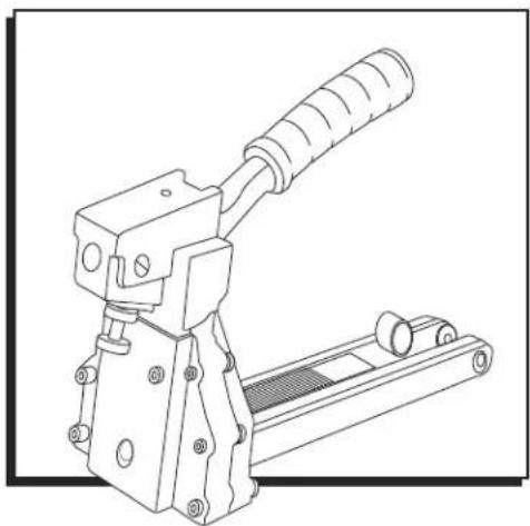
Technical line drawing of a mechanical clamp or crimping tool (no text or symbols)SPECIFICATIONS
| Dimensions (L x H x W) | 15 x 11 12 x 4 12 " |
| Weight (Without Fasteners) | 3.75 lb. |
| H-1025/H-1026 Staple Specification | S-289 C58 Stick and/or S-1396 C34 Stick |
| H-1024 Staple Specification | S-1397 A58 Stick |
| Staple Capacity 100 Staples |
SAFETY
- Read the manual and understand all safety instructions before operating the stapler. If you have questions, contact Uline at 1-800-295-5510.
• Always wear protective equipment; e.g., safety glasses, hearing protection and head protection. - Do not place your hand or any other body part in the staple clinching area.
-
Never point the stapler at yourself or anyone else.
-
Ensure that anyone in the vicinity wears safety protection.
• To prevent accidental injuries, never place a hand or any other body part in the staple clinching area or adjustment window.
• Always handle the stapler with care. Never pull the trigger unless stapler is ready for operation. - Check and replace any damaged or worn components on the stapler.
OPERATION
LOADING THE STAPLER
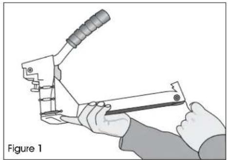
- Pull the pusher back until it stops on pusher pivots. Rotate pusher to position. (See Figure 1)
natural_image
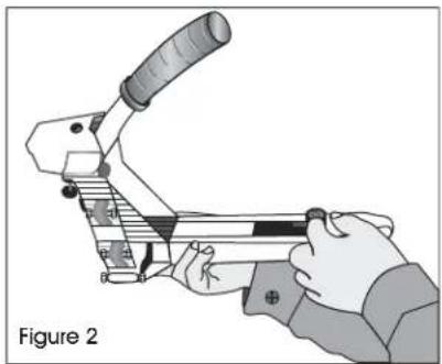
Illustration of hands using a manual tool to handle a mechanical component, labeled 'Figure 1' (no text on the diagram itself)- Insert up to two sticks of appropriate staples into the magazine. Let the sticks slide forward to the front of the magazine. (See Figure 2)
natural_image
Illustration of a hand using a crimping tool, labeled as Figure 2 (no text or symbols on the diagram itself)- Pull the pusher back to an upright position and gently let the pusher slide forward against the staples. Do not let the pusher slide forward and strike the staples at high speed as this may deform the staples and damage the stapler.
ADJUSTING STAPLE LEG LENGTH
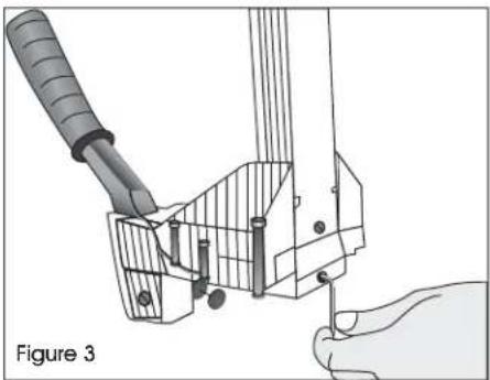
- Loosen set screw with a 3 mm Allen wrench on bottom of stapler. (See Figure 3)
natural_image
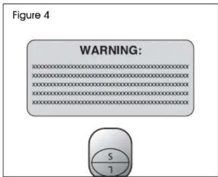
Diagram of a hand holding a tool interacting with a mechanical component, labeled 'Figure 3' (no text or symbols on the diagram itself)- Turn adjusting rod 180° with a screw driver to desired setting. (See Figure 4)

NOTE: If using 3/4" staples, set "L" up.

NOTE: If using 5/8" staples, set "S" up.
text_image
Figure 4 WARNING:- Tighten set screw.
OPERATION CONTINUED
CLINCH ADJUSTMENT
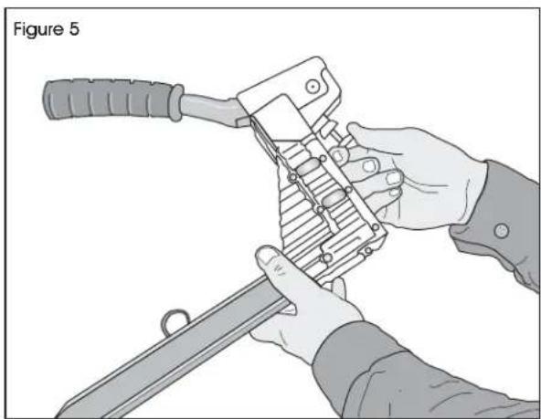
Loosen securing nut closest to body. Turn adjustment nut clockwise to loosen clinch. Turn adjustment nut counterclockwise to tighten clinch. After adjusting, tighten securing nut. (See Figure 5)
natural_image
Illustration of hands using a mechanical tool to handle a sword, labeled 'Figure 5' (no text or symbols on the diagram itself)DEPTH ADJUSTMENT
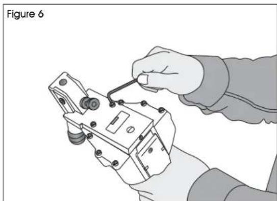
- Loosen front two screws with 4 mm Allen w rench. (See Figure 6)
natural_image
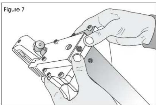
Illustration of a hand using a tool to adjust or install an electrical component (no text or symbols visible)- Push the body up and adjust to the desired depth. (See Figure 7)
natural_image
Illustration of hands using a tool to cut or adjust a metal component, labeled 'Figure 7' (no text on diagram itself)BASIC OPERATION
- Insert the staples into the stapler following the loading instructions.
- Grasp the handle with one hand on box in line with the desired staple location. There is a small projection on either side of the magazine seat as an aid in locating the position of the staple.
- For strongest closure, use staples close to the ends of the box.
CLEARING A JAM
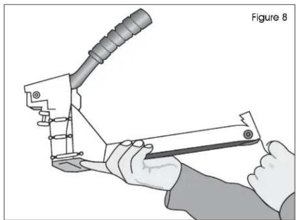
- Pull pusher back and rotate to a locked position. (See Figure 8)
natural_image
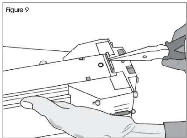
Illustration of a hand using a tool to handle a mechanical component, labeled 'Figure 8' (no text or symbols on the diagram itself)- Insert needle nose pliers or screw driver to clear jam. (See Figure 9)
natural_image
Illustration of hands using scissors to cut or adjust a mechanical component, labeled 'Figure 9' (no text on diagram itself)- Slowly release pusher back to position.
OPERATION CONTINUED
TEETH REPLACEMENT
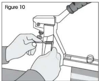
- Loosen screws and nut with 8 mm spanner wrench and 4 mm Allen wrench. (See Figure 10)
natural_image
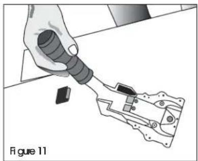
Illustration of hands using a tool to adjust or install a mechanical component, labeled 'Figure 10' (no text on diagram itself)- Remove the magazine assembly. (See Figure 11)
natural_image
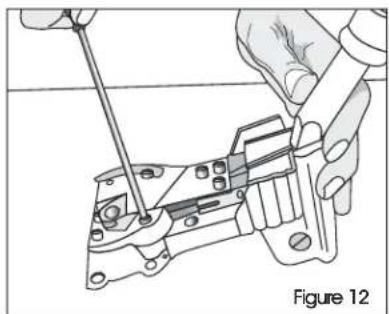
Illustration of a hand using a tool to apply a component into a mechanical housing (no text or symbols visible)- Loosen screws with 3 mm Allen wrench. (See Figure 12)
natural_image
Illustration of hands using a tool to adjust or install a mechanical component, labeled 'Figure 12' (no text or symbols on the diagram itself)- Change teeth one at a time to prevent reverse teeth.
DRIVER REPLACEMENT
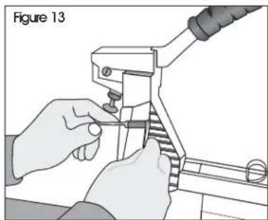
- Loosen screw and nut with 8 mm spanner wrench and 4 mm Allen wrench. (See Figure 13)
natural_image
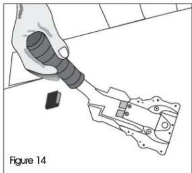
Illustration of hands using a tool to adjust or install a mechanical component (no text or symbols visible)- Remove the magazine assembly. (See Figure 14)
natural_image
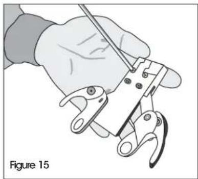
Illustration of a hand holding a flashlight inserted into a mechanical component, labeled Figure 14 (no text or symbols on the diagram itself)- Loosen the set screw with 3mm Allen wrench to unlock the adjusting rod. (See Figure 15)
natural_image
Illustration of a hand using a tool to clamp or grip a wire (no text or symbols present)OPERATION CONTINUED
- Remove the linkage mechanism and adjusting rod simultaneously from the body.
- Loosen the pivot screws with flat screwdriver. Remove handle and linkage mechanism. Remove the spring pin with a hammer and 5 mm straight rod.
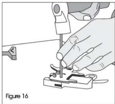
- Loosen screws with a 3 mm Allen wrench. Take off the spring pin with a hammer and 6 mm straight rod. (See Figure 16)
natural_image
Illustration of a hand using a tool to adjust or install a small electronic component, labeled 'Figure 16' (no text on diagram itself)PUSHER SPRING REPLACEMENT
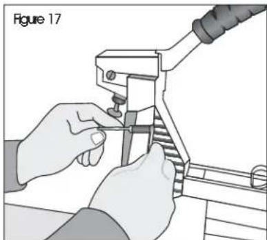
- Loosen the screws and nut with 8 mm spanner wrench and 4 mm Allen wrench. (See Figure 17)
natural_image
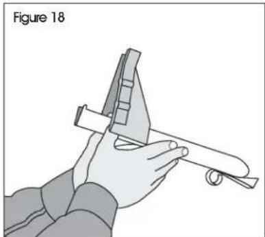
Illustration of hands using a tool to adjust or install a mechanical component (no text or symbols visible)- Remove the magazine assembly. (See Figure 18)
natural_image
Illustration of a hand using a caliper and ruler to measure a mechanical part (no text or symbols)- Pull the pusher back until it stops on the rod, rotate the pusher to position.
- Push the magazine seat back and remove it from the magazine.
- Loosen the screw and nut with 2.5 mm Allen wrench and 7 mm socket wrench. (See Figure 19)

natural_image
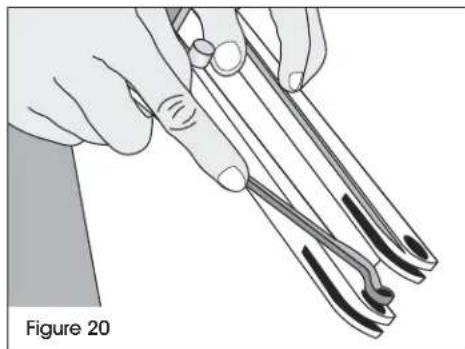
Illustration of a hand using a caliper to measure a cylindrical object, labeled 'Figure 19' (no text or symbols on the diagram itself)- Loosen the rod with a 6 mm offset wrench and remove the pusher guides. Remove the pusher. (See Figure 20)
natural_image
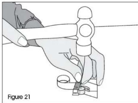
Illustration of hands using tweezers to handle a thin wire, labeled 'Figure 20' (no text on diagram itself)- Remove the spring pin with hammer and 4 mm straight rod. (See Figure 21)
natural_image
Illustration of a hand using a tool to adjust or install a mechanical component, labeled 'Figure 21' (no text or symbols on the diagram itself)TROUBLESHOOTING

WARNING! Stop using the stapler immediately if any of the following problems occur. Serious personal injury could occur. Any repairs or replacements must be done by a qualified person or authorized service center only.
| PROBLEM CAUSE REMEDY | ||
| Excessive jams Teeth screws are loose or staples are wrong size. | Tighten screws and check staples. | |
| Uneven clinch Wrong staple size. | Check for proper leg length adjustment and clincher size. | |
| Unclinched staple Teeth are loose or broken. Check and replace teeth as needed. | ||
natural_image
Technical line drawing of a mechanical clamp or crimping tool (no text or symbols)ESPECIFICACIONES
natural_image
Illustration of a hand using a manual tool to handle a mechanical component, labeled 'Diagrama 1' (no text on the diagram itself)natural_image
Illustration of a hand using a crimping tool to handle a mechanical component (no text or symbols visible)natural_image
Diagram of a hand using a tool to adjust or install a mechanical component, labeled 'Diagrama 3' (no text on diagram itself)natural_image
Illustration of hands using a folding tool to handle a sword, labeled 'Diagrama 5' (no text on diagram itself)natural_image
Illustration of a hand using a tool to adjust or install an electrical component (no text or symbols visible)natural_image
Illustration of hands using a pliers to cut or adjust a mechanical component (no text or symbols visible)natural_image
Illustration of a hand using a manual tool to handle a mechanical component, labeled 'Diagrama 8' (no text on the diagram itself)natural_image
Illustration of hands using a pliers to adjust or install a mechanical component (no text or symbols visible)natural_image
Illustration of a hand using a tool to apply a component into a mechanical housing (no text or symbols visible)natural_image
Technical illustration of hands using a tool to adjust or install a mechanical component (no text or symbols visible)natural_image
Illustration of hands using a tool to adjust or install a mechanical component (no text or symbols visible)natural_image
Illustration of a hand using a tool to interact with a mechanical device (no text or symbols visible)natural_image
Illustration of a hand using a tool to clamp or grip a wire (no text or symbols visible)natural_image
Illustration of a hand using a tool to adjust or install a small electronic component, labeled 'Diagrama 16' (no text on diagram itself)REMPLAZO DEL RESORTE DEL EMPUJADOR
natural_image
Illustration of hands using a pliers to adjust or install a mechanical component (no text or symbols visible)natural_image
Illustration of a hand using a caliper to measure a mechanical part (no text or symbols present)natural_image
Illustration of hands using tweezers to handle a tool, labeled 'Diagrama 20' (no other text or symbols)natural_image
Illustration of a hand using a tool to cut or repair a mechanical component, labeled 'Diagrama 21' (no other text or symbols)natural_image
Technical line drawing of a mechanical clamp or crimping tool (no text or symbols)SPÉCIFICATIONS
| Dimensions (long. x haut. x larg.) | 38,1 x 29,2 x 11,4 cm (15 x 1112 x 412 po) |
| Poids (sans Agrafes) 1,7 kg (3,75 lb) | |
| Spécifications des agrafes H-1025/H-1026 Bande S-289 | C58 et/ou bande S-1396 C34 |
| Spécifications des agrafes H-1024 Bande S-1397 A58 | |
| Capacité d'Agrafes 100 agrafes |
SÉCURITE
natural_image
Illustration of a hand using a crimping tool to handle a mechanical component, labeled 'Figure 1' (no text on the diagram itself)natural_image
Illustration of a hand using a crimping tool to handle a mechanical component, labeled 'Figure 2' (no text or symbols on the diagram itself)natural_image
Technical illustration of a mechanical assembly with tool and base components, labeled Figure 3 (no text or symbols on the diagram itself)text_image
Figure 4 WARNING: S 7natural_image
Illustration of hands using a tool to handle a metal object, labeled 'Figure 5' (no text or symbols on the diagram itself)natural_image
Illustration of a hand using a tool to adjust or install an electrical component (no text or symbols visible)natural_image
Illustration of hands using a power tool to cut or adjust a mechanical component (no text or symbols visible)OPÉRATION DE BASE
natural_image
Illustration of a hand using a manual tool to handle a mechanical component, labeled 'Figure 8' (no text or symbols on the diagram itself)natural_image
Illustration of hands using scissors to cut or adjust a mechanical component, labeled 'Figure 9' (no text on diagram itself)natural_image
Illustration of hands using a tool to adjust or install a mechanical component, labeled 'Figure 10' (no text on diagram)- Retirez le magasin. (Voir Figure 11)

natural_image
Hand using a tool to apply a component to a mechanical part (no text or symbols visible)natural_image
Technical line drawing of a mechanical assembly with hands operating a tool (no text or symbols present)natural_image
Illustration of hands using a crimping tool to adjust or install a component, labeled 'Figure 13' (no text on diagram itself)- Retirez le magasin. (Voir Figure 14)

natural_image
Illustration of a hand using a tool to interact with a mechanical device (no text or symbols visible)natural_image
Illustration of a hand using a tool to clamp or wire from a mechanical component, labeled 'Figure 15' (no text on the diagram itself)OPERATION SUITE
natural_image
Illustration of a hand using a tool to adjust or install a small component, labeled 'Figure 16' (no text on diagram itself)REPLACEMENT DU RESSORT DE POUSSEUR
natural_image
Illustration of hands using a tool to adjust or install a mechanical component (no text or symbols visible)natural_image
Illustration of a hand using a protractor and ruler to measure a mechanical part (no text or symbols)natural_image
Illustration of a hand using a tool to measure a mechanical component, labeled 'Figure 19' (no text or symbols on the diagram itself)natural_image
Illustration of hands using surgical forceps to draw a curved object, labeled 'Figure 20' (no text on diagram itself)natural_image
Illustration of a hand using a sewing machine to cut a piece of paper (no text or symbols visible)DÉPANNAGE


