H-1440 - Stapler Uline - Free user manual and instructions
Find the device manual for free H-1440 Uline in PDF.

User questions about H-1440 Uline
0 question about this device. Answer the ones you know or ask your own.
Ask a new question about this device
Download the instructions for your Stapler in PDF format for free! Find your manual H-1440 - Uline and take your electronic device back in hand. On this page are published all the documents necessary for the use of your device. H-1440 by Uline.
USER MANUAL H-1440 Uline
natural_image
Illustration of a stapler tool with handle and base (no text or symbols)SAFETY

WARNING! Read all warnings and instructions to prevent injuries to yourself and to others.
- Use only original Kihlberg stick staples
- Wear eye protection when using tool. Always use other personal protection equipment as required, such as ear protection, hard hats, etc.
- Never use oxygen, combustible gases, CO_2 , steam or high pressure gas tanks as power sources for the PN-version of this tool; the tool may explode and cause serious injury. Use only dry, clean, pressure regulated compressed air to drive the tool.
-
Always disconnect the tool from the air supply and empty the magazine when taking a break or ending work, when servicing the tool, troubleshooting or repairing. Never leave a loaded tool unattended.
-
Always assume that the tool is loaded. Respect the tool as potentially dangerous. Never point the tool at yourself or anyone else, whether it contains staples or not. Always remove finger from trigger when not driving staples.
• Always check tool before every use. - Never hold your hand or another part of your body under the tool.
- Position yourself in a firmly balanced position when using or handling the tool.
- Do not modify the tool or set it up in a jig without manufacturer's approval.
- Use stapler with cardboard only. No other use is permitted without the approval of the manufacturer.
OPERATION
ATTACH COMPRESSED AIR

CAUTION! Ensure the tool is not pointed at you or anyone else when connecting it to the compressed air line.

NOTE: The maximum permitted air pressure for the tool is 8 bar (116 psi). The maximum supply pressure is 8.78 bar (127 psi).
Connect the tool to the compressed air system before the fastener unit is loaded.

NOTE: The tool and its hose can be equipped with a connection nipple (not included) that automatically exhausts air from the tool after it has been disconnected.
Ensure the minimum internal diameter of the air hose is 10 mm (3/8") and that of the nipple is a minimum of 5 mm (6/32"). This prevents incorrect operation due to excessive pressure drop.
AIR PRESSURE
Adjust the air pressure to the lowest setting that will bend the staples correctly.
- Start at 5.0 bar (72 psi).
- Raise pressure by 0.5 bar (7 psi) increments until correct pressure for the job is found.

CAUTION! Never exceed 8 bar (116 psi).
OPERATION CONTINUED
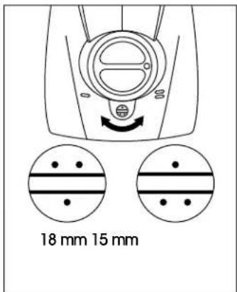
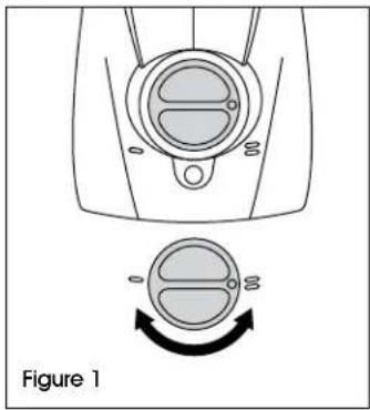
STAPLE PENETRATION DEPTH
Push knob in and turn to the desired position: (See Figure 1)
- For shallow stapling
= For deep stapling
natural_image
Diagram of a mechanical component with a circular dial and rotation arrow, labeled Figure 1 (no text or symbols on the diagram itself)STAPLE LEG LENGTH
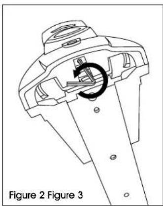
Stapler adapts to use of 15 or 18 mm staples.
- Loosen the locking screw underneath with 2.5 mm Allen wrench. (See Figure 2)
- Set desired staple leg length. Tighten the locking screw. (See Figure 3)
natural_image
Technical line drawing of a mechanical component with a circular arrow indicating rotation (no text or symbols)
text_image
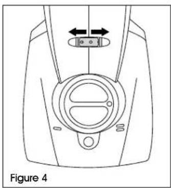
18 mm 15 mmSTAPLE CLOSURE
For a tighter staple closure: Turn the adjusting nut to the left. (See Figure 4)
For a looser staple closure: Turn the adjusting nut to the right. (See Figure 4)
natural_image
Technical line drawing of a device component with directional arrows indicating movement (no text or symbols)LOADING
- Pull and lock pusher to rear of magazine. (See Figure 5)
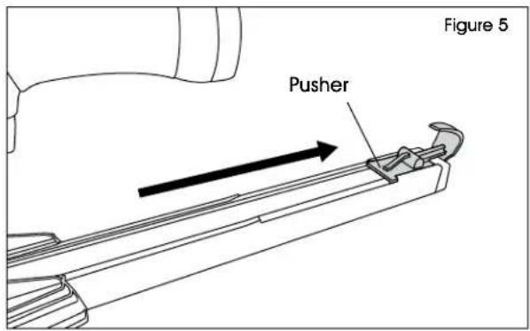
text_image
Figure 5 Pusher- Insert two sticks of staples into the magazine. (See Figure 6)
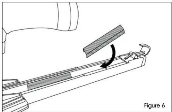
natural_image
Technical line drawing of a mechanical component with a clamping tool and directional arrow (no text or symbols)- Lift latch to release pusher. Ease pusher forward until contact is made with staples in magazine. (See Figure 7)
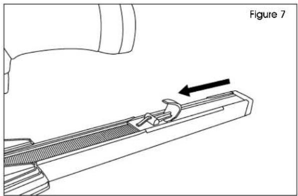
natural_image
Technical line drawing of a mechanical component with an arrow indicating direction (no text or symbols present)OPERATION CONTINUED
STAPLING
-
Place tool against box and press down until surface is compressed.
-
Pull the trigger.

NOTE: One staple will be dispensed per trigger pull.
MAINTENANCE

WARNING! Always disconnect the tool from the air supply, empty magazine and read safety warnings before starting any maintenance.

CAUTION! Do not remove any parts for cleaning purposes.
This tool does not require special servicing and only needs regular cleaning with a non-corrosive cleaning agent.
DAILY:
Check the proper functioning of all safety devices. Carefully inspect the following:
- Trigger and safety yoke move freely without binding or sticking.
- All screws and nuts are securely tightened.
LUBRICATION
Use a small amount of lubricating oil in the nipple each day (approximately 10 drops once a week) to ensure safe function.
Grease sliding or moving parts with multipurpose grease if they have been cleaned or replaced.
CLEARING JAMS
Generally, you will not need to disassemble any parts to clear jamming in the nozzle plate.
- Grip the staple with a pair of flat-nosed pliers at the exit from the front nozzle plate. (See Figure 8)
- Carefully remove the staple with flat pliers. (See Figure 8)
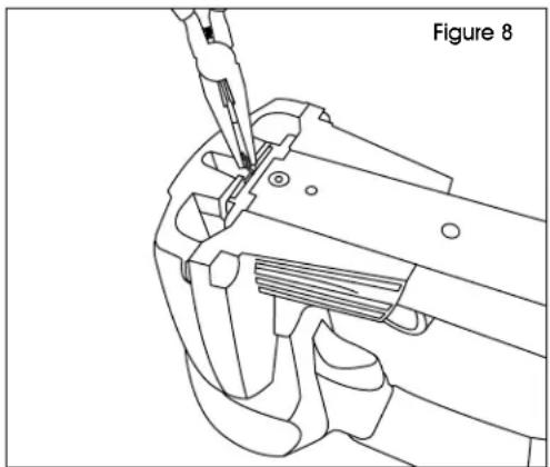
natural_image
Technical line drawing of a mechanical tool or clamp assembly (no text or symbols)ULIN4D
KIHLBERG ENGRAPADORA NEUMÁTICA EN TIRAS
natural_image
Illustration of a stapler tool with handle and base (no text or symbols)SEGURIDAD

natural_image
Illustration of a stapler tool with handle and base (no text or symbols)CONSIGNES DE SÉCURITÉ
ARRÊT
natural_image
Diagram of a mechanical component with a circular dial and rotation arrow, labeled Figure 1 (no text or symbols on the diagram itself)LONGUEUR DES PATTES D'AGRAFE
natural_image
Technical line drawing of a mechanical component with a circular arrow indicating rotation (no text or symbols)