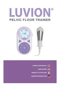
Pelvic Floor Trainer - Medical device Luvion - Free user manual and instructions
Find the device manual for free Pelvic Floor Trainer Luvion in PDF.


| Product type | Medical device for pelvic floor rehabilitation with EMS and TENS |
| Brand | Luvion |
| Model | Pelvic Floor Trainer (Intrelief PFE) |
| Main use | Strengthening the pelvic floor, postnatal recovery, improving bladder control, relieving muscle pain |
| Technology | EMS (Electrical Muscle Stimulation) and TENS (Transcutaneous Electrical Nerve Stimulation) |
| Output channels | 2 independent channels (CH1, CH2) |
| Programs | 17 predefined (P1 to P17) with durations from 10 to 60 minutes |
| Pulse frequency | 2–200 Hz |
| Pulse width | 75–500 μs |
| Maximum intensity | 80 mA (peak) into 500 ohms, 40 V |
| Power supply | 2 AA alkaline batteries 1.5V (LR6) |
| Included accessories | Stimulation unit, vaginal probe, 4 adhesive electrodes, 2 connection cables, probe cable, 2 AA batteries, carrying case, user manual |
| Available spare parts | Vaginal probe VP01, connection cables, adhesive electrodes (pack of 4), AA batteries |
| Maintenance and cleaning | Clean the probe after each use with lukewarm soapy water; do not immerse the unit; clean cables and case once a week |
| Safety | Contraindicated in case of pacemaker, implanted defibrillator, pregnancy, epilepsy, etc. Consult a doctor before use |
| Warranty | 1 year against material and manufacturing defects |
| Standards | CE, compliant with EU regulation 2017/745, class IIa |
| Weight (estimated) | Approximately 150 g (without batteries) |
| Dimensions (estimated) | Approximately 12 x 6 x 3 cm |
Frequently Asked Questions - Pelvic Floor Trainer Luvion
User questions about Pelvic Floor Trainer Luvion
0 question about this device. Answer the ones you know or ask your own.
Ask a new question about this device
Download the instructions for your Medical device in PDF format for free! Find your manual Pelvic Floor Trainer - Luvion and take your electronic device back in hand. On this page are published all the documents necessary for the use of your device. Pelvic Floor Trainer by Luvion.
USER MANUAL Pelvic Floor Trainer Luvion
Thank you for purchasing the Luvion® Pelvic Floor Trainer. This 2-in-1 device combines EMS (Electrical Muscle Stimulation) and TENS (Transcutaneous Electrical Nerve Stimulation) technologies to support your pelvic health, muscle strength and recovery. This combined stimulation helps strengthen these muscles that may have weakened over time due to pregnancy, aging or other factors.
- EMS works through the vaginal probe to trigger muscle contractions and strengthen the pelvic floor.
- TENS uses electrode pads to deliver gentle pulses that relieve muscle tension, reduce pain, and support recovery of the pelvic floor muscles.
This device is especially helpful for: supporting postpartum pelvic recovery; enhancing sensations during intimacy by improving muscle tone; and improving bladder and bowel control, reducing risks of incontinence.
For more information, visit www.luvion.com. This manual explains how to use the device safely and effectively. Please read it carefully and pay special attention to the safety instructions.
Intended use: this is a medical device designed to be used in the home healthcare environment to enhance muscle tone and bulk, support muscular training, and provide symptomatic relief and management of acute or chronic localised pain and muscle pain. It is suitable for use by all who can control the device and understand the instructions. Do not use the device for any purpose other than this intended use.
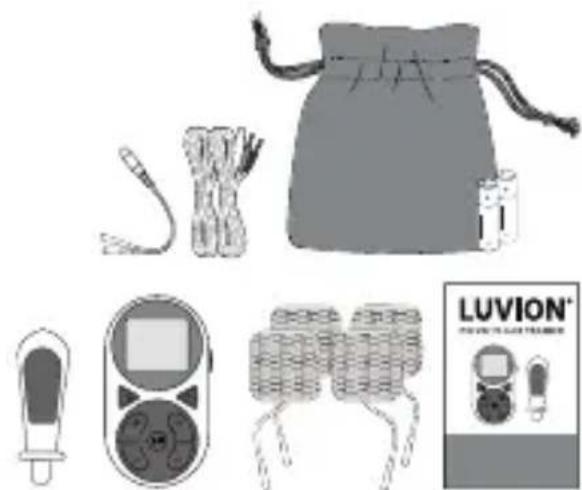
PACKAGE CONTENTS
• 1x Stimulator Unit
- 1x Vaginal Probe
• 4x Electrode Pads
• 2x Connection Wires
- 1x Probe lead
- 2x Batteries (AA)
- 1x Travel Pouch
- 1x User Manual
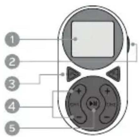
OVERVIEW OF THE STIMULATOR UNIT
- Screen
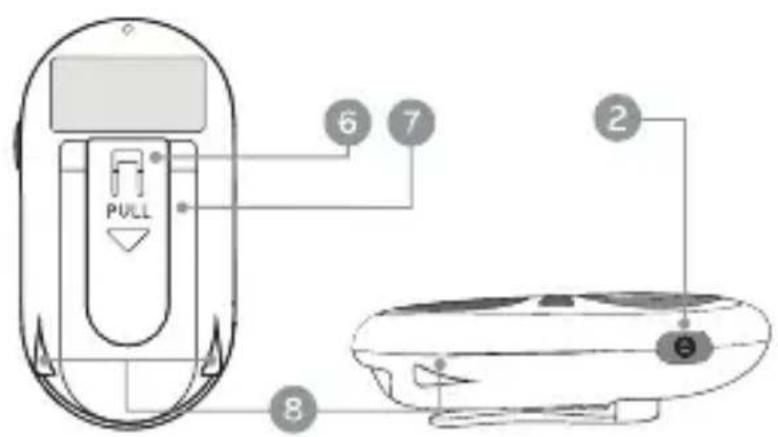
- Power Button
- Program Selection Buttons
- Increase/Decrease Intensity Button
- Play/Pause Button
- Clothes Clip
- Battery Compartment
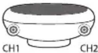
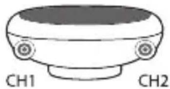
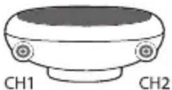
- Channel 1 and 2 (CH1 and CH2) Jack Ports
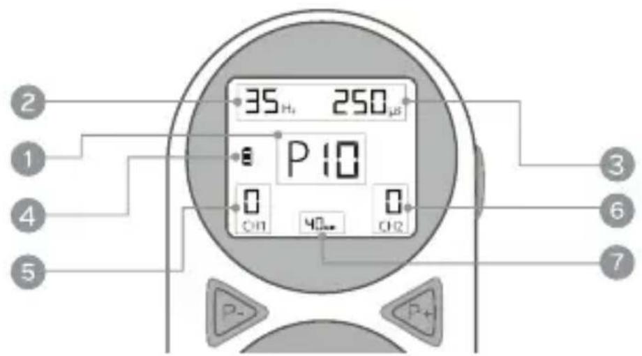
OVERVIEW OF THE SCREEN DISPLAY
- Selected Program
- Pulse Rate (Hz)
- Pulse Width (μs)
- Battery Status
- CH1 Intensity Level
- CH2 Intensity Level
- Session Timer
SAFETY INSTRUCTIONS

CONTRAINDICATION:
- Do NOT use if you have a cardiac pacemaker, implanted defibrillator, or other implanted metallic or electronic device. Such use could cause electric shock, burns, electrical interference or death.

WARNING:
- The long-term effects of chronic electrical stimulation are unknown.
- If you have had medical or physical treatment for your pain, consult with your physician before using this device.
- If your pain does not improve, becomes more than mild or continues for more than five days, stop using the device and consult with your physician.
- Do NOT apply stimulation to the front or sides of the neck where the carotid sinus nerves are located, particularly in patients with a known sensitivity to the carotid sinus reflex. Stimulation to this part of the body may have serious effect on heart rate or blood pressure.
- Do NOT apply stimulation over the neck or mouth. Severe spasm of the laryngeal and pharyngeal muscles may occur and the contractions may be strong enough to close the airway or cause difficulty in breathing, or adverse effects on heart rhythm or blood pressure.
- Do NOT apply stimulation across the chest from front to back or side to side. Applying electrical stimulation across the chest may introduce current to the heart which could result in heart rhythm disturbances (cardiac arrhythmias) which may be lethal.
- Stimulation should not be applied to the head, this includes the face and eyes. The effects of stimulating the head are unknown.
- Do NOT apply electrodes on the chest near the heart because the introduction of electrical current to the heart may increase the risk of cardiac arrhythmias.
- Stimulation should not be applied to the upper back or across the upper back near the heart.
- Do NOT place electrodes directly over the backbone or spine.
- Do NOT place electrodes directly over a joint, such as the wrist, knee, ankle, etc. Only place electrode pads on muscular areas of the body.
- Do NOT apply stimulation over open wounds or rashes, or over swollen, red, infected or inflamed areas or skin eruptions (e.g., phlebitis, thrombophlebitis, varicose veins).
- Do NOT apply stimulation over or in proximity to cancerous lesions.
- Do NOT apply stimulation in the presence of electronic monitoring equipment (e.g., cardiac monitors, ECG alarms), which may not operate properly when the electrical stimulation device is in use.
- Do NOT apply stimulation when in the bath or shower.
- Do NOT apply stimulation while sleeping.
- Do NOT apply stimulation while driving, operating machinery or during any activity in which electrical stimulation or involuntary muscle contractions can put you at risk of injury.
- Do NOT use the device on children. The safety for use on children has not been established.
- Consult with your physician before using this device, because the device may cause lethal rhythm disturbances to the heart in susceptible individuals.
- Apply stimulation only to normal, intact, clean, healthy skin.
- Do NOT put the lead wire on or wrapped around the neck. Placing the lead wires on the neck or wrapped around the neck may cause strangulation.
- Keep TENS and EMS devices out of the reach of children, the small parts may present a choking hazard or the lead wires could cause strangulation.
- Repair or replacement of parts by inadequately trained personnel could result in a hazard.
- No modification of this equipment and accessories is allowed. Replacement of parts or repair of this equipment should only be performed by authorized agents. The only parts that can be replaced by the end user are the electrodes, lead wires or batteries.

PRECAUTIONS:
- TENS is a symptomatic treatment, as such suppresses the sensation of pain, that would otherwise serve as a protective mechanism.
- TENS is not a substitute for pain medications and other pain management therapies.
- TENS devices have no curative value. The long-term effects of electrical stimulation are unknown. Effectiveness is highly dependent upon patient selection by a practitioner qualified in the management of pain patients.
- Since the effects of stimulation of the brain are unknown, stimulation should not be applied on the head.
- The safety of electrical stimulation during pregnancy has not been established.
- You may experience skin irritation or hypersensitivity due to the electrical stimulation or electrical conductive medium (gel). The irritation can usually be reduced by using an alternate conductive medium, or alternate electrode placement.
- If you have suspected or diagnosed heart disease, you should consult your
physician prior to using this device.
- If you have suspected or diagnosed epilepsy, you should consult your physician prior to using this device.
- Consult with your physician and use caution if you have a tendency to bleed internally, such as following an injury or fracture.
- Consult with your physician prior to using the device after a recent surgical procedure, because stimulation may disrupt the healing process.
- Use with caution if stimulation is applied over the menstruating uterus.
- Use with caution if stimulation is applied over areas of skin that lack normal sensation.
- Keep this device out of the reach of children and pets.
- Use this device only with the leads, electrodes and accessories recommended by the manufacturer.
- Do NOT connect this device to other equipment not described in the instructions for use, this could be unsafe.
- Do NOT use this device with high frequency diathermy devices or high frequency surgical devices, this may result in burns under the electrodes and damage the device.
- Operation in close proximity (e.g. 1 meter) to a shortwave or microwave diathermy therapy equipment may produce instability in the stimulator output.

ADVERSE REACTIONS:
- You may experience skin irritation and burns beneath the stimulation electrodes applied to your skin.
- Application of electrical stimulation to the head has resulted in headaches and other painful sensations. Do not apply TENS or EMS to the head.
- You should stop using the device and should consult with your physician if you experience adverse reactions from the device.

GENERAL WARNINGS AND INSTRUCTION FOR DEVICE
MAINTENANCE:
- Do NOT immerse any part of this unit in water.
- Do NOT place the unit close to excessive heat.
- Do NOT use any electrodes which sizes are less than 50mm x 50mm.
- Use only the specified battery: 2 x 1.5 volt AA Alkaline. Using of any other battery could damage the unit.
- Remove battery if unit is not used for a long period of time.
- Use this device only with electrodes and accessories recommended by the
manufacturer. Using other parts/materials supplied by other manufacturer can degrade minimum safety.
- Keep the unit away from sources of high magnetic fields such as TV's, microwave ovens and hi-fi speakers, as these may affect the LCD screen.
- Keep the device away from a fireplace or radiant heater, as the heat may affect the device.
- Keep the device away from nebulizer or steam kettle, as the moisture may affect the device.
- Keep the device away from sunlight, as long-term exposure to sunlight may affect the rubber become less elastic and cracked.
- Keep the device away from lint and dust, as long-term exposure to lint or dust may affect the plug/sockets or connector become bad contact.
HOW TO USE
STEP 1: Insert the Batteries
- Slide down the clip and the back cover of the stimulator unit to access the battery compartment.
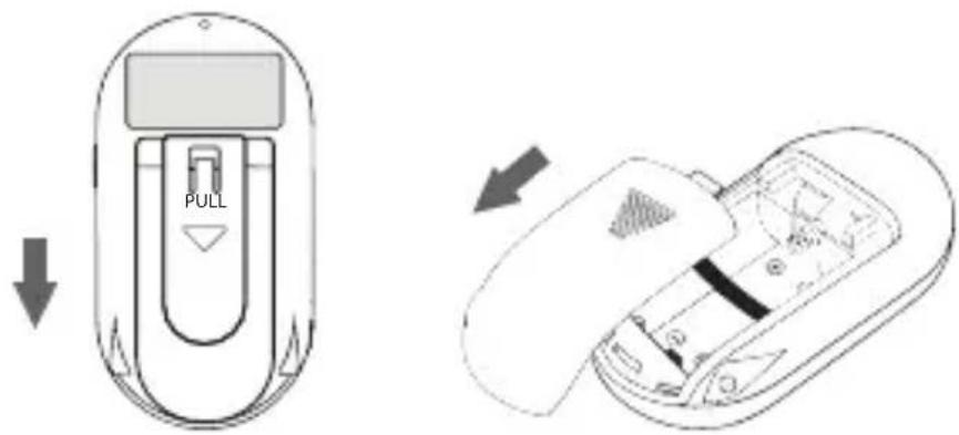
- Insert two AA 1.5 V alkaline batteries, matching the polarity indicators. Ensure that the batteries are inserted correctly as shown in the battery compartment and that the ribbon is behind them.
- Put back the battery cover and clip.
A low battery icon on the screen will indicate when replacements are needed. Change the batteries as soon as possible.

CAUTION:
There is a risk of explosion if the batteries are fitted incorrectly. Replace with AA Alkaline 1.5 V batteries (LR6). Do not mix old and new batteries. Do not dispose of the batteries in a fire and keep them out of reach of children. Remove the batteries if the device will be unused for an extended period.
STEP 2: Connect the Wires
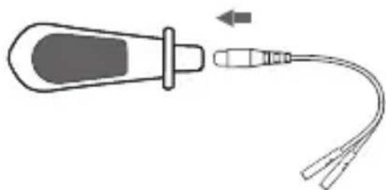
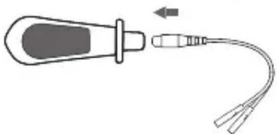
- Plug the white end of the connection wire into one of the jack ports on the bottom of the stimulator unit.

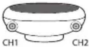
Each jack port on the bottom of the device corresponds to a separate output: CH1 on the left and CH2 on the right.
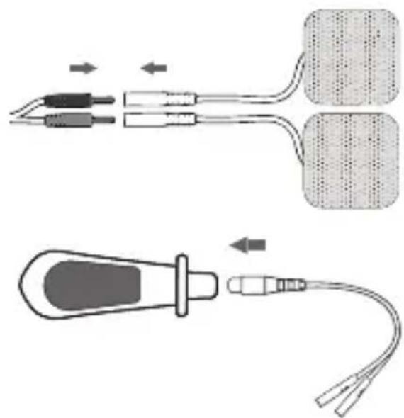
2.1. Using Electrode Pads: connect the coloured ends of the connection wires to the electrode pads (for TENS mode). Each wire end should connect to one pad.
2.2. Using the Vaginal Probe: connect the probe lead to the vaginal probe (for EMS mode), then attach the coloured ends of the connection wires to the probe lead.
STEP 3: Apply the Accessory
3.1. Pelvic Floor Training using the Vaginal Probe
- Use programs P1–P13 with the vaginal probe.
-
Ensure the stimulator unit is powered OFF during both insertion and removal of the probe.
• Empty your bladder before use. -
Apply a water-based lubricant to the vaginal probe.
- Get into a comfortable position, lying down with your knees bent and your feet flat. Gently insert the probe into the vagina. Insert the probe like a tampon, leaving only the base flange visible.
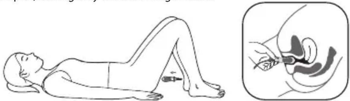
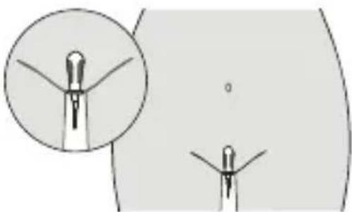
- The wider side of the flange should remain vertical inside the body. Ensure the metal sides of the probe are facing towards your hips.
• The metal parts of the probe conduct the electrical pulse and should be in
contact with the main part of the muscle at all times. The tissues close to the entrance are more sensitive, so you should avoid stimulating them.

CAUTION:
Initially the sensation through the probe may be limited but will improve during treatment. Avoid overstimulation – start with a low intensity and increase gradually. The sensation may not be even as it may vary depending on the sensitivity of the nerves.
Note: the vaginal probe is intended for single-patient use only to prevent cross-contamination.
3.2. Muscle Recovery using the Electrode Pads
- Use programs P14–P17 with the electrode pads.
- Ensure the stimulator unit is powered OFF during both placement and removal of the electrode pads.
- Peel off the protective film of the electrode pads. Avoid touching the gel directly to maintain adhesion.
-
Apply the pads to clean, dry skin on the target area (e.g., abdomen, waist, arms, thighs, hips).
-
Please refer to Table 1 (page 14) for a description of the programs and target areas.
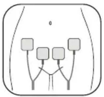
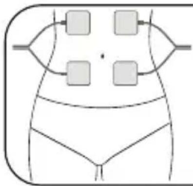
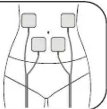
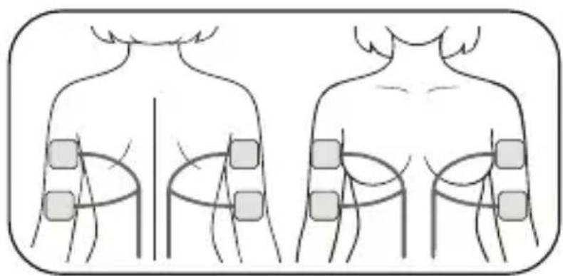
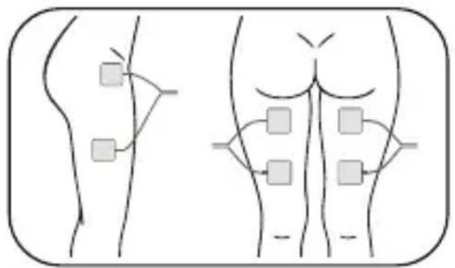
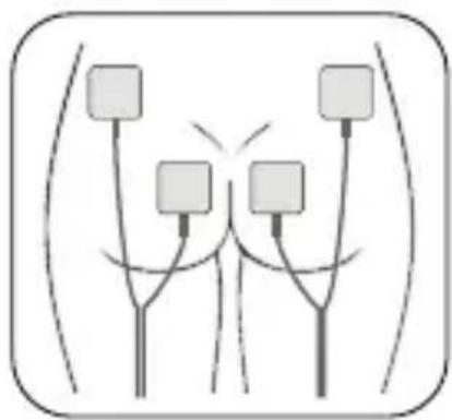
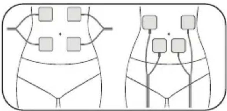
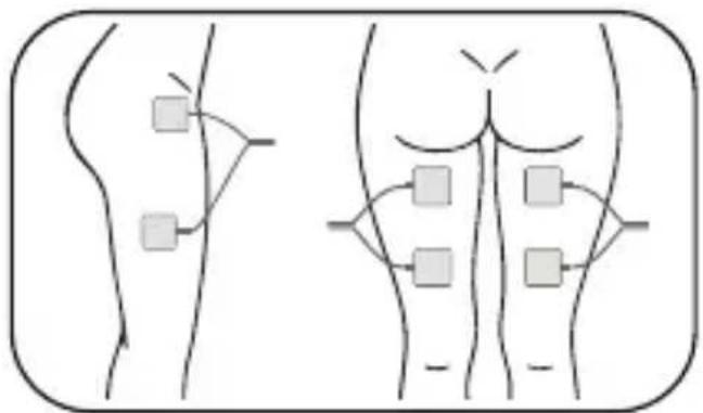
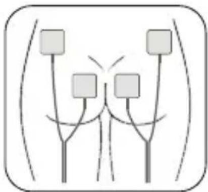
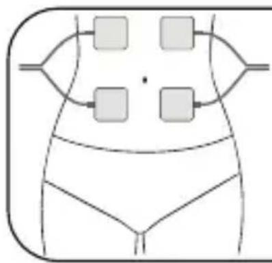
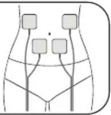
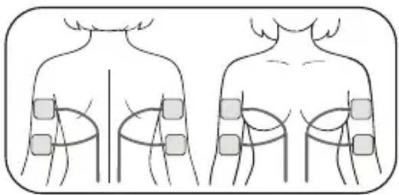
- Select the appropriate program mode based on your symptoms, then place the electrodes on the specific treatment area following the body map diagrams below, which illustrate correct electrode placement.
3.3. Electrode Pads Placement
Waist (Program P14)
![graph TD A["Left Body Region"] --> B["Node 1"] A --> C["Node 2"] A --> D["Node 3"] A --> E["Node 4"] B --> F["Loop Path"] C --> F D --> F E --> F F --> G["Right Body Region"] G --> H["Node 1"] G --> I["Node 2"] G --> J["Node 3"]](/content/2026/05/754816/images/a8baf1851130c72124cb63c6b1fbcda6fd5873e08e7bf77b8d539e2eda7219cd.jpg)
Upper Arm (Program P15)

Thighs (Program P16)
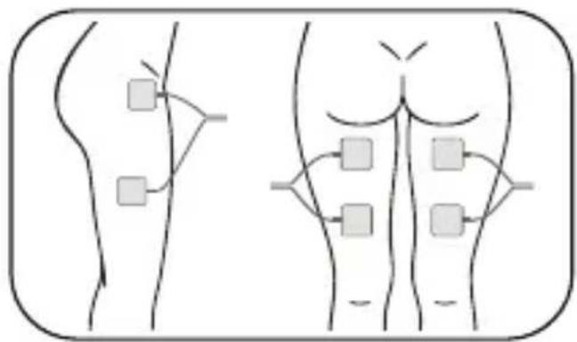
Hip (Program P17)
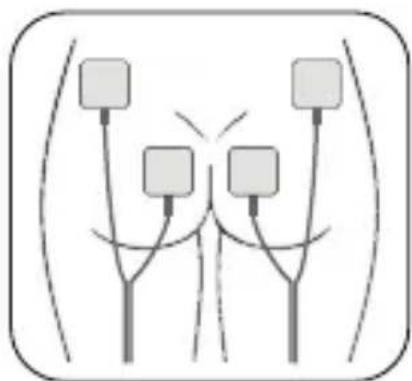
Note: the electrodes that are supplied are latex-free, self-adhesive and can be used several times. Skin must be allowed to breathe, so the electrodes should be removed periodically. When not in use, the electrodes should be placed onto the clear plastic protective film.

CAUTION:
- The electrodes supplied are reusable but are for single patient use.
- The condition of the electrodes has a direct effect on conductivity, and therefore the effectiveness of the treatment. Poor connection may cause discomfort and skin irritation.
- If the electrodes dry out then it is best to buy a replacement pack of electrodes.
- In an emergency it may be possible to restore some of the adhesiveness by applying a fine spray of water to the gel side of the electrode. If too much water is added the electrodes will become too soft. If this occurs, simply place the electrodes sticky side up in a refrigerator for a few hours. In time, this technique will not work, the gel will not reactivate, and new electrodes should be used.
- In very hot weather the gel on the electrodes may become soft. In such cases place the electrodes, still on their plastic liners and in their bag, into a fridge until they return to their normal condition.
- Storage life of an unopened pack of electrodes is 3 years. This may be affected by very high temperatures or very low humidity.
• Maximum output values available at the electrodes is 40V across 500 Ohm.
STEP 4: Power On the Device
4.1. Turn On/Off:
- Press and hold the lateral power button Ⓞ of the stimulator unit for 3 seconds until the screen lights up.
- The unit will start in standby mode with intensity set to zero.
- To switch off, press and hold the same button for 3 seconds again. The screen will turn off.
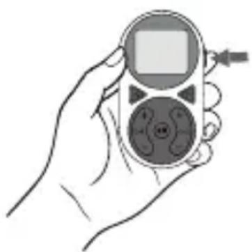
Note: the unit automatically remembers the last program used. When turned back on, it resumes from that program unless changed.
4.2. Selecting a Program:
- Use the P1 and buttons to scroll through the 17 programs (P1–P17).
• Refer to the program guide in Table 1 for a description of recommended uses.
Each program has a specific use case:
- P1–P5: pelvic floor training for incontinence.
- P6–P7: pelvic floor strengthening and toning.
- P8–P13: relaxation, sensitivity and endurance training for the pelvic floor.
- P14–P17: external muscle recovery of waist, limbs and hip.
Table 1: Program guide
| MODE | PULSE RATE (Hz) | PULSE WIDTH (μs) | TIME (min) | OBJECTIVE | ACCESSORY TO BE USED |
| P1 | 35 | 250 | 40 | Treatment of stress incontinence* (level 1) | Vaginal Probe |
| P2 50 | 250 60 | Treatment of stress incontinence (level 2) | Vaginal Probe | ||
| P3 | 5 | 250 | 10 | Treatment of urge incontinence** (level 1) | Vaginal Probe |
| P4 | 10 | 250 | 10 | Treatment of urge incontinence (level 2) | Vaginal Probe |
| P5 | 35 | 250 | 20 | Treatment of mixed incontinence*** | Vaginal Probe |
| P6 30 | 400 | 20 | Strengthen the pelvic floor muscles to avoid Pelvic Organ Prolapse (POP) | Vaginal Probe | |
| P7 35 | 250 | 20 | Exercise the pelvic floor muscles and rehabilitate Pelvic Floor Dysfunction (PFD) | Vaginal Probe | |
| P8 | 2 | 250 | 10 | Relaxation of the pelvic floor muscle | Vaginal Probe |
| P9 | 50 | 300 | 20 | Exercise and tighten pelvic floor muscles | Vaginal Probe |
| P10 4-35 | 240-30 | 30 | Exercise pelvic floor muscles and improve endurance | Vaginal Probe | |
| P11 30 | 25 | 20 | Exercise to strengthen and tighten the vaginal muscles | Vaginal Probe | |
| P12 | 3-40 | 200-250 | 25 | Improve pelvic sensitivity | Vaginal Probe |
| P13 | 75 | 100 | 20 | Relieve the pelvic pain due to muscle strain | Vaginal Probe |
| P14 5- | 100 80-360 45 | Improve and facilitate muscle performance for abdomen and waist | Electrode Pads | |
| P15 5- | 100 80-250 45 | Improve and facilitate muscle performance for upper arm | Electrode Pads | |
| P16 5- | 100 80-300 45 | Improve and facilitate muscle performance for thigh | Electrode Pads | |
| P17 5- | 100 80-350 45 | Improve and facilitate muscle performance for hip | Electrode Pads |
* Stress incontinence is the involuntary urine leakage when a person coughs, sneezes, strains, or makes sudden movements.
** Urge incontinence is the involuntary urine leakage associated with a sudden and intense urge to pee, which may be difficult to delay.
*** Mixed incontinence is the presence of both stress and urge incontinence symptoms.
4.3. Adjusting Intensity:
The device has two separate output channels: CH1 and CH2, which you can control independently. The channel CH1 corresponds to the accessory connected to the left jack port of the stimulator unit, while CH2 corresponds to the accessory connected to the right jack port.
- Use the + and buttons to adjust the intensity for each channel.
- Start at low intensity, especially if using the probe, and gradually increase until you feel a gentle contraction or a comfortable pulsing sensation.
Note: the unit will automatically reset intensity to zero if the connection is lost or the electrodes/probe are not properly attached.
4.4. Pause and Resume:
- Press the play/pause button ▶ once to pause the session. When paused, the intensity level drops to zero.
- Press it again to resume. The device returns to the previous intensity setting.
- If paused for more than 5 minutes, the unit will automatically shut down.
4.5. Session Duration and Automatic Shut-off:
• Each program includes a built-in timer ranging from 10 to 60 minutes depending on the mode.
- The timer starts automatically after the program is selected and intensity is set.
- The device automatically keeps track of your total treatment time. Press and
hold the CH1 button and button for 3 seconds and the screen will show the total number of sessions at the top, and the total time in minutes at the bottom. To reset this data, press and hold the CH2 button and button for 3 seconds.
Note: if no button is pressed for 10 seconds, the screen's backlight will dim to save battery. If the device remains unused for 5 minutes at intensity zero, it powers off automatically.
4.6. Other Features:
- When the probe or electrodes are not well connected with the body part or the device, if the intensity level is over 5mA, the output level will reset to zero and keep flashing on the display.
- When the program changes, the output level will go down to zero immediately.
- When the output intensity level of CH1 and CH2 is over 0, the corresponding jack ports of CH1/CH2 will light up.
- When the battery is low, the battery icon will flash indicating that the batteries should be replaced.
RECOMMENDED USE
Generally, 3 sessions per week, over a period of 4 to 6 weeks, gives good initial results depending on the sports training or rehabilitation and recovery needs. Ideally, use the unit once every two days for each muscle with a day of rest in between. It is possible to work on pairs of muscles, for example thighs and abdominal muscles, treating one set one day and the other the next day.
Increase the intensity until you feel a very smooth tensing under the pads, there should be little visible movement. Use a low intensity for the first session to help you to understand how the machine works. During the programme and over the next few days the intensity should be increased gradually to produce marked, but not painful muscle contractions.
Once good results have been obtained the sessions may be reduced to once or twice a week until the user feels that optimum muscles performance has been achieved.

WARNING:
Working on too many muscles at the same time is not recommended.
OTHER APPROVED USES
In addition to its primary function as a pelvic floor training device, this unit is medically certified for additional approved applications, including targeted pain relief and general muscle stimulation for therapeutic and recovery purposes.
Applicable Areas:
- Abdomen
- Waist
- Upper arms
- Thighs
- Hip
CLEANING INSTRUCTIONS
- It is important that the vaginal probe is cleaned after each use. Clean with either an alcohol-free antibacterial wipe or under running warm water with mild or neutral soap. Rinse and let air-dry thoroughly before storing it in the travel pouch.
- Clean the travel pouch and the connection wires at least once a week using the same method.
Do NOT:
- Immerse the vaginal probe in a liquid.
- Use any other cleaning solution than soap and water.
- Do not immerse the stimulator unit in water.
SERVICE AND MAINTENANCE
The unit must be used only with the original accessories, supplied by the manufacturer.
Replacement:
• Probe, new batteries and lead wires are available from your supplier or
distributor (see contact details).
- The following replacement parts may be ordered from the manufacturer or its authorized agents: vaginal probe (VP01), connection wires (LW-MRB-BZRBZ), 1.5V AA batteries (LR6), electrode pads (pack of 4).

CAUTIONS:
- The patient is an intended operator.
- Do not service and maintain the device while in use with a patient.
- Maintenance and all repairs should only be carried out by an authorized agency.
- The manufacturer will not be held responsible for the results of maintenance or repairs by unauthorized persons.
- The user must not attempt any repairs to the device or accessories. Please contact the retailer for repair.
- Opening of the equipment by unauthorized agencies is not allowed and will terminate any claim to warranty.
- Changing the batteries is the simply maintenance that the patient can perform.

WARNING:
Do NOT modify this device without authorization of the manufacturer.
TROUBLESHOOTING
| PROBLEM CAUSES SOLUTION | ||
| No display Run out of battery | Replace the batteries. | |
| Machine fault Contact the customer service. | ||
| Electrodes not adhering to the body | Electrodes surface is not clean | Clean the adhesive of the electrodes using a damp, lint-free cloth. Replace the electrodes if they still do not adhere securely. |
| Skin surface is not applicable | Clean the skin prior to any application. Do not use skincare lotions or oils prior to treatment. Shaving may increase the use life of the electrodes. | |
| No pulse output from electrodes | Poor contact of electrodes or electrode defectThe connection wire does not connect firmly to the unit | Check the connection between the wires and electrodes. Ensure the electrodes are in firm contact with the treatment area. This may be caused by wire or electrode defect, please contact customer service.Ensure the connection wire is firmly in contact with the stimulator unit. |
| Electrode overlapped Check electrode positions and ensure that the electrodes do not overlap. | ||
| Run out of battery Replace the batteries. | ||
| The battery symbol is flashing | Run out of battery Replace the batteries. | |
| Unpleasant sensation at the electrodes | Incorrect electrode position | Check the electrode positions and re-position. |
| The electrodes are worn out | This may cause irritated skin as even distribution of the current across the entire area is no longer guaranteed. For this reason, replace the electrodes. | |
| Skin in the treatment area turns red | Increased blood flow by stimulation | Immediately stop treatment and wait until your skin has returned to normal condition. If the redness is under the electrodes and disappears quickly, there is no risk. |
| An allergic reaction to the electrodes | If the skin irritation persists and this is accompanied by an itchy sensation or inflammation, consult your doctor before you continue treatment. | |
If the above review has failed to resolve your problem, please call our customer service. European Medical Device Regulation requires that any serious incident that has occurred in relation to this device should be reported to the manufacturer and the competent authority in your country.
TECHNICAL SPECIFICATIONS
| PARAMETER SPECIFICATION | |
| Model Intrelief PFE | |
| Channel Dual | |
| Output Maximum 80 mA (peak value) across 500 Ohm load | |
| Pulse Rate 2 – 200 Hz | |
| Pulse Width 75 – 500 μs | |
| Waveform Symmetrical Biphasic | Rectangular |
| Timer 10-60 minutes | |
| Modes 17 preset modes | |
| Operating Life 5 years (device), 3 | years (battery), 2 years (probe) |
| Operating condition Temperature: 5°C ± 40°CHumidity: 15% - 90% RH non-condensingAtmospheric pressure: 700 hPa - 1060 hPa | |
| Environment for storage and transportation | Temperature: -25°C ± 60°CHumidity: 15 - 90% RH non-condensingAtmospheric pressure: 700 hPa - 1060 hPa |
GUARANTEE
In addition to your statutory rights, the manufacturer agrees that if any defect in materials or workmanship appears in this product within one year after the original date of consumer purchase, it will repair or at its option replace the product in question free of charge. This applies only if the product has been used for domestic purposes, has not been damaged through misuse, accident or neglect and has not been modified or repaired by anyone other than the manufacturer or its authorized agents.
If a defect appears, please check that the article is being used in accordance with instructions, if so, return it with this warranty and the certificate of purchase or some other proof of purchase to your supplier.
Note: only our authorized service agents should carry out repairs to the device. For the technical documents please contact the manufacturer. Batteries, electrode probe and lead wires are not included within this warranty.
DISPOSAL OF WASTE ELECTRICAL AND ELECTRONIC PRODUCTS (WEEE)
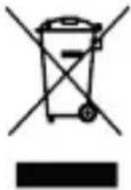
The symbol of the crossed-out wheeled bin means that this appliance must not be disposed of with household waste at the end of its useful life. The appliance must be disposed of in specially set-up collection points, recycling yards or disposal companies. Owners of WEEE from private households can hand them in free of charge at the designated collection points of the public waste disposal authorities or at the take-back points set up by manufacturers or distributors in terms of the Directive 2012/19/EU.
INDEX OF SYMBOLS
 | Refer to user manual |
 | Date of Manufacture |
 | Batch code |
 | Serial Number: indicates the manufacturer's serial number so that a specific medical device can be identified. |
 | Type BF equipment: providing a degree of protection against electric shock, with isolated applied part. Indicates that this device has conductive contact with the end user. |
 | The first number 2: Protected against access to hazardous parts with a finger, and the jointed test finger of 12mmø, 80mm length, shall have adequate clearance from hazardous parts, and protected against solid foreign objects of 12.5mmø and greater. The second number 2: Protected against vertically falling waterdrops when enclosure is tilted up to 15°. Vertically falling drops shall have no harmful effects when the enclosure is tilted at any angle up to 15° on either side of the vertical. |
 | Do not dispose in household waste. It is compliance with WEEE. |
 | CE symbol (conformity symbol) |
 | Manufacturer |
| UDI | Unique device identifier |
| MD | Medical device |
| EC REP | European Authorized Representative |
EMC PRECAUTIONS
Wireless communications equipment such as wireless home network devices, mobile phones, cordless telephones and their base stations, walkie-talkies can affect this equipment and should be kept at least a distance d = 3.3 m away from the equipment.
Note: as indicated in Table 6 of IEC 60601-1-2 for ME EQUIPMENT, a typical cell phone with a maximum output power of 2 W yields d = 3.3 m at an IMMUNITY LEVEL of 3 V/m.
1* WARNING: use of this equipment adjacent to or stacked with other equipment should be avoided because it could result in improper operation. If such use is necessary, this equipment and the other equipment should be observed to verify that they are operating normally.
2* WARNING: use of accessories, transducers and cables other than those specified or provided by the manufacturer of this equipment could result in increased electromagnetic emissions or decreased electromagnetic immunity of this equipment and result in improper operation.
3* WARNING: portable RF communications equipment (including peripherals such as antenna cables and external antennas) should be used no closer than 30 cm (12 inches) to any part of the ME equipment, including cables specified by the manufacturer. Otherwise, could result in degradation of the performance of this equipment.
Table 2: Declaration of Electromagnetic Emission
| Guidance and manufacturer's declaration – electromagnetic emissions | ||
| All models are intended for use in the electromagnetic environment specified below. The customer or the user of all models should assure that it used in such an environment. | ||
| Emissions Test Compliance Electromagnetic environment – guidance | ||
| RF emissions CISPR 11 Group 1 | All models use RF energy only for their internal function. Therefore, their RF emissions are very low and are not likely to cause any interference in nearby electronic equipment. | |
| RF emissions CISPR 11 Class B | All models are suitable for used in all establishments and those directly connected to the public low-voltage power supply network that supplies buildings used for domestic purposes. | |
| Harmonic emissions IEC 61000-3-2 | N/A | |
| Voltage fluctuations/flicker emissions IEC 61000-3-3 | N/A | |
Table 3: Declaration of Electromagnetic Immunity
| Guidance & Declaration – electromagnetic immunity | |||
| All models are intended for use in the electromagnetic environment specified below. The customer or the user of all modes should assure that they are used in such an environment. | |||
| Immunity Test | IEC 60601 Test Level | Compliance Level | Electromagnetic environment – guidance |
| Electrostatic discharge (ESD) IEC 61000-4-2 | ±8 kV contact ±2 kV, ±4 kV, ±8 kV, ±15 kV air | ±8 kV contact ±2 kV, ±4 kV, ±8 kV, ±15 kV air | Floors should be wood, concrete or ceramic tile. If floors are covered with synthetic material, the relative humidity should be at least 30 %. |
| Electrical fast transient/ burst IEC 61000-4-4 | N/A N/A None | ||
| Surge IEC 61000-4-5 N/A N/A None | |||
| Voltage dips, short interruptions and voltage variations on power supply input lines IEC 61000-4-11 | N/A N/A None | ||
| Power frequency (50/60 Hz) magnetic field IEC 61000-4-8 | 30 A/m N/A N/A | ||
| Proximity magnetic fields | CW 8 A/m for 30 KHz Pulse modulation 2.1KHz, 65 A/m for 134.2 KHz Pulse modulation 50 KHz, 7.5 A/m for 13.56 MHz | N/A N/A | |
Note: UT is the a.c. mains voltage prior to application of the test level.
Table 4: Declaration of Electromagnetic Immunity
| Guidance & Declaration – electromagnetic immunity | |||
| All models are intended for use in the electromagnetic environment specified below. The customer or the user of all models should assure that they are used in such an environment. | |||
| Immunity Test | IEC 60601 Test Level | Compliance Level | Electromagnetic environment – guidance |
| Conducted RF IEC 61000-4-6 | 3 Vrms150 kHz to 80 MHz6 Vrms in ISM bands and amateur radio bands (Only apply to patient coupling port) | 3 Vrms150 kHz to 80 MHz6 Vrms in ISM bands and amateur radio bands (Only apply to patient coupling port) | Portable RF communications equipment (including peripherals such as antenna cables and external antennas) should be used no closer than 30 cm (12 inches) to any part of all models, including cables specified by the manufacturer. Otherwise, degradation of the performance of this equipment could result. |
| Radiated RF IEC 61000-4-3 | 0 V/m80 MHz to 2.7 GHz385 MHz-5785 MHzTest specifications for ENCLOSURE PORT IMMUNITY to RF wireless communication equipment (Refer to table 9 of IEC 60601-1-2:2014+A1:2020) | 10 V/m80 MHz to 2.7 GHz385 MHz-5785 MHzTest specifications for ENCLOSURE PORT IMMUNITY to RF wireless communication equipment (Refer to table 9 of IEC 60601-1-2:2014+A1:2020) | |
STANDARDS CONFORMITY
The device is tested and complies with the international standards listed below:
| Standard Number Standard Title | |
| EN/IEC 60601-1 | Medical electrical equipment – Part 1: General requirements for basic safety and essential performance |
| EN/IEC 60601-1-2 | Medical electrical equipment – Part 1-2: General requirements for basic safety and essential performance – Collateral Standard: Electromagnetic disturbances – Requirements and tests |
| EN/IEC 60601-1-11 | Medical electrical equipment – Part 1-11: General requirements for basic safety and essential performance – Collateral Standard: Requirements for medical electrical equipment and medical electrical systems used in the home healthcare environment |
| EN/IEC 60601-2-10 | Medical electrical equipment – Part 2-10: Particular requirements for the basic safety and essential performance of nerve and muscle stimulators |
| EN ISO10993-1 | Biological evaluation of medical devices – Part 1: Evaluation and testing within a risk management process |
| EN ISO10993-5 Biological evaluation of medical devices. Tests for in vitro cytotoxicity | |
| EN ISO10993-10 Biological evaluation of medical devices – Part 10: Tests for skin sensitization | |
| EN ISO10993-23 Biological evaluation of medical devices – Part 23: Tests for irritation | |
| ISO 15223-1 | Medical devices – Symbols to be used with information to be supplied by the manufacturer – Part 1: General requirements |
DECLARATION OF CONFORMITY
Luvion declares that the medical equipment type Luvion® Pelvic Floor Trainer meets the provisions of REGULATION (EU) 2017/745 which apply to it. The medical device has been assigned to class IIa according to Annex IV of the REGULATION (EU) 2017/745. The product concerned has been designed and manufactured under a quality management system according to Annex IX, of REGULATION (EU) 2017/74. This EU declaration of conformity is issued under the sole responsibility of the manufacturer. No “Common Specification” is applicable.
The full text of the EU declaration of conformity is available at:
www.luvion.com/DOC/Pelvic-Floor-Trainer

EASYMED INSTRUMENTS CO., LTD. (SRN: CN-MF-000008905)
3/F-6/F, Block A, No.4, Fengxin Road, Fengxiang Industrial District,
Daliang, Shunde, Foshan 528300 Guangdong, P.R. China
EGERIUM BV
Kleveringweg 7, 2616 LZ Delft
The Netherlands

0197
INTRODUCTIE
OVERZICHT VAN DE STIMULATORUNIT

LET OP:
Bovenarm (Programma P15)
Dijen (Programma P16)
Heup (Programma P17)
3/F-6/F, Block A, No.4, Fengxin Road, Fengxiang Industrial District, Daliang, Shunde, Foshan 528300 Guangdong, P.R. China
INTRODUCTION
VUE D'ENSEMBLE DE L'UNITÉ DE STIMULATION
VUE D'ENSEMBLE DE L'AFFICHAGE À L'ÉCRAN
ATTENTION :
Cuisses (Programme P16)
Hanches (Programme P17)
CONFORMITÉ AUX NORMES
DÉCLARATION DE CONFORMITÉ
3/F-6/F, Block A, No.4, Fengxin Road, Fengxiang Industrial District, Daliang, Shunde, Foshan 528300 Guangdong, P.R. China
EGERIUM BV
Kleveringweg 7, 2616 LZ Delft
The Netherlands
EINLEITUNG


VORSICHT:
Oberarm (Programm P15)
3/F-6/F, Block A, No.4, Fengxin Road, Fengxiang Industrial District,
Daliang, Shunde, Foshan 528300 Guangdong, P.R. China
EGERIUM BV
Kleveringweg 7, 2616 LZ Delft
The Netherlands


0197
CE0197
I-LUVION-ML REV1.0 0725
EGERIUM BV
Kleveringweg 7
2616 LZ Delft
the Netherlands

Mdi Europa GmbH
Langenhagener Str. 71, 30855
Langenhagen, Germany
WWW.LUVION.COM



- PACKAGE CONTENTS
- OVERVIEW OF THE STIMULATOR UNIT
- OVERVIEW OF THE SCREEN DISPLAY
- SAFETY INSTRUCTIONS
- CONTRAINDICATION
- WARNING
- PRECAUTIONS
- ADVERSE REACTIONS
- GENERAL WARNINGS AND INSTRUCTION FOR DEVICE
- MAINTENANCE
- HOW TO USE
- STEP 1: INSERT THE BATTERIES
- CAUTION
- STEP 2: CONNECT THE WIRES
- STEP 3: APPLY THE ACCESSORY
- PELVIC FLOOR TRAINING USING THE VAGINAL PROBE
- MUSCLE RECOVERY USING THE ELECTRODE PADS
- ELECTRODE PADS PLACEMENT
- STEP 4: POWER ON THE DEVICE
- TURN ON/OFF
- SELECTING A PROGRAM
- ADJUSTING INTENSITY
- PAUSE AND RESUME
- SESSION DURATION AND AUTOMATIC SHUT-OFF
- OTHER FEATURES
- RECOMMENDED USE
- OTHER APPROVED USES
- APPLICABLE AREAS
- CLEANING INSTRUCTIONS
- DO NOT
- SERVICE AND MAINTENANCE
- REPLACEMENT
- CAUTIONS
- TROUBLESHOOTING
- TECHNICAL SPECIFICATIONS
- GUARANTEE
- DISPOSAL OF WASTE ELECTRICAL AND ELECTRONIC PRODUCTS (WEEE)
- INDEX OF SYMBOLS
- EMC PRECAUTIONS
- STANDARDS CONFORMITY
- DECLARATION OF CONFORMITY
- INTRODUCTIE
- OVERZICHT VAN DE STIMULATORUNIT
- LET OP
- INTRODUCTION
- VUE D'ENSEMBLE DE L'UNITÉ DE STIMULATION
- VUE D'ENSEMBLE DE L'AFFICHAGE À L'ÉCRAN
- ATTENTION
- CONFORMITÉ AUX NORMES
- DÉCLARATION DE CONFORMITÉ
- EGERIUM BV
- EINLEITUNG
- VORSICHT
Brand : Luvion
Model : Pelvic Floor Trainer
Category : Medical device