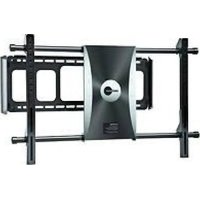
POWER 55 - Motorized wall mount for TV OmniMount - Free user manual and instructions
Find the device manual for free POWER 55 OmniMount in PDF.


| Product Type | Motorized TV Wall Mount |
| Brand | OmniMount |
| Model | POWER 55 |
| Maximum Weight Capacity | 110 lb (50 kg) |
| Maximum Screen Size | 55 inches (140 cm) |
| Power Supply | AC adapter (100-240 V AC, 50/60 Hz) |
| Main Functions | Motorized rotation, motorized tilt, 2 memory positions, wall detection, IR remote control |
| VESA Compatibility | Up to 400x400 mm (see manual) |
| Package Contents | Wall mount, adapter plate, IR receiver, remote control, screws, manual tools required |
| Warranty | 1 year (defects in materials and workmanship) |
| Safety | Do not exceed maximum load; installation by qualified installer; verify wall capacity |
| Maintenance and Cleaning | Clean with a soft, dry cloth; do not use abrasive products |
| Spare Parts and Repairability | Contact OmniMount customer service for spare parts |
| General Information | Indoor use only; do not use with a CRT TV |
Frequently Asked Questions - POWER 55 OmniMount
User questions about POWER 55 OmniMount
0 question about this device. Answer the ones you know or ask your own.
Ask a new question about this device
Download the instructions for your Motorized wall mount for TV in PDF format for free! Find your manual POWER 55 - OmniMount and take your electronic device back in hand. On this page are published all the documents necessary for the use of your device. POWER 55 by OmniMount.
USER MANUAL POWER 55 OmniMount
Instruction Manual EN
natural_image
Exterior view of a black CD or DVD unit mounted on a metal frame structure (no visible text or symbols)Maximum screen size: 55"
Maximum weight 110 lbs - 50 KG
CAUTION: DO NOT EXCEED MAXIMUM LISTED
WEIGHT CAPACITY. SERIOUS INJURY OR PROPERTY
DAMAGE MAY OCCUR!
Images may differ from actual productEN
■ WARNING! SEVERE PERSONAL INJURY AND PROPERTY DAMAGE CAN RESULT FROM IMPROPER INSTALLATION OR ASSEMBLY. READ THE FOLLOWING WARNINGS BEFORE BEGINNING.
- If you do not understand the instructions or have any concerns or questions, please contact a qualified installer. North America residents can contact OmniMount customer service at 800.668.6848 or info@omnimount.com.
- Do not install or assemble if the product or hardware is damaged or missing. If you require replacement parts, contact OmniMount Customer Service at 800.668.6848 or Info@omnimount.com. International customers need to contact a local distributor for assistance.
- For wall mounted products: This product has been designed for use on a vertical wall constructed of wood studs or masonry (solid concrete). Wood studs being defined as a wall consisting of a minimum of 2 x 4 inch studs with a maximum of 24 inch stud spacing and a minimum of 16 inch stud spacing with a maximum of 34 inch of wall covering (drywall, lath, plaster). If you don't know your wall type, or for assistance with other surfaces (metal studs, solid block and brick), contact a qualified installer. For safe installation, the wall you are mounting to must support 4 times the weight of the total load. If not, the surface must be reinforced to meet this standard. The installer is responsible for verifying that the wall structure/surface and the anchors used in the installation will safely support the total load.
This product is not designed to support the load of a CRT or flat screen television. Do not use this product for any application other than those specified by OmniMount.
■ This product may contain moving parts. Use with caution.
- DO NOT EXCEED THE MAXIMUM WEIGHT CAPACITY FOR THIS PRODUCT.

| Contents - POWER 55 | |||
| Pouch # | Part # | Qty | Description |
| 11 | Wall Mount | ||
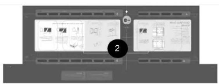
| 12 | Wall Template | ||
| Instruction Manual13 | |||
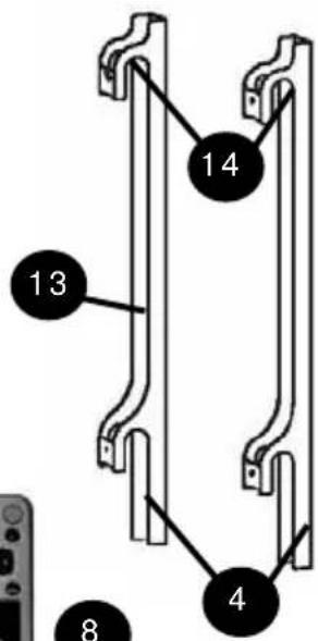
| Vertical Rails24 | |||
| Horizontal Rails (485mm End Cap to End Cap)25 | |||
| End Caps & Screws46 | |||
| Power Adapter17 | |||
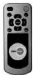
| Remote Control18 | |||
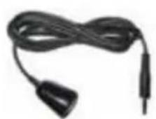
| IR Receiver19 | |||
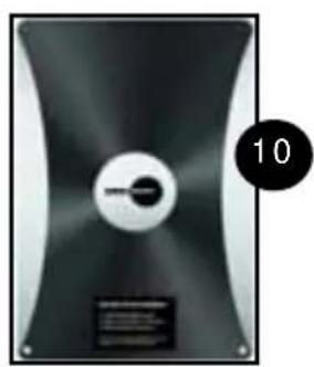
| Mylar Sticker110 | |||
| Tension Screws (Pre Installed) M6 x 7mm211 | |||
| Horizontal Rail Screws (Pre Installed)412 | |||
| Vertical Rail Covers (Pre Installed)213 | |||
| Vertical Rails Plastic J Clips (Pre Installed)814 | |||
natural_image
Black and white photo of a CD-ROM drive with a keyhole and label (no readable text or symbols)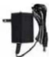
7
9
CONTENTS
Monitor Kit - POWER 55
| DescriptionQtyPart #Pouch # | |||
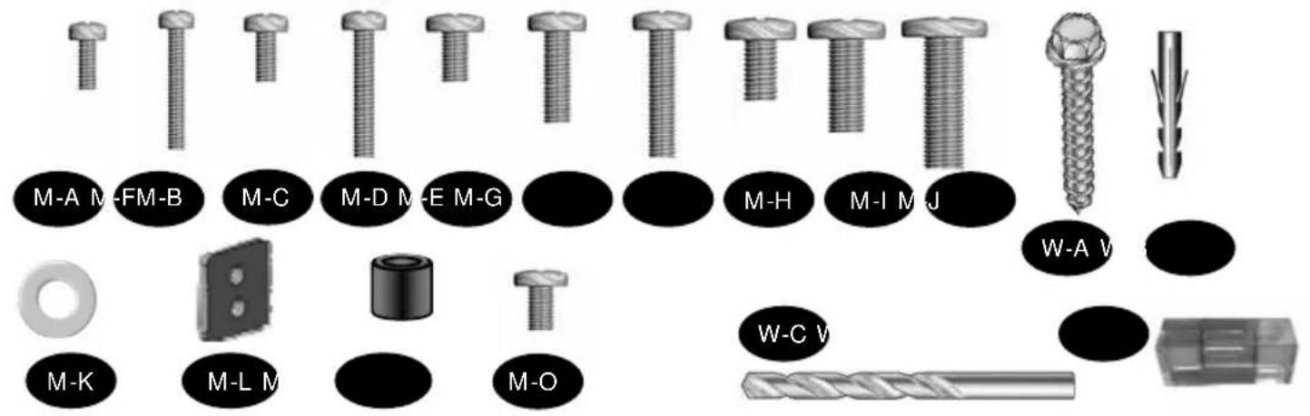
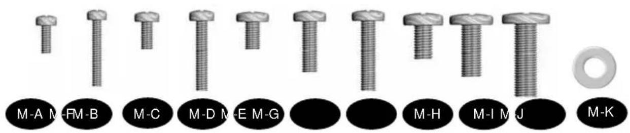
| M-A | M-A | 4 | Philips screws M4 x 15mm |
| M-B | M-B | 4 | Philips screws M4 x 45mm |
| M-C | M-C | 4 | Philips screws M5 x 15mm |
| M-D | M-D | 4 | Philips screws M5 x 45mm |
| M-E | M-E | 4 | Philips screws M6 x 15mm |
| M-F | M-F | 4 | Philips screws M6 X 20mm |
| M-G | M-G | 4 | Philips screws M6 x 45mm |
| M-H | M-H | 4 | Philips screws M8 x 15mm |
| M-I | M-I | 4 | Philips screws M8 x 29mm |
| M-J | M-J | 4 | Philips screws M8 x 45mm |
| M-K | M-K | 4 | Washer OD 10mm ID 5mm x 1.0mm |
| M-L | M-L | 4 | Square Washers |
| M-M | M-M | 4 | Circular Spacers: 19.5mm OD x 8.25mm ID x 14.5mm H |
| M-N | M-N | 3 | Wire Holders (Zip Ties) |
| M-O | M-O | 2 | Philips screws M5 X 12 mm (Locking Screws) |
| Wall Kit - POWER 55 | |||
| DescriptionQtyPart #Pouch # | |||
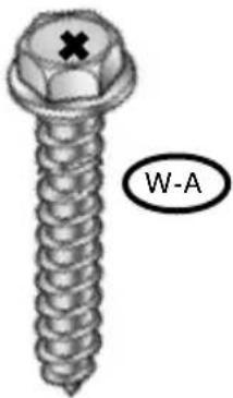
| W-A | W-A | 6 | Wall Phillips Hex Screw M6 x 50mm |
| W-B | W-B | 6 | Wall Anchors M6 |
| W-C | W-C | 1 | Wood Drill Bit 1/8" |
| W-D | W-D | 1 | Bubble Level |
Wall Kit - POWER 55
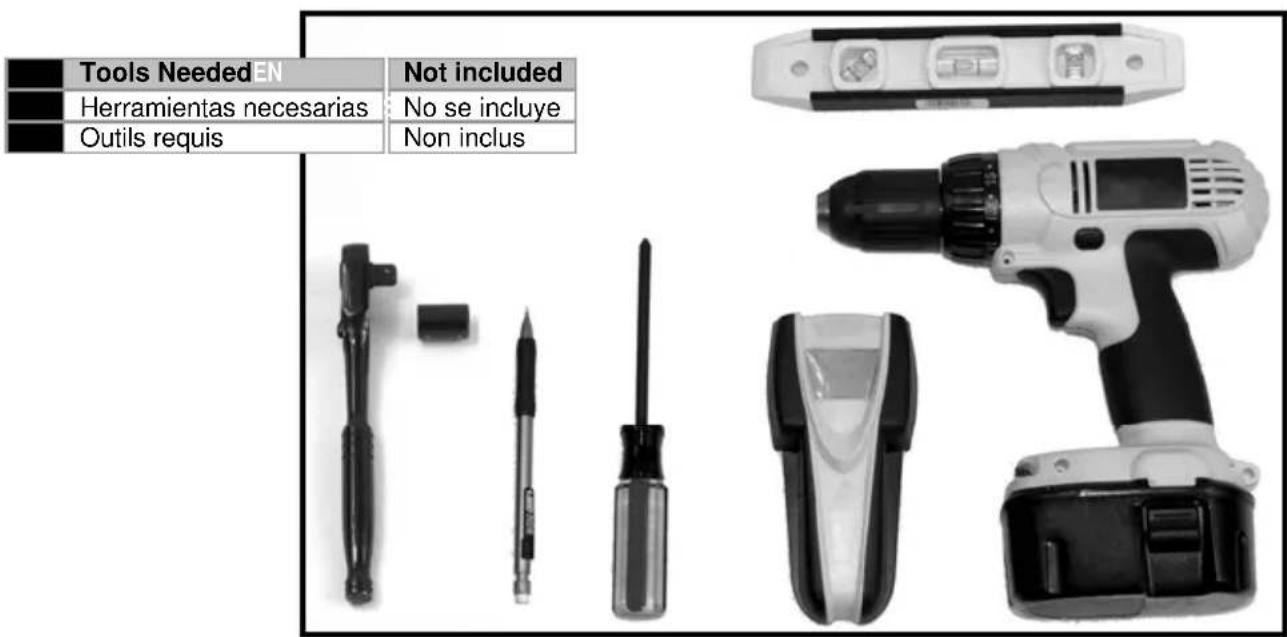
TOOLS NEEDED
natural_image
Black and white icon of a drill bit inside a circle (no text or symbols)| EN | Drill |
| ES | Agujerear |
| FR | Percer |
natural_image
Simple black-and-white icon of a hammer inside a circle (no text or symbols)| EN | Hammer |
| ES | Martillo |
| FR | Marteau |

| EN | Optional |
| ES | Opcional |
| FR | Optionnel |

natural_image
Simple black 'X' symbol inside a circle, no text or additional markings| EN | Remove |
| ES | Retire |
| FR | Retirez |
natural_image
Circular diagram with four arrows pointing outward from a central circle (no text or symbols)| EN | Adjust |
| ES | Ajuste |
| FR | Ajustez |
natural_image
Simple line drawing of a light bulb inside a circle (no text or symbols)| EN | Cable Management |
| ES | Sistema de organización de cables |
| FR | Gestion des câbles |
natural_image
Simple line drawing of a pencil inside a circle (no text or symbols)natural_image
Simple line drawing of a hand holding an object, enclosed in a circle (no text or symbols)natural_image
Simple line drawing of a right-angle pipe with a circular base and a small circular mark (no text or symbols)| EN | Allen Wrench |
| ES | Llave Allen |
| FR | Clé hexagonale |
natural_image
Simple circular target with concentric rings and crosshairs (no text or symbols)natural_image
Simple line drawing of a syringe inside a circle (no text or symbols)| EN | Phillips Screwdriver |
| ES | Destornillador Phillips |
| FR | Tournevis Phillips |

| EN | Caution |
| ES | Precaución |
| FR | Attention |
natural_image
Simple circular diagram with three vertical oval elements inside, no text or symbols present.| EN | Level |
| ES | Nivel |
| FR | Niveau |
| EN | Tighten Fastener |
| ES | Ajuste el sujetador |
| FR | Serrez l'attache |
| EN | Loosen Fastener |
| ES | Afloje el sujetador |
| FR | Desserrez l'attache |
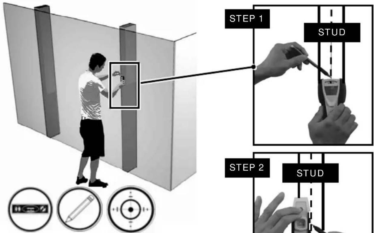
WOOD STUD INSTALLATION
flowchart
graph TD
    A["STEP 1"] --> B["STUD"]
    B --> C["STEP 2"]
    C --> D["STUD"]
    style A fill:#f9f,stroke:#333
    style B fill:#ccf,stroke:#333
    style C fill:#cfc,stroke:#333
    style D fill:#fcc,stroke:#333
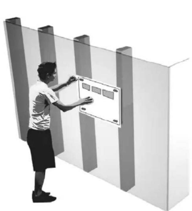
EN Find stud(s) and mark edge and center locations.
CAUTION: Any Wood Stud Installation Greater than 16" Wide Must use a Dry Wall Anchor (Not Included) in the (B-Left) Section of the Wall Template.
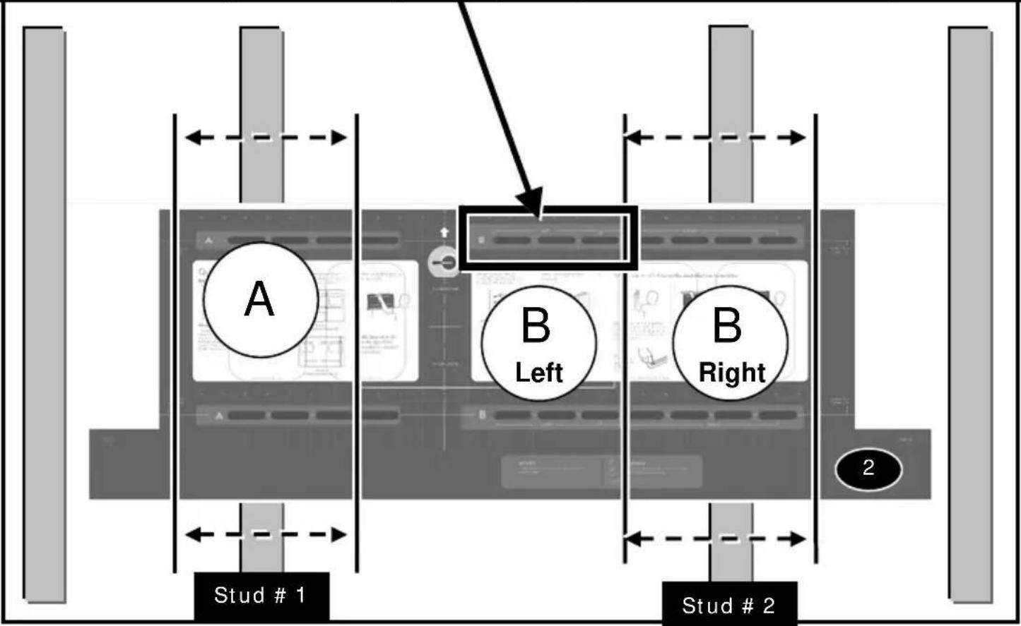
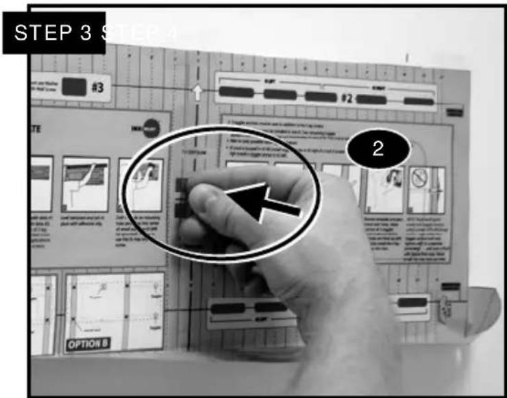
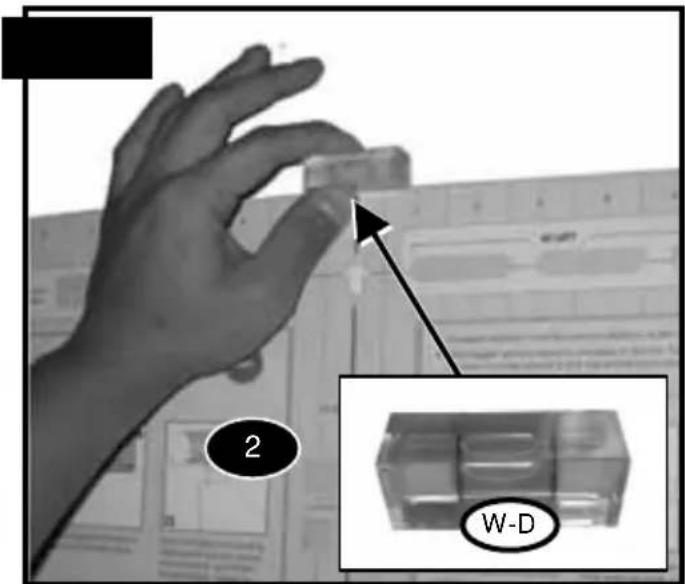
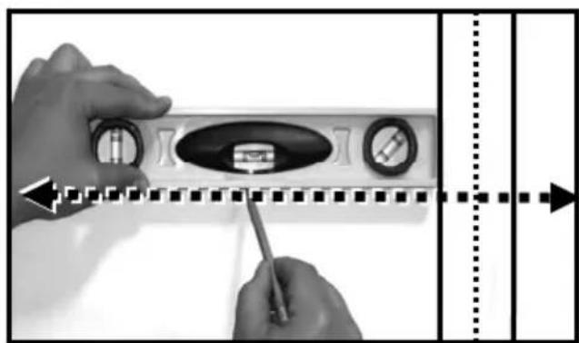
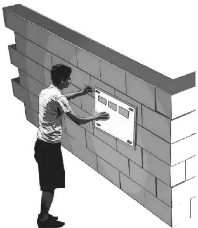
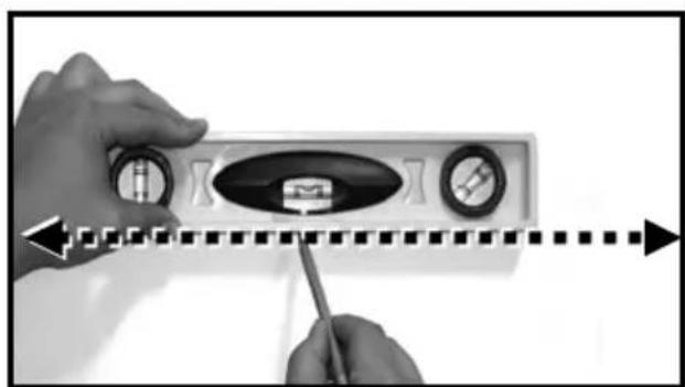
Follow directions on the mounting template and use Bubble Level (W-D), secure to wall. Locate the middle mark of the Wall Template, use a Pin (not included) to secure the template into place.
natural_image
Person interacting with a wall-mounted control panel (no visible text or symbols)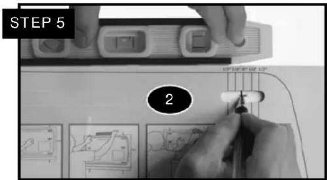
natural_image
Circular target with concentric rings and crosshairs (no text or symbols)
natural_image
Simple line drawing of a pencil inside a circle (no text or symbols)
natural_image
Simple circular diagram with a horizontal bar and three internal symbols (no text or labels)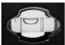
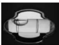
Good No Good
natural_image
Black-and-white illustration of a person using a power tool on a wall, with warning symbols and target icons below (no text or labels)STEP 6
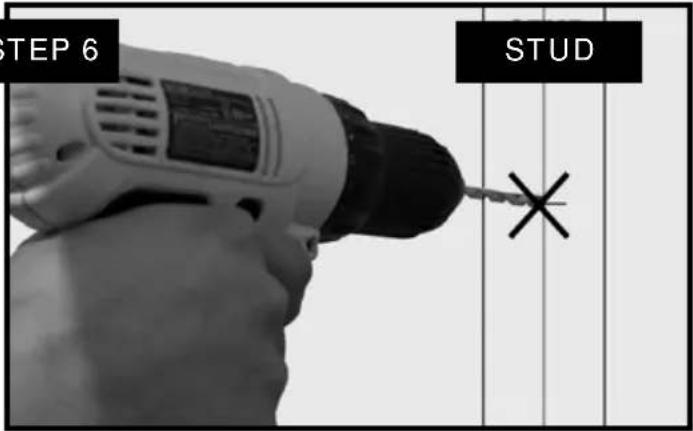
Wood Pilot
Pilot Hole Size Pilot Drill Depth
1/8" inch 2 inch
4 mm 55 mm

W-C

Drill pilot holeEN
Stud
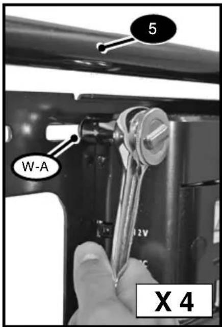
X 4
natural_image
Illustration of a hexagonal bolt with a cross mark on its head, labeled 'W-A' (no other text or symbols)Tighten Fasteners
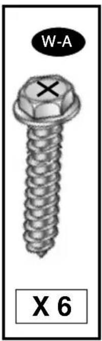
Place Wall Template (2) on solid concrete wall. A total of 6 Wall Anchors (W-B) and 6 Wall Screws (W-A) must be installed. Refer to Wall Template (2) for further instructions.
Two Wall Anchors (W-B), Screws (W-A) must be installed in Section (A). Two Wall Anchors (W-B), Screws (W-A) must be installed in Section (B Left). Two Wall Anchors (W-B), Screws (W-A) must be installed in Section (B Right).

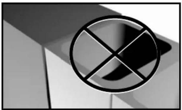
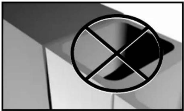
Solid Concrete Only Do Not Drill Into Mortar
natural_image
Symbol of a crossed-out circle with diagonal lines, resembling a prohibition sign (no text or numbers present)
Solid Concrete Only Do Not Drill Into Mortar
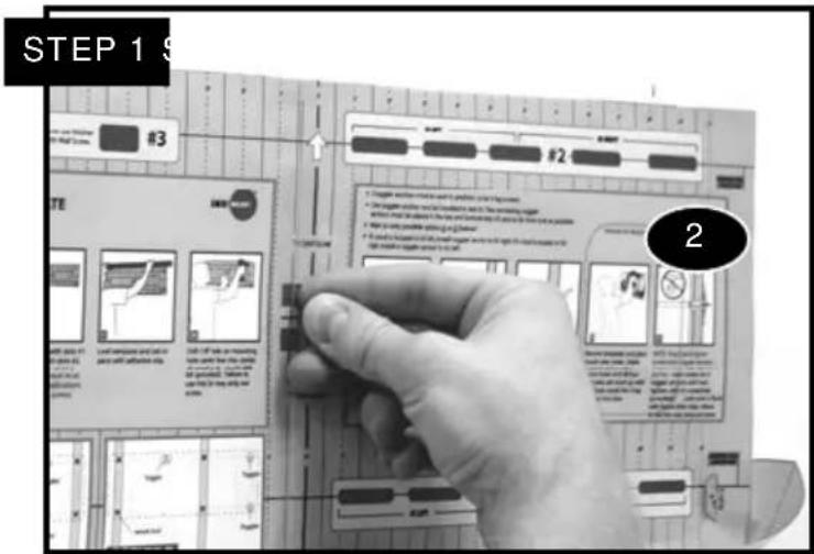
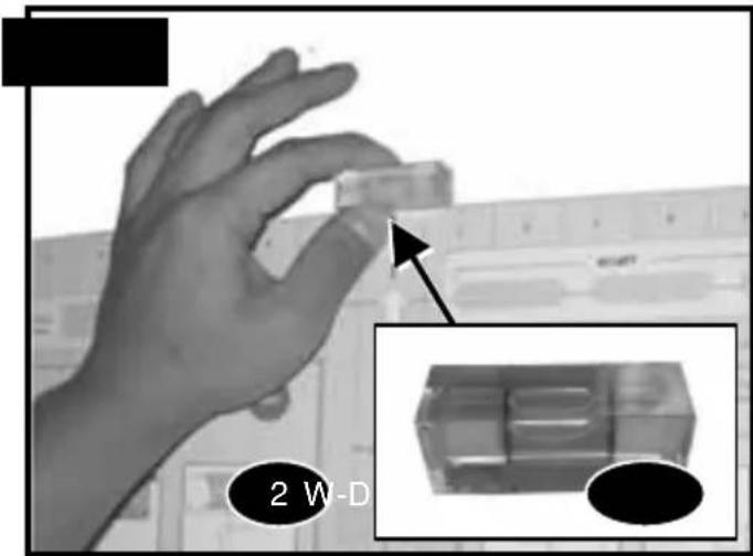
Follow directions on the mounting template and use Bubble Level (W-D), secure to wall. Locate the middle mark of the Wall Template.
natural_image
Person installing a wall-mounted panel on a brick wall (no text or symbols visible)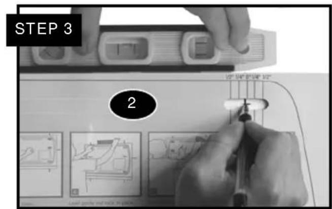
natural_image
Close-up of hands adjusting a wall-mounted dial indicator with a pointer (no text or symbols visible)
natural_image
Three circular icons: target, pencil, and electrical switch symbol (no text or labels)
natural_image
Two identical grayscale images of a stylized object with rounded corners, shown from different angles (no text or symbols)Good No Good
Use wall template to mark mounting locationsEN
For solid concrete wall installation 6 screws and anchors are required.

natural_image
Illustration of a person inspecting a brick wall with a tool (no text or symbols visible)
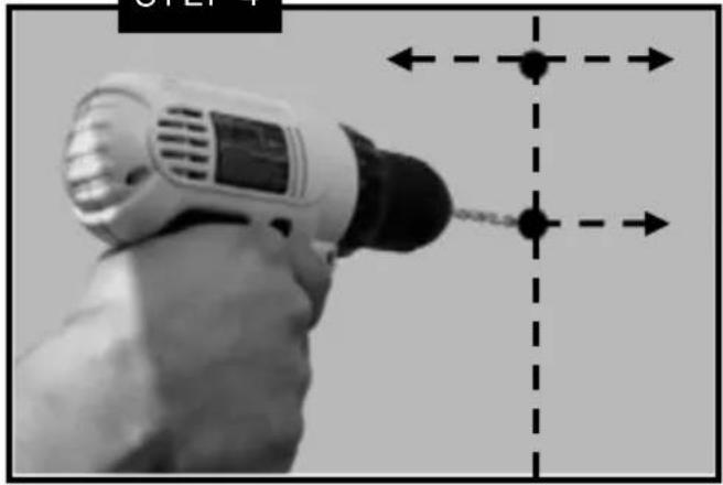
STEP 4
natural_image
Hand holding a handheld electric drill with a black-and-white alignment guide (no text or symbols visible)Masonry Pilot
Pilot Hole Size Pilot Drill Length
5/16 inch 2 - 1/8" inch
8 mm 55 mm

Not Included
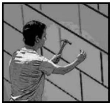
Masonry mounting must use a minimum of 6 lag screws and anchors
natural_image
Person using a hammer on a tiled wall (no text or symbols visible)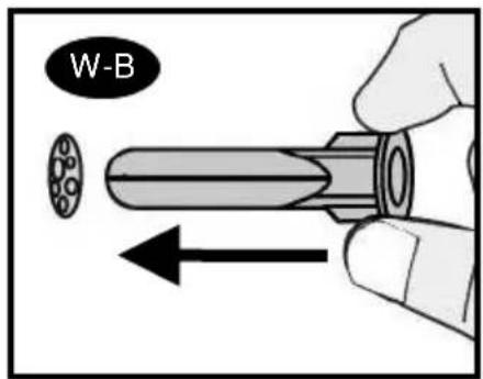
STEP 5
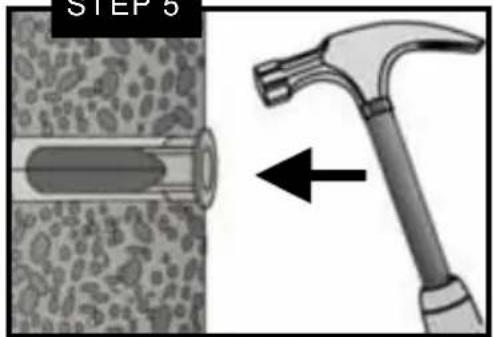
EN Concrete Wall Installation
Solid Concrete Only Do Not Drill Into Mortar
natural_image
Symbol of a crossed-out circle with diagonal lines, mounted on a 3D geometric background (no text or numbers)
Solid Concrete Only Do Not Drill Into Mortar
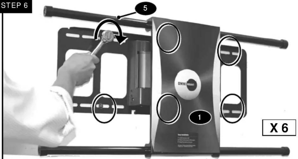
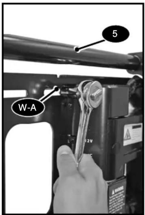
Before lifting mount into position ensure that all pilot holes are drilled and Anchors (W-B) necessary are installed. Assistance may be needed to hold mount in position while installing screws. NOTE: 6 wall screws and anchors are required in solid concrete wall installation.
natural_image
Three circular icons showing a hand holding a pen, a circular arrow indicating refresh, and a digital balance scale with three buttons (no text or symbols)| Tighten Fasteners | Hand tools only | |
| ES | Ajuste el sujetador | Herramientas de mano solamente |
| FR | Serrez l'attache | Outils manuels uniquement |
HAND TIGHTEN ONLY!
Failure to do this may result / damage of stripping the Anchors.
READ!!! SLIM TV (6 cm thickness or less only)
READ!!!!!! Mount comes adjusted factory default suitable to fit most TV's. This step is ONLY Slim Size Televisions with a depth of 0.24 in. (6 cm) or less. Check you TV installation Manual if your TV fits this criteria. You must adjust TV's in this size range in order for the mount to function properly. If your TV does not fit this criteria, Skip to Page 16.
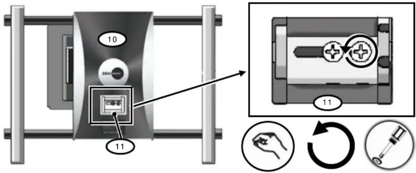
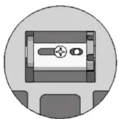
Remove perforated tabs to Access Tension Springs (11) on Front Monitor Plate. Remove the first screw to the right side of the Monitor Plate.
natural_image
Simple line drawing of a device inside a circular frame (no text or symbols)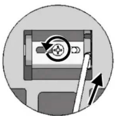
natural_image
Diagram of a device with a circular button and directional arrows, no readable text or symbols present.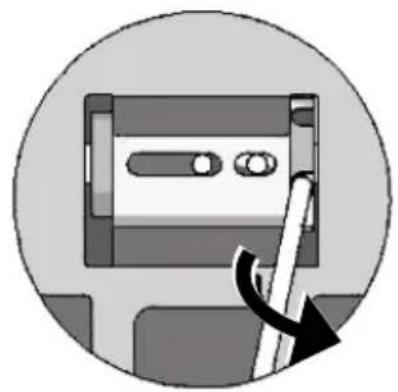
natural_image
Icon of a computer monitor with a scroll wheel, no text or symbols presentInsert screwdriver or solid rod into slot holes on Right, applying pressure (IMPORTANT!). Assistance Highly Recommended: While applying pressure carefully unscrew second screw.
SPRING TENSION IS HIGH. DO NOT LOOSE GRIP ON SCREWDRIVER / ROD!
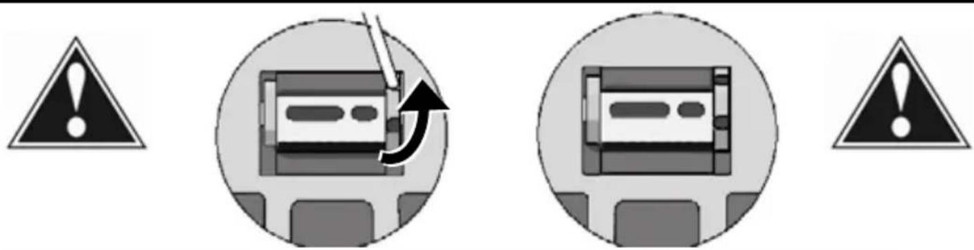
Once second screw is removed, slowly allow the tension spring to unwind upwards. Allow it uncoil until it rests. If in future a larger Monitor / TV are to be installed on Auto Wall Mount, Please Reverse Steps Above to adjust Tension to Springs.
flowchart
graph TD
    A["Light Lamp 1"] -->|100mm| B["Light Lamp 2"]
    B -->|200mm| C["Light Lamp 3"]
    C -->|200mm| D["Light Lamp 4"]
    D -->|200mm| E["Light Lamp 5"]
    E -->|200mm| F["Light Lamp 6"]
    F -->|200mm| G["Light Lamp 7"]
    G -->|200mm| H["Light Lamp 8"]
    H -->|200mm| I["Light Lamp 9"]
    I -->|200mm| J["Light Lamp 10"]
    J -->|200mm| K["Light Lamp 11"]
    K -->|200mm| L["Light Lamp 12"]
    L -->|200mm| M["Light Lamp 13"]
    M -->|200mm| N["Light Lamp 14"]
    N -->|200mm| O["Light Lamp 15"]
    O -->|200mm| P["Light Lamp 16"]
    P -->|200mm| Q["Light Lamp 17"]
    Q -->|200mm| R["Light Lamp 18"]
    R -->|200mm| S["Light Lamp 19"]
    S -->|200mm| T["Light Lamp 20"]
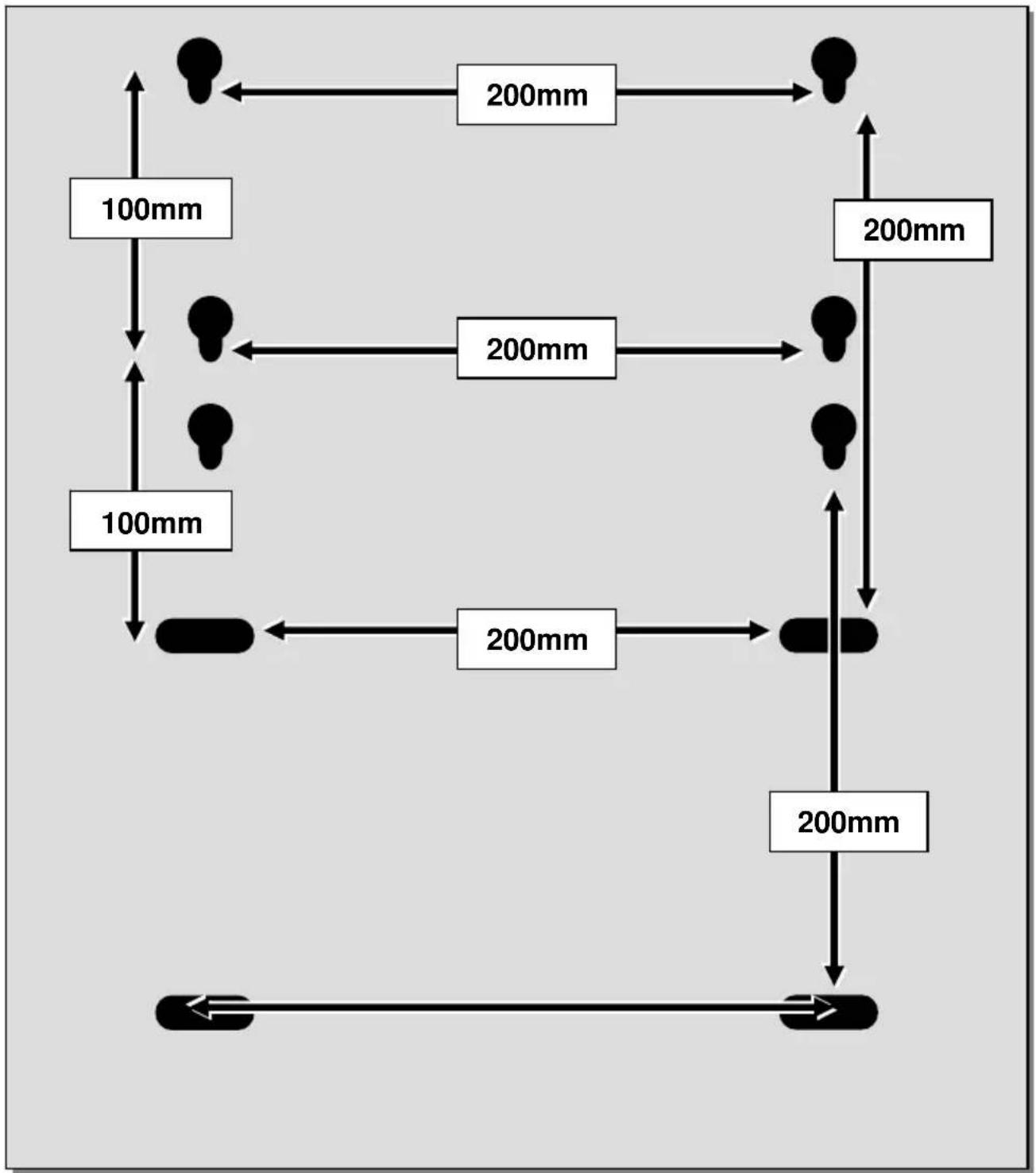
VESA
200mm x 200mm
100mm x 200 mm
Punch out perforated lines to access horizontal rail screws (12).

natural_image
Simple line drawing of a syringe inside a circle (no text or symbols)
natural_image
Simple line drawing of a hand holding an object, enclosed in a circle (no text or symbols)
natural_image
Simple black circular arrow symbol on white background (no text or labels)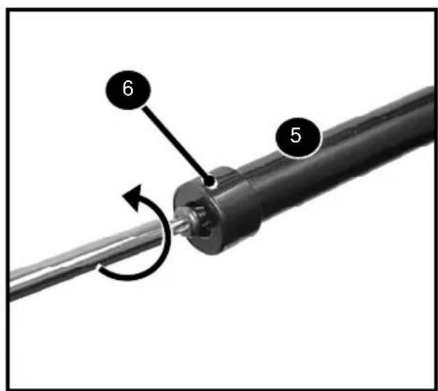
| Loosen Fastener EN | |
| ES | Afloje el sujetador |
| FR | Desserrez l'attache |
| RemoveEN | |
| ES | Retire |
| FR | Retirez |
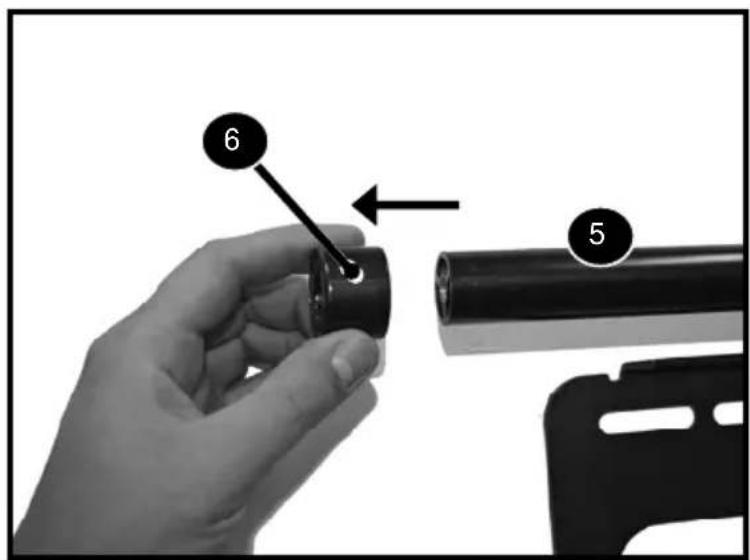
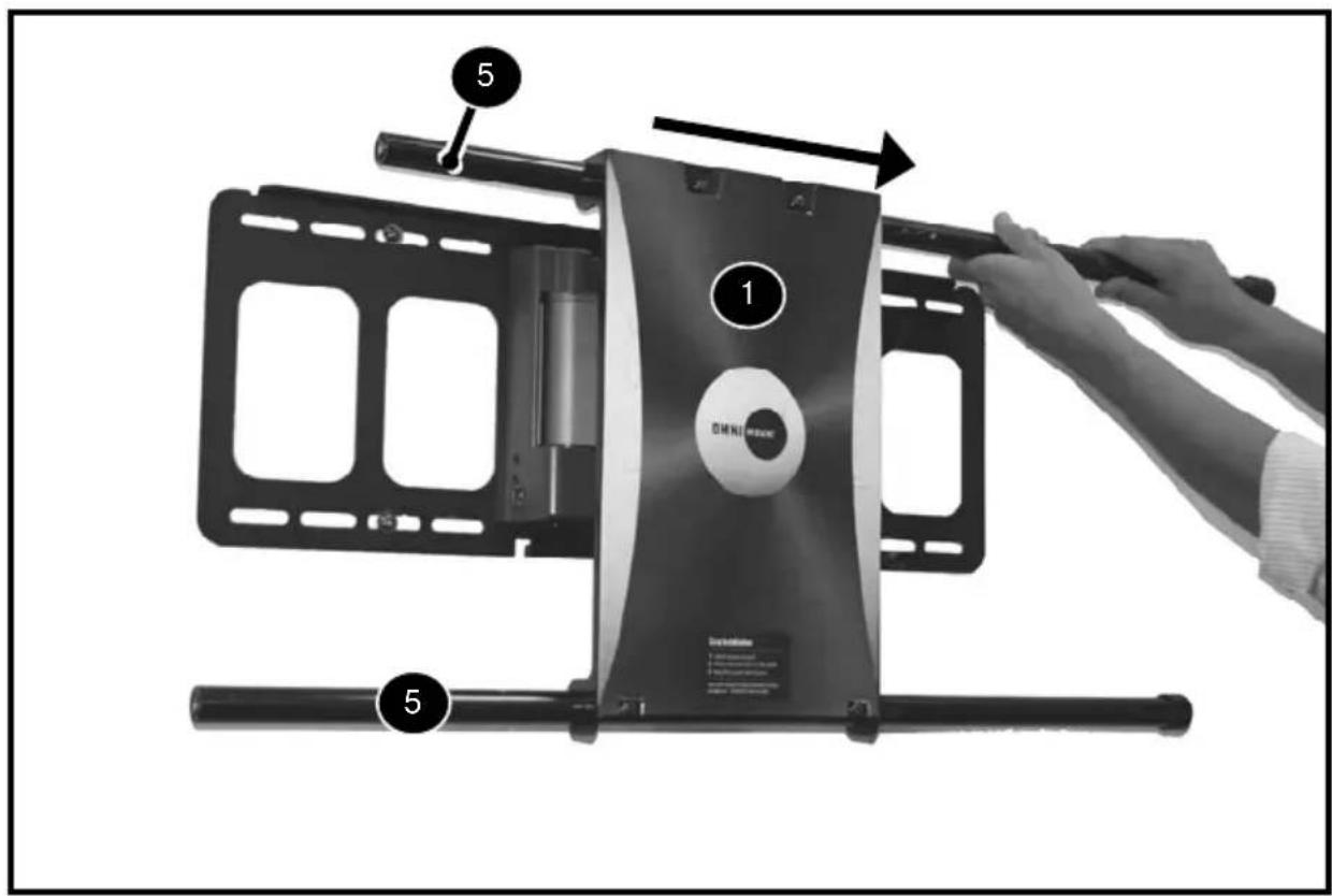
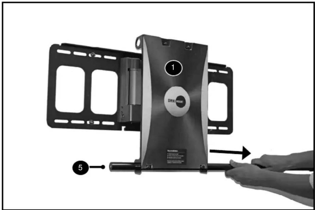
Remove the End Caps (6) from Horizontal Rails (5). The End Cap Sticker must be peeled back to access the screws. Discard End Cap Stickers.
| Remove | |
| ES | Retire |
| FR | Retirez |
| Remove | |
| ES | Retire |
| FR | Retirez |
VESA MONITOR INSTALLATION

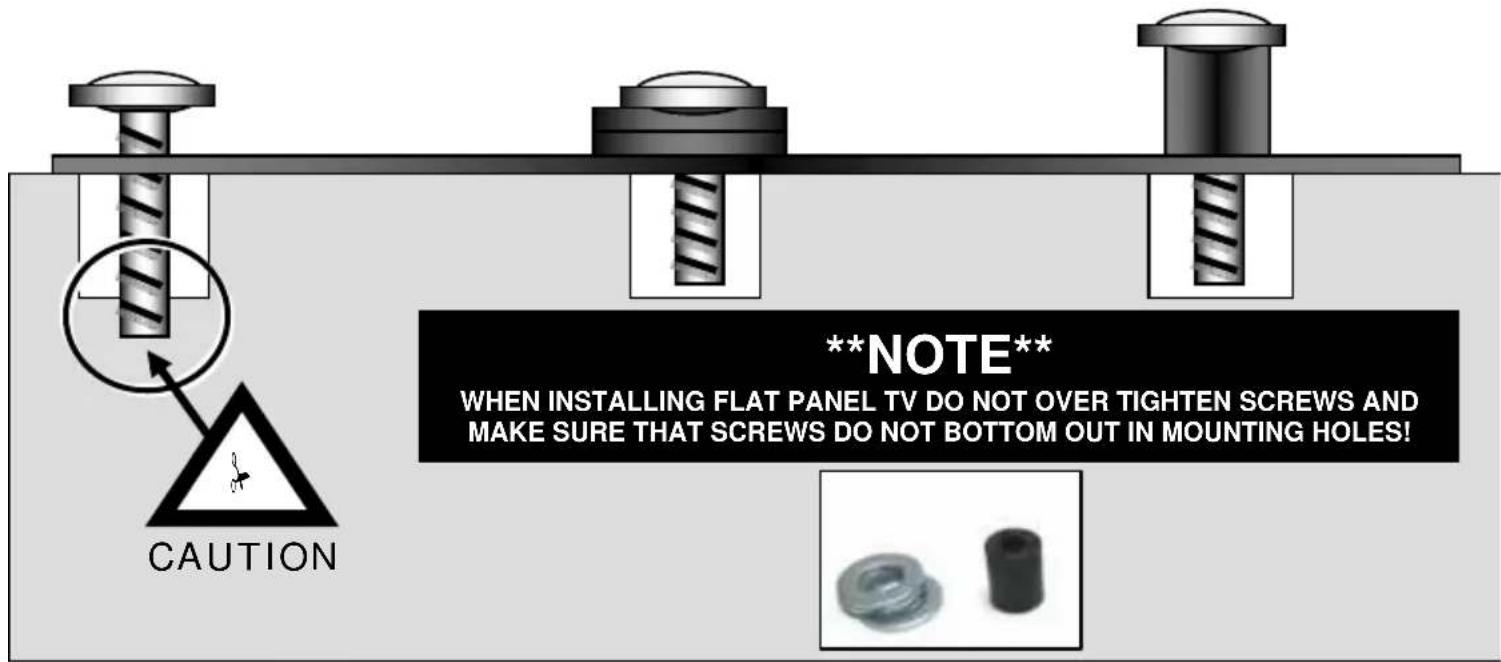
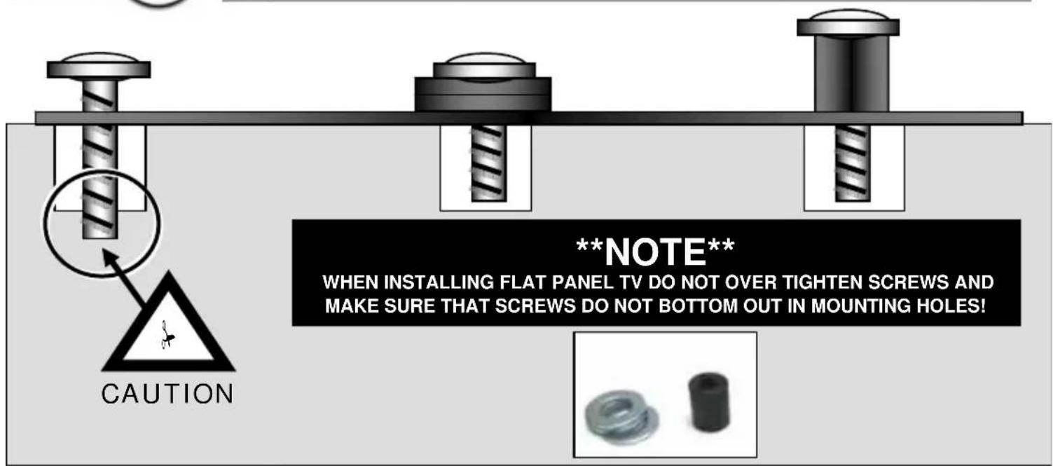
EN Attention: If screw "bottoms out" use washers (not included) to take up slack
ES Atención: Si el tornillo hace tope, utilice arandelas (no se incluyen) para ajustarlo al máximo.
FR Attention : Si les vis dépassent en dessous, utilisez des rondelles (non incluses) pour compenser
natural_image
Simple line drawing of a hand holding an object, enclosed in a circle (no text or symbols)
natural_image
Simple line drawing of a syringe inside a circle (no text or symbols)
natural_image
Illustration of a person using a power tool to cut a broken electronic device with warning symbols (no text or labels)| Partially installEN | |
| ES | Instalación parcial |
| FR | Installez partiellement |
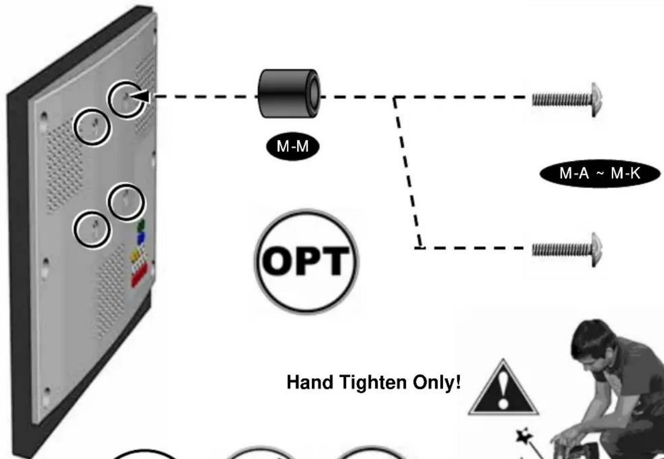
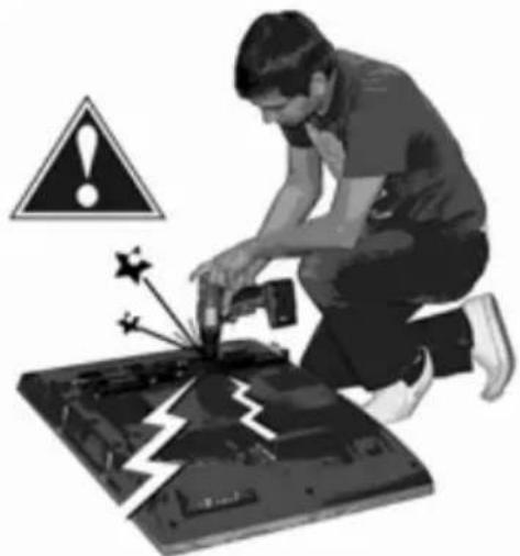
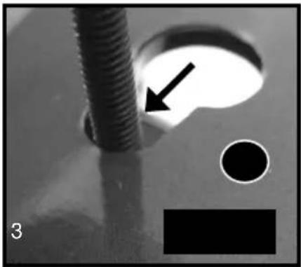
Partially install top two Philips screws (M-A \~ M-J). Please use Washers (M-K) for screw sizes M4 and M5 (M-A \~ MD).
Do Not Tighten
natural_image
Three circular icons: syringe, curved arrow, and hand gesture (no text or symbols)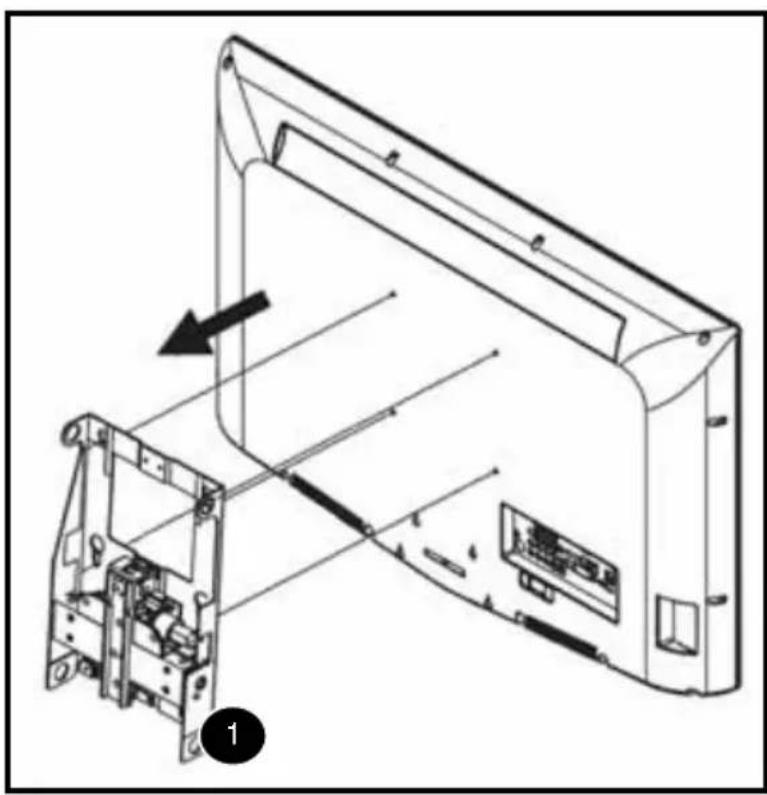
natural_image
Technical line drawing of a device's internal structure showing assembly and component alignment (no text or symbols)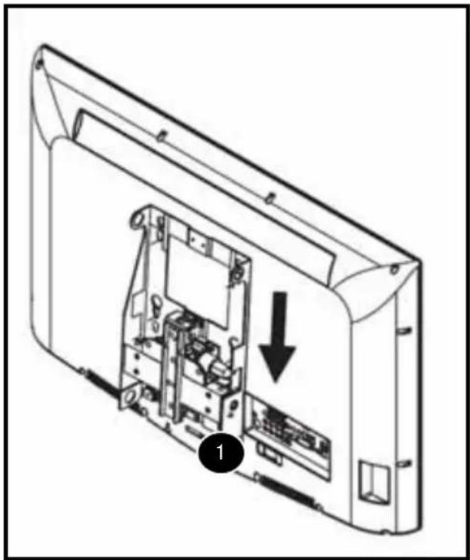
natural_image
Technical line drawing of an internal device casing with internal components and a downward arrow indicating a component (no text or symbols present)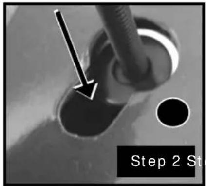
natural_image
Close-up of a threaded screw with an arrow pointing to a circular hole, alongside a black circle and a black rectangle (no text or symbols)Attach the TV to the Monitor Plate (1) with ONLY the top 2 screws partially installed through the Top 2 Keyhole Openings. Let Monitor Hang from the Top 2 Screws (Support Monitor Weight for safety while installing bottom 2 Screws), Secure the bottom 2 screws. M4 and M5 (M-A \~ MD) Screws Must use a Washer (M-K).
NON-VESA / LARGER MONITOR INSTALLATION

EN Attention: If screw "bottoms out" use washers (not included) to take up slack
ES Atención: Si el tornillo hace tope, utilice arandelas (no se incluyen) para ajustarlo al máximo.
FR Attention : Si les vis dépassent en dessous, utilisez des rondelles (non incluses) pour compenser
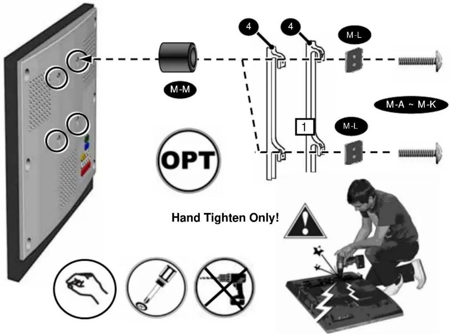
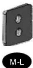
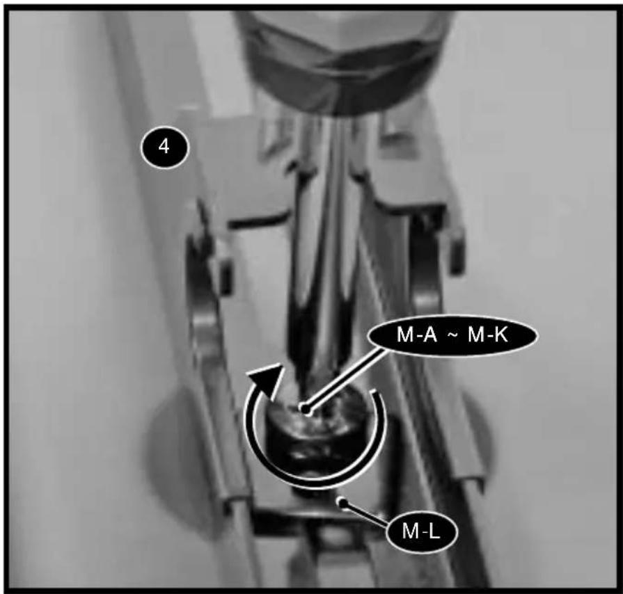
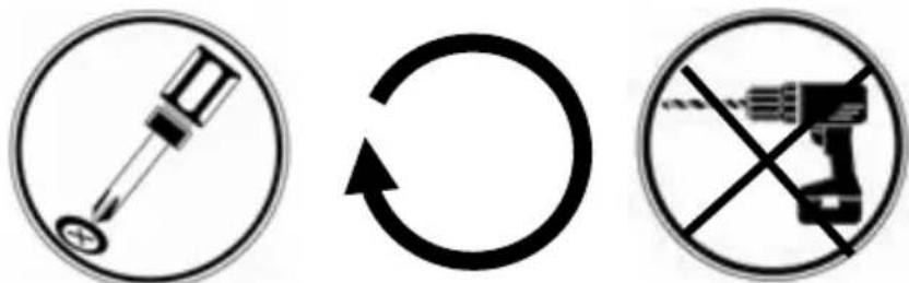
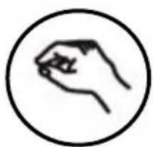
Insert Correct Size Screws (M-A \~ M-K) through the Square Washer (M-L) and Tighten into Television. HAND TIGHTEN ONLY.
Do not Over tighten.
Tighten all 4 Monitor Screws
| Attach coversEN | |
| ES | Coloque las cubiertas |
| FR | Fixez les caches |
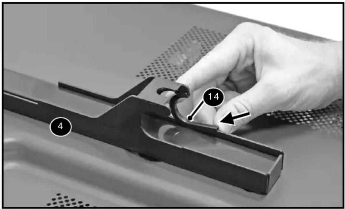
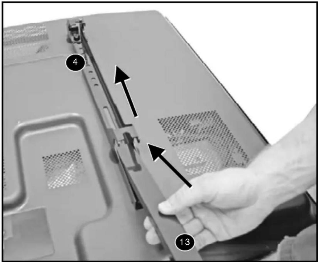
Install 8 Plastic J-Clips (14) vertical rails
Hang with monitor attached
Center Monitor / TV by carefully sliding the Monitor / TV Left or Right Use a Level to Make Sure the TV is Level When on the Horizontal Rails
This step may require two peopleEN
natural_image
Simple line drawing of a syringe inside a circle (no text or symbols)
natural_image
Simple black circular arrow symbol on white background (no text or labels)
natural_image
Prohibition sign with a diagonal line crossing a circle, indicating no text or symbols beyond the prohibition design.
Tighten Fastener
Ajuste el sujetador
Serrez l'attache
Tighten the Phillips screws (M-O) on the back of both the vertical rails. This will ensure that the television is secure.
IR RECEIVER
natural_image
Close-up of two hands holding a small electronic component, one with a pointed tip and the other a threaded plug (no text or symbols visible)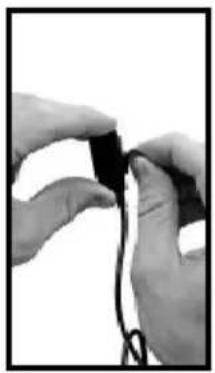
natural_image
Close-up of hands holding a small black object with a string, against a white background (no text or symbols visible)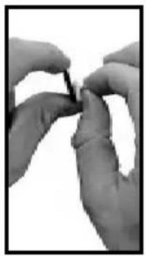
natural_image
Close-up of hands holding a small object, possibly a tool or component (no visible text or symbols)
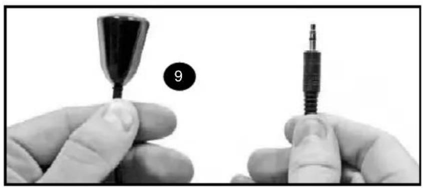
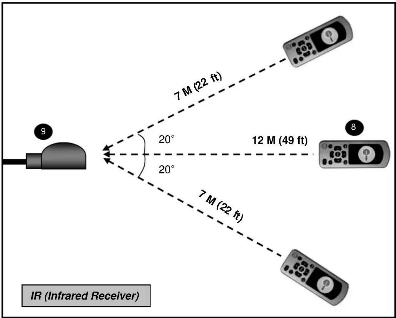
Separate the Velcro. Peel the Backing from the Velcro. Place the Velcro to desired location.
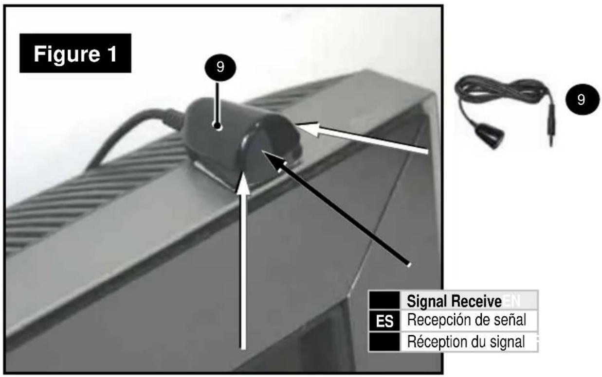
IMPORTANT NOTE: The IR Receiver Must be placed with the Top of the Head facing forward (see Figure 1)
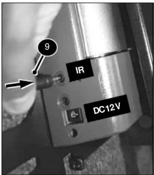
Plug the IR Male End into the Mount
natural_image
Illustration of a blank tablet device with a small circular icon labeled '9' on top (no text or symbols on the device itself)The recommended mounting position is on top of TV.
POWER CORD
WARNING!!
DO NOT PLUG IN DC12V (POWER CORD) UNTIL ALL COMMUNICATION CABLES (IR RECIEVER, RS 232 [Not Included]) ARE PLUGGED IN.
natural_image
Black-and-white photo of a charging plug with coiled cable and a numbered circle (7) in the corner, no visible text or symbols on the device itself.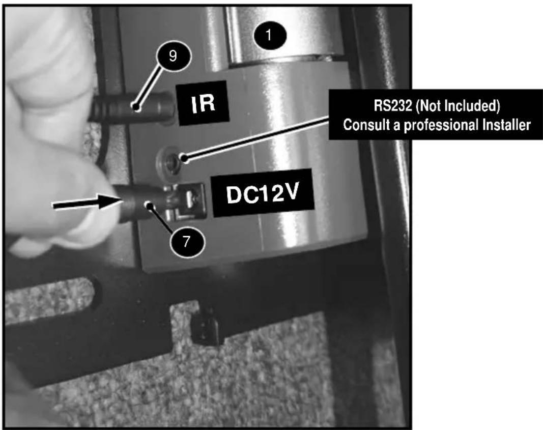

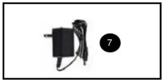
Plug / Attach all communication Cables. Plug the DC12V (Power) into Mount.
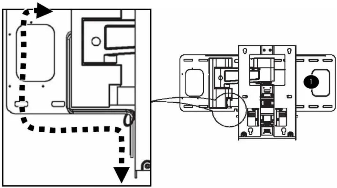
CABLE MANAGEMENT
| Route CablesEN | |
| ES | Tienda los cables |
| FR | Installez les câbles |
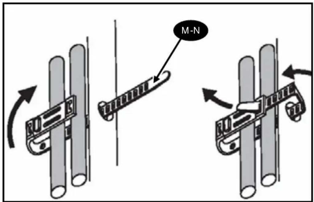
Secure Loose Cables with Zip Ties (M-N)
| Tighten | |
| ES | Ajustar |
| FR | Serrer |
REMOTE CONTROL PROGRAMMING
(English)
ATTENTION!
Must set WALL DETECT RIGHT first. Failure to do this may result in poor performance of Wall
Mount. If set LEFT WALL DETECT, please use the SETUP / RESET to clear memory
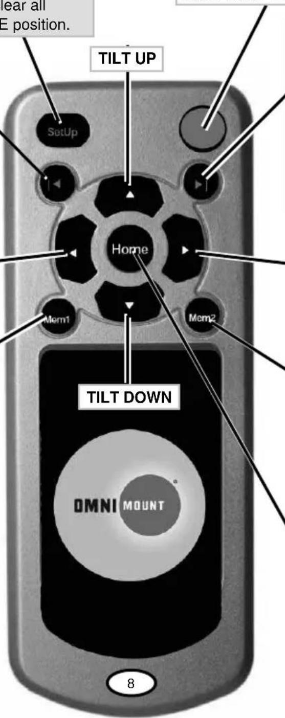
SETUP:
Push / Collapse the Wall Mount Flat against the Wall, Press and Hold for 5 seconds to set the home position (note: this also clears all memorized commands)
RESET: Hold for 5 seconds to clear all commands and memorize HOME position.
STEP 2
WALL DETECT LEFT
Swivel to the closest to the Wall without the TV touching the Wall, leave about 1" (25mm) of space recommended, Hold down Wall Detect for 5 seconds till LED LIGHT color turns solid
LEFT SWIVEL
MEMORY 1:
Hold for 5 Seconds until LED LIGHT color turns sold, memory is set Move to another desired location and repeat above step to memorize again.
LED LIGHT
Flashing LED: Transmitting Signal Solid Color LED: Memory Set or Cancelled
STEP 1
WALL DETECT RIGHT
Swivel to the closest to the Wall without the TV touching the Wall, leave about 1" (25mm) of space recommended, Hold down Wall Detect for 5 seconds till LED LIGHT color turns solid
RIGHT SWIVEL
MEMORY 2:
Hold for 5 Seconds until LED LIGHT color turns sold, memory is set Move to another desired location and repeat above step to memorize again.
HOME
This will bring the wall mount back to the wall of HOME position that user setup, if user needs to set a different Home position, please refer to SETUP button above for details.

ATTENTION!
Power Loss or interruption DOES NOT delete or clear the memory. User must use the SETUP / RESET button to clear memory.
If Swivel too far RIGHT or LEFT and hits / makes contact with the wall, the unit will Stop after 2 seconds.
ATENCION!
INCLINAR HACIA ARRIBA
natural_image
Cross-sectional view of a mechanical component or housing (no visible text or symbols)
natural_image
Cross-sectional view of a mechanical component or housing (no visible text or symbols)Good No Good
- Trouble Shooting
- Unit Must be Level. If not level, TV will lean on one side and Operation Speed will be irregular. Longevity of mount use will be greatly reduced from not properly leveling the wall plate.
• Wall Screws and Mounting Location
- Wood Stud: Wall Mount Must have at least 4 Wall Point Location Mounted. Any Wood Stud Installation Greater than 16" Wide Must use a Dry Wall Anchor (Not Included) in the (B-Left) mounting Section - Refer to the Wall Template for additional Information.
- Spring Tension
- If the Tilt function is non-operational on your mount, check the depth of your TV. If the depth is less then 6 cm it is considered a Slim TV, and the Spring Tension screws must be removed (See page 15).
- Communication / IR / Power Cord
- The Power Cord must be installed last after you have already installed the Communication IR cable or RS 232 (Not Included). Installation order should be: IR Receiver or RS232 (Not Included) then Power Cord.
- Initial Setup
- User must set up the Right and Left Swivels Limits. User must setup the Right side FIRST before setting up the Left Side.
OMNIMOUNT PRODUCT WARRANTY
ENGLISH
This warranty applies to US Residents who purchase from an authorized OmniMount Dealer. OmniMount products are covered against defects in materials and workmanship for 1 years. OmniMount will repair or replace the defective component or product, at its sole discretion.
- To obtain warranty service, contact OmniMount customer service at 800.MOUNT.IT (800.668.6848) or info@omnimount.com. You must supply a copy of your original receipt. If your product must be shipped to OmniMount for inspection, you will be responsible for the shipping charges. Replacement product shipped to you will be returned freight pre-paid.
- OmniMount disclaims any liability for modifications, improper installations, or installations over the specified weight range. To the maximum extent permitted by law, OmniMount disclaims any other warranties, expressed or implied, including warranties of fitness for a particular purpose and warranties of merchantability. OmniMount will not be liable for any damages arising out of the use of, or inability to use, OmniMount products. OmniMount bears no responsibility for incidental or consequential damages. This includes, but is not limited to, any labor charges for the repair of OmniMount products performed by anyone other than OmniMount.
- This warranty gives you specific legal rights, and you may also have other rights which vary from state to state.
■ Specifications are subject to change without prior notice.
ESPAÑOL
THANK YOU FOR PURCHASING AN OMNIMOUNT PRODUCT
GRACIAS POR ADQUIRIR UN PRODUCTO DE OMNIMOUNT
MERCI D'AVOIR ACHETÉ UN PRODUIT OMNIMOUNT

OmniMount Systems, Inc.
8201 South 48th Street
Phoenix, AZ 85044-5355
1-800-MOUNT-IT (1-800-668-6848)
www.omnimount.com

- Instruction Manual EN
- WOOD STUD INSTALLATION
- Wood Pilot
- Masonry Pilot
- HAND TIGHTEN ONLY!
- READ!!! SLIM TV (6 cm thickness or less only)
- VESA
- VESA MONITOR INSTALLATION
- Do Not Tighten
- NON-VESA / LARGER MONITOR INSTALLATION
- IR RECEIVER
- POWER CORD
- CABLE MANAGEMENT
- REMOTE CONTROL PROGRAMMING
- (English)
- ATTENTION!
- SETUP:
- STEP 2
- WALL DETECT LEFT
- LEFT SWIVEL
- MEMORY 1:
- LED LIGHT
- STEP 1
- WALL DETECT RIGHT
- RIGHT SWIVEL
- MEMORY 2:
- HOME
- ATENCION!
- INCLINAR HACIA ARRIBA
- - Trouble Shooting
- • Wall Screws and Mounting Location
- - Spring Tension
- - Communication / IR / Power Cord
- - Initial Setup
- OMNIMOUNT PRODUCT WARRANTY
- ENGLISH
- ESPAÑOL
Brand : OmniMount
Model : POWER 55
Category : Motorized wall mount for TV