TURNTEC T2 - Bike lighting Busch + Müller - Free user manual and instructions
Find the device manual for free TURNTEC T2 Busch + Müller in PDF.


User questions about TURNTEC T2 Busch + Müller
0 question about this device. Answer the ones you know or ask your own.
Ask a new question about this device
Download the instructions for your Bike lighting in PDF format for free! Find your manual TURNTEC T2 - Busch + Müller and take your electronic device back in hand. On this page are published all the documents necessary for the use of your device. TURNTEC T2 by Busch + Müller.
USER MANUAL TURNTEC T2 Busch + Müller
text_image
Technical diagram of a mechanical device with numbered components for identification
text_image
Diagram showing three groups of keys with checkmarks and crosses, likely illustrating a logic or selection process.- General information Page 18
- Packaging contents Page 18
- Safety information Page 19
- Legal regulations Page 20
- Technical specification Page 20
- Assembly Page 21
6.1. Positioning Page 21
6.2. Assembly Page 21 - Operation Page 24
7.1. Charging the battery Page 25
7.2. Configuring Page 26 - Further information Page 28
- Liability Page 29
text_image
Technical diagram of a mechanical device with numbered components for identification
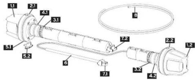
Left Indicator Right indicator Left ring button Right ring button Left knurled nut

Right knurled nut Left rubber pads Pressure rubber, right USB-C socket USB cap
6 Black support tube 7.1 Plug 7.2 Socket 8 Cable feed-through aid
Installation and operating instructions for busch+müller TURNTEC T2 bicycle indicators Not approved for vehicles requiring license plates fast E-Bikes)
1. General information
These instructions are directed at persons with knowledge and experience in the assembly of bicycle components. Specialist tools may be required. Should you not have such experience or the required tools please enlist the service of a cycle specialist to ensure that this assembly is carried out correctly. Improper assembly may result in a fail or crash resulting in serious injury. Please read these instructions thoroughly and retain them for future reference, follow all the steps described and keep it in a safe place.
2. Packaging contents
Left indicator, type 681(L) (long) | Right indicator, 681(R) (short) | Cable feed-through aid | Installation and operating instructions
3. Safety information
These instructions implement signal words to highlight potential dangers or important information. The meaning of the signal words is listed below:
WARNING Describes a hazardous situation which, if not avoided, could result in a fatal accident or serious injury.
NOTICE Indicates information considered important, but not hazard-related (e.g. information related to property damage).
The 1 symbol is used to provide other useful information about your new bicycle component.
WARNING
battery to fire. Improper use such as overcharging or short circuit may result in explosion or fire.

NOTICE Bicycle components from busch+müller are suited to riding conditions on a firm riding terrain. Avoid use under extreme circumstances and never ride down steps or stairs. Do not use B+M components while performing jumps, stunts, tricks, hops or fast descents on uneven terrain.
4. Legal regulations
Before you operate your vehicle in public traffic, you are obliged to ensure that your vehicle complies with national and local laws and regulations, and you, as a traffic participant must abide by the traffic regulations that apply. These can be found in the Highway Code or national equivalent, and depending on the country, also at other sources.
The prescribed mounting height for direction indicators in Germany is between 25 and 120 cm.
! Your bicycle lights should never be covered. Ensure that the lights are properly installed and aligned.
5. Technical specification
Dimensions of indicator: Width: 42 mm | Height: 41 mm | Depth: 39 mm | Weight: 165 g Battery capacity: 700 mAh
6. Assembly
6.1. Positioning
The busch+müller TURNTEC T2 bicycle indicator is designed for mounting on handlebars with a maximum angle of 0-20° and inner handlebar diameters of 17.5 mm to 19.5 mm.
The longer indicator unit is intended for the left-hand side of the handlebars when riding. 1.1 The short indicator unit is intended for the right-hand side in the direction of travel 1.2 The indicators 1.1 & 1.2 must be mounted so that the arrows on the top are centred. The left/right and top/bottom alignment is essential to ensure maximum visibility of the indicators.
6.2. Assembly
- Insert the cable insertion aid 8 into the open end of the black support tube 6 from the right-hand side of the indicator and push the plug 7.1 together with the black support tube 6 into the handlebar from the right until the plug 7.1 and the black support tube 6 protrude from the left-hand side of the handlebar.
-
Hold the black support tube 6 and the plug 7.1 in place and carefully pull the cable insertion aid 8 back out of the handlebar so that the cable remains threaded through the handlebar.
-
Turn the knurled nut 3.2 of the right indicator unit 1.2 clockwise until the two rubber pressure pads 4.2 are spread far enough to just fit into the handlebar end.
- Insert the right indicator unit 1.2 completely into the handlebar so that there is no gap between the end of the handlebar and the indicator unit 1.2. Then turn the right indicator unit 1.2 clockwise until it is tight enough that the indicator 1.2 will not move when operated later. If the resistance does not increase and the indicator unit 1.2 cannot be tightened further, the pressure rubbers 4.2 are not yet spread far enough and the knurled nut 3.2 must be lightened again.
Make sure that the indicator arrow shown is visible at the top of the indicator 1.2 - Insert the plug 7.1 of the cable end into the socket 7.2 of the left indicator 1.1 and, again using the knurled nut 3.1 spread the pressure rubbers 4.1 far enough so that they just fit into the handle bar end.
- Insert the left indicator unit 1.1 completely into the handlebar so that there is no gap between the handlebar end and the indicator unit 1.1. Then turn the left indicator unit 1.1 clockwise until it is tight enough that the indicator 1.1 will not move when operated later. If the resistance does not increase and the indicator unit 1.1 cannot be tightened further, the pressure rubbers 4.1 are not yet spread far enough and the knurled nut 3.1 must be tightened again. Ensure that the indicator arrow shown is visible at the top of the indicator 1.1
text_image
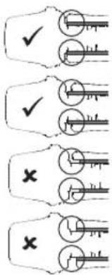
Diagram showing three groups of keys with checkmarks and crosses, likely illustrating a logic or selection process.Handlebars and grips flush. Indicators flush with handlebars. Indicators fit the handlebars as desired.
Handlebars and grips not flush. Indicators flush with handlebars. Indicators fit the handlebars as desired.
Handlebars and grips not flush. Indicator not flush with handlebars because handle protrudes. Attention! Indicator does not sit flush with handlebars! Please change!
Handlebars and handle flush. Indicator not flush with handlebars. Attention! Indicator does not sit flush with handlebars! Please change!
7. Operation
The indicator 1.1 & 1.2 is switched on by pressing the ring button 2.1 & 2.2, which is marked with an arrow pointing towards the indicator end.
The indicator is preconfigured to flash 15 times after a short press of the ring button. (Tapping flash)
For longer flashing, the ring button must be held down for at least 1.5 seconds. The flashing cycle can be ended by pressing the button again or it switches off automatically after 4 minutes.
Hazard warning lights: To switch on, press and hold both buttons (left and right) for 3 seconds. Switch off by pressing the button again.
7.1. Charging the battery:
The TURNTEC T2 indicator has a replaceable lithium-ion battery with 700 mAh.
The battery must be charged before first use. To charge, pull the USB cap5.2 out of the
USB socket 5.1 on the left indicator 1.1 and connect a USB-C cable to the USB-C socket
5.1 Connect the USB-C cable to a power supply, a computer or a busch+müller headlight with activated power bank function. During charging, the left indicator 1.1 shows that charging is in progress by means of a red LED.
Once the battery is full, charging stops and the red LED goes out.
If the battery capacity falls below 10%, the flashing frequency of all indicators will increase significantly.
To protect against moisture or dirt, always keep the USB socket 5.1 closed with the supplied USB cap 5.2 and plug it back into the USB socket 5.1 after charging is complete.
7.2. Configuring:
The number of flashes after activating the direction indicator can be individually configured between 5 and 30.
Preparation for TURNTEC configuration:
The TURNTEC T2 bicycle indicator does not flash and is not charging.
Press and hold the ring button 2.1 on the left indicator unit 1.1
Connect the charging plug with the charger (mobile phone, power bank, etc.) connected.
Hold the ring button 2.1 and wait ...
Start of configuration:...
wait until the front-facing flashing LED lights up continuously.
Release the ring button 2.1 on the left indicator.
The Indicator goes out.
Set the duration of the flashing cycle:
The front-facing flashing LED on the left indicator 11 starts flashing.
Once the desired number of flashes has been reached, press the ring button 2.2 on the right indicator
unit 1.2
26 27
TURNTEC T2 confirms the configuration with alternating front/rear flashing of the left indicator and is then ready for use again.
If the button ring 2.2 of the right-hand control unit 1.2 is pressed before the minimum length (5 flashes) is reached, this is ignored.
If the ring button 2.2 on the right-hand control unit 1.2 is not pressed before the maximum length (30 flashes) is reached, this will be ignored.
Resetting to factory settings:
If the button ring 2.1 on the left indicator 1.1 is pressed during the 'Set duration of flashing cycle' step, the TURNTEC T2 will be reset to factory settings.
The TURNTEC T2 will confirm the reset to factory settings by the left indicator unit 1.1 lighting up for a longer period of time and will then be ready for use again.
8. Further information
Cleaning: Protect your busch+müller product from high-pressure water jets.
Never point a water hose or high-pressure cleaner directly at the product.
Transport: If you are transporting your bicycle by car in the rain, cover the indicators with a plastic bag, for example, to protect them from moisture.
Disposal: Electronic components do not belong in household waste, but must be disposed of as hazardous waste.
Repairs: In the event of defects, please contact your bicycle dealer or our service department at service@bumm.de or +49 2354 915-7111.
9. Liability
Damage caused by improper handling (e.g. dropping the busch+müller product, insufficiently secure mounting and its consequences, immersion in water or other liquids, etc.) is excluded from the warranty. The warranty also expires if the indicators are opened.
We hope you enjoy your new product from busch+müller and wish you safe travels at all times!
Spare parts can be found in our spare parts shop at www.bumm-shop.de
Subject to technical changes.
Busch & Müller KG • 58540 Meinerzhagen, Germany • Tel. +49 2354 915-7111 • service@bumm.de • www.bumm.de
Table des matières
text_image
Technical diagram of a mechanical device with numbered components for identificationtext_image
Diagram showing three identical hand-drawn keys with checkmarks and X marks, likely illustrating a correct or incorrect matching rule.text_image
Technical diagram of a mechanical device with numbered components for identification