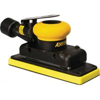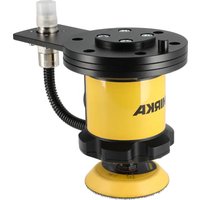
AIROS 300P - Sander Mirka - Free user manual and instructions
Find the device manual for free AIROS 300P Mirka in PDF.


User questions about AIROS 300P Mirka
0 question about this device. Answer the ones you know or ask your own.
Ask a new question about this device
Download the instructions for your Sander in PDF format for free! Find your manual AIROS 300P - Mirka and take your electronic device back in hand. On this page are published all the documents necessary for the use of your device. AIROS 300P by Mirka.
USER MANUAL AIROS 300P Mirka
natural_image
Yellow MIRKA industrial machine with black housing and attached pipe (no visible text or symbols)
natural_image
Stylized illustration of a bulldog in aggressive posture (no text or symbols)Mirka ^® AIRP
300
Operating instructions (original)......12en
NOTE! Repairs done by non-authorized repairer will breach the Mirka warranty.
Electrical tools must be serviced by a qualified repair person and in accordance with national requirements.
Parts list – AIRP 300 spareparts & accessories
| Quantity Kit Defining Item torque | |||||
| 1 | Screw M6x10 DIN 912 8.8 ZN | A | 4 | 10 Nm/7,4 ft-lb | |
| 1Flange ISO | 9409-1-80-6-M82MIA651011* | ||||
| 3 | Screw M6x10 DIN 7991 10.9 | A | 2 | 8 Nm/5,9 ft-lb | |
| 1Connector | Plate4MIA3010411 | ||||
| 1Housing* | 5MIA3010611 | ||||
| 6 | Screw M4x10 TX ISO 7380 | A | 6 | ||
| 7MIA3010Tag Holde | 0,8 Nm/0,6 ft-lb | ||||
| 8MIA3010Holde | 2,4 Nm/1,8 ft-lb | ||||
| 9 | Screw M3x10 TX ISO 14579 8.8 ZN | A | 4 | 1,8 Nm/1,3 ft-lb | |
| 8993008013 | 10 | 1Pad Wrench | 17mm | ||
| 8294791311 | 11 | 1Backing Pad | 77mm | ||
| MIA3011211 | 12 | 1O-Ring | 55x2.0 mm | ||
* Spare parts only available to authorized repairers.
Gewährleistung
| ISO 9409-1-80-6-M8FLANSCHPhoenix Contact ST-8EP1N8ACK04SNET | 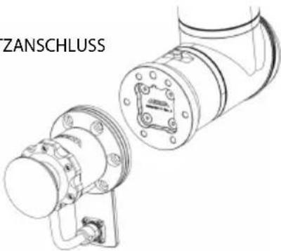 |
natural_image
Mechanical assembly diagram showing a cylindrical component inserted into a base plate with directional arrows indicating motion (no text or symbols)Wartung

natural_image
Technical line drawing of a MIRKA industrial machine component (no text or symbols on the diagram itself)Fehlerbehebung
Mirka warrants that your components are free from manufacturing and material defects.
Mirka components have a 1-year warranty starting from the date of purchase. Only manufacturing and material defects are covered by the warranty.
If a problem occurs caused by a manufacturing defect material or by workmanship, Mirka will repair your component free of charge in accordance with the warranty terms and conditions stated herein. To keep your component warranty valid the component must be used, maintained and operated in compliance with the operating instructions.
Terms and conditions
Mirka's component warranty covers defects in material and workmanship.
Components covered by the warranty:
•motor drive
•polishing unit
•power supply
- communication gateway
Warranty does not cover:
- any damage caused or resulting from transport, receipt of delivery, installation, commissioning, misuse, neglect in usage or maintenance, accidents, exposure to extreme unacceptable ambient temperature, acids, water, unsuitable storage, excessive impact, or operation outside the rated specifications.
• defects caused by spare parts, accessories or components other than Mirka original spare parts or accessories. - normal wear and tear items such as: backing pad, break seal, exhaust fitting, bearings, rubber mount, signal cable or power cable.
- components that have been: modified, repaired or repair attempts (by other than Mirka authorized service), partly or completely disassembled components.
No other than Mirka have the authority to change, extend or add to given warranty terms and conditions.
The manufacturer cannot be hold responsible for consequential damages compensations for downtime, production loss, injuries or property damages.
A warranty claim must be submitted with as short delay as possible. A warranty claim must be submitted within the warranty period.
Important
Read these safety and operating instructions carefully before installing, operating or maintaining this tool. Keep these instructions in a safe and accessible place. Read and comply with state and local regulations.
Required personal safety equipment

Read
operator's manual

Wear safety glasses

Wear
ear protection

Wear safety gloves

Wear
face mask
Symbols
AIRP
Automated Industrial Rotating Polisher

Warning: Potential hazardous situation that may result in death or serious injury and/or property damage. Caution: Potential hazardous situation that may result in minor or moderate injury and/or property damage.

General Power Tool Safety Warnings

WARNING Read all safety warnings and all instructions. Failure to follow the warnings and instructions may result in electric shock, fire and/or serious injury. Save all warnings and instructions for future reference. The term “power tool” in the warnings refers to your mains-operated (corded) power tool or battery-operated (cordless) power tool.
Work area safety1.
a. Keep work area clean and well lit. Cluttered or dark areas invite accidents.
b. Do not operate power tools in explosive atmospheres, such as in the presence of flammable liquids, gases or dust. Power tools create sparks which may ignite the dust or fumes.
c. Keep children and bystanders away while operating a power tool. Distractions can cause you to lose control.
Electrical safety2.
a. Power tool plugs must match the outlet. Never modify the plug in any way. Do not use any adapter plugs with earthed (grounded) power tools. Unmodified plugs and matching outlets will reduce risk of electric shock.
b. Avoid body contact with earthed or grounded surfaces, such as pipes, radiators, ranges and refrigerators. There is an increased risk of electric shock if your body is earthed or grounded.
c. Do not expose power tools to rain or wet conditions. Water entering a power tool will increase the risk of electric shock.
d. Do not abuse the cord. Never use the cord for carrying, pulling or unplugging the power tool. Keep cord away from heat, oil, sharp edges and moving parts. Damaged or entangled cords increase the risk of electric shock.
f. If operating a power tool in a damp location is unavoidable, use a residual current device (RCD) protected supply. Use of an RCD reduces the risk of electric shock.
Personal safety3.
a. Stay alert, watch what you are doing and use common sense when operating a power tool. Do not use apowertool while you are retired under the influence of drugs, alcohol or medication. A moment of inattention while operating power tools may result in serious personal injury.
b. Use personal protective equipment. Always wear eye protection. Protective equipment such as a dust mask, non-skid safety shoes, hard hat, or hearing protection used for appropriate conditions will reduce personal injuries.
d. Remove any adjusting key or wrench before turning the power tool on. A wrench or a key left attached to a rotating part of the power tool may result in personal injury.
f. Dress properly. Do not wear loose clothing or jewellery. Keep your hair, clothing and gloves away from moving parts. Loose clothes, jewellery or long hair can be caught in moving parts.
g. If devices are provided for the connection of dust extraction and collection facilities, ensure these are connected and properly used. Use of dust collection can reduce dust-related hazards.
h. Do not let familiarity gained from frequent use of tools allow you to become complacent and ignore tool safety principles. A careless action can cause severe injury within a fraction of a second.
4. Power tool use and care
a. Do not overload the power tool. Use the correct power tool for your application. The correct power tool will do the job better and safer at the rate for which it was designed.
c. Disconnect the plug from the power source and/or the battery pack from the power tool before making any adjustments, changing accessories, or storing power tools. Such preventive safety measures reduce the risk of starting the power tool accidentally.
d. Store idle power tools out of the reach of children and do not allow persons unfamiliar with the power tool or these instructions to operate the power tool. Power tools are dangerous in the hands of untrained users.
e. Maintain power tools and accessories. Check formalignmentorbindingofmoving parts, breakage of parts and any other condition that may affect the power tool's operation. If damaged, have the power tool repaired before use. Many accidents are caused by poorly maintained power tools.
g. Use the power tool, accessories and tool bits etc. in accordance with these instructions, taking into account the working conditions and the work to be performed. Use of the power tool for operations different from those intended could result in a hazardous situation.
Service5.
a. Have your power tool serviced by a qualified repair person using only identical replacement parts. This will ensure that the safety of the power tool is maintained.

Safety warnings common for polishing
a. This power tool is intended to function as a polisher. Read all safety warnings, instructions, illustrations and specifications provided with this power tool. Failure to follow all instructions listed below may result in electric shock, fire and/or serious injury.
b. Operations such as grinding, sanding, wire brushing or cutting-off are not recommended to be performed with this power tool. Operations for which the power tool was not designed may create a hazard and cause personal injury.
c. Do not convert this power tool to operate in a way which is not specifically designed and specified by the tool manufacturer. Such a conversion may result in loss of control and cause serious personal injury.
d. Do not use accessories which are not specifically designed and recommended by the tool manufacturer. Just because the accessory can be attached to your power tool, it does not assure safe operation.
e. The rated speed of the accessory must be at least equal to the maximum speed marked on the power tool. Accessories running faster than their rated speed can break and fly apart.
f. The outsidediameter and the thickness of your accessory must be within the capacity rating of your power tool. Incorrectly sized accessories cannot be adequately guarded or controlled.
g. The dimensions of the accessory mounting must fit the dimension of the mounting hardware of the power tool. Accessories that do not match the mounting hardware of the power tool will run out of balance, vibrate excessively and may cause loss of control.
h. Do not use a damaged accessory. Before each use inspect the accessory such as abrasive wheels for chips and cracks, backing pad for cracks, tear or excess wear, wire brush for loose or cracked wires. If power tool or accessory is dropped, inspect for damage or install an undamaged accessory. After inspecting and installing an accessory, position yourself and bystanders away from the plane of the rotating accessory and run the power tool at maximum no-load speed for one minute. Damaged accessories will normally break apart during this test time.
i. Wear personal protective equipment. Depending on application, use face shield, safety goggles or safety glasses. As appropriate, wear dust mask, hearing protectors, gloves and workshop apron capable of stopping small abrasive or workpiece fragments. The eye protection must be capable of stopping flying debris generated by various operations. The dust mask or respirator must be capable of filtrating particles generated by your operation. Prolonged exposure to high intensity noise may cause hearing loss.
j. Keep bystanders a safe distance away from work area. Anyone entering the work area must wear personal protective equipment. Fragments of workpiece or of a broken accessory may fly away and cause injury beyond immediate area of operation.
o. Do not operate the power tool near flammable materials. Sparks could ignite these materials.
p. Do not use accessories that require liquid coolants. Using water or other liquid coolants may result in electrocution or shock.
NOTE! The above warning does not apply for power tools specifically designed for use with a liquid system.

Additional safety instructions for polishing operations
Safety warnings specific for polishing operations
a. Do not allow any loose portion of the polishing bonnet or its attachment strings to spin freely. Tuck away or trim any loose attachment strings. Loose and spinning attachment strings can entangle your fingers or snag on the workpiece.
Technical data
| ° | AIRP 300Mirka |
| 48VDCRated voltage | |
| 350WRated power | |
| 1,000–3,000rpmSpeed | |
| 0mm(0")Orbit | |
| 43mmCenter of Gravity | |
| Size of backing pad | ∅ 77 mm (3") |
| Tool offset (with the included pad) | 122 ± 1 |
| 1.4kg(3.1lbs)Weight | |
| IIIDegree of protection | |
| IP66IP Classification |
Installation overview
Interfaces
ISO 9409-1-80-6-M8FLANGE
Phoenix Contact ST-8EP1N8ACK04SPOWER CONNECTION
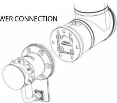
text_image
WER CONNECTIONInstallation steps
- Remove dust protector cap from the connector.
- Mount the tool on a matching counter-flange. If the force sensor or the robot used has a flange of a different size an adapter may be required. If the counter-flange is larger by a significant amount there may be a need for an increaseintool offset on the adapter to prevent unnecessary wear, or obstruction of the hose and cable.
- All six (6) M8 screw holes should be used to ensure a robust connection. Note that the pivot pin location is at the front of the tool.
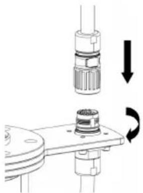
- Connect the power cable to the tool by inserting and twisting the connector counter-clockwise to the "lock" position.
natural_image
Mechanical assembly diagram showing a connector with a rotating shaft and a base, no text or symbols present.Maintenance

Always disconnect the power before maintenance! Only use original Mirka spare parts!
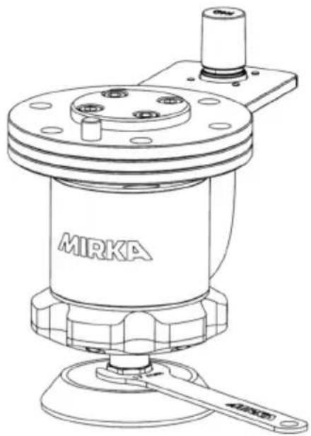
Replacing the backing pad
AIRP 300
- Hold the spindle nut with the pad wrench
- Turn the backing pad counterclockwise to remove it.
- Fit and tighten the new backing pad with washers.
- Remove the pad wrench.
natural_image
Technical line drawing of a MIRKA industrial pump or motor assembly (no text or symbols on the diagram itself)Troubleshooting guide
| Recommended proceduresSymptom | |
| The tool slows down in use. | Check the temperatures of the tool and the motor drive.Reduce the load on the tool. |
Garantía
natural_image
Technical line drawing of a mechanical assembly with flanged components and mounting bracket (no text or symbols)natural_image
Mechanical component diagram showing a rotating knob and base plate (no text or symbols)Mantenimiento

natural_image
Technical line drawing of a MIRKA industrial machine component (no text or symbols on the diagram itself)natural_image
Technical line drawing of a mechanical assembly with flanged components and a separate housing (no text or symbols)Étapes de montage
natural_image
Mechanical assembly diagram showing a cylindrical component being inserted into a base plate with directional arrows indicating motion (no text or symbols)Maintenance

natural_image
Technical line drawing of a MIRKA industrial machine component (no text or symbols on the device itself)Guide de dépannage
natural_image
Technical line drawing of a mechanical assembly with flanged components and mounting brackets (no text or symbols)Kroki instalacji
natural_image
Mechanical assembly diagram showing a cylindrical component being inserted into a base plate with directional arrows indicating motion (no text or symbols)Konserwacja

natural_image
Technical line drawing of a MIRKA industrial machine component (no text or symbols on the device itself)Instrukcja naprawy
natural_image
Mechanical assembly diagram showing a connector with a rotating shaft and a base, no text or symbols present.natural_image
Technical line drawing of a MIRKA industrial pump or motor assembly (no text or symbols on the diagram itself)EC-Declaration of Incorporation.
We declare under our sole responsibility that this partly completed machinery is in conformity with all relevant provisions of the following directives including their amendments and complies with the standards and essential health and safety requirements stated.
The partly completed machinery must not be put into service until the final machinery into which it is to be incorporated has been declared in conformity with the provisions of 2006/42/EC, where appropriate.
es
Place and date of issue
Manufacturer / Supplier
Mirka Ltd
66850 Jeppo, Finland
Tel. +358 20 760 2111
Fax +358 20 760 2290
www.mirka.com
geo
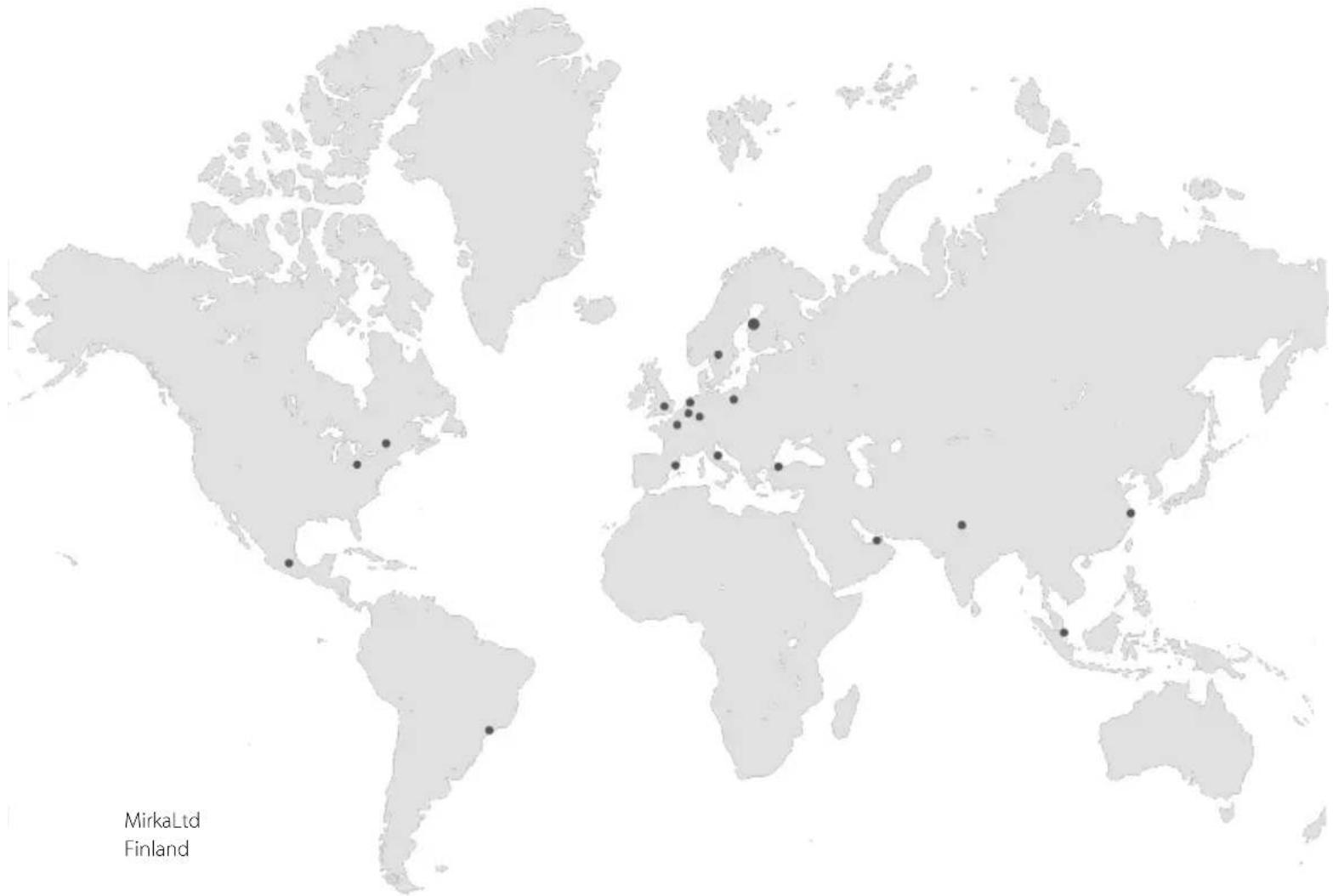
| Location | Marker | | -------- | ------ | | Mirka Ltd | 1 | | Finland | 2 |MirkaLtd
Finland
BrazilMirkaBrasilLtda.
BelgiumMirkaBelgiumLogisticsNV
CanadaMirkaCanadalnc.
ChinaMirkaTradingShanghaiCo.,Ltd
Finland&BalticsMirkaLtd
FranceMirkaFranceSarl
GermanyMirkaGmbH
IndiaMirkalndiaPvtLtd
ItalyMirkaltalias.r.l.,CafroS.p.A.
MexicoMirkaMexicanaS.A.deC.V.
NetherlandsMirkaBeneluxB.V
PolandMirkaPolandSp.zo.o
SingaporeMirkaAsiaPacificPteLtd
SpainKWHMirkalbéricaS.A.U.
SwedenMirkaScandinaviaAB
TurkeyMirkaTurkeyZimparaLtdŞirketi
UnitedKingdomMirka(UK)Ltd
UnitedArabEmiratesMirkaMiddleEastFZCO
USAMirkaUSAInc.
Forcontactinformation,
pleasevisitwww.mirka.com