H-10066 - Stapler Uline - Free user manual and instructions
Find the device manual for free H-10066 Uline in PDF.

User questions about H-10066 Uline
0 question about this device. Answer the ones you know or ask your own.
Ask a new question about this device
Download the instructions for your Stapler in PDF format for free! Find your manual H-10066 - Uline and take your electronic device back in hand. On this page are published all the documents necessary for the use of your device. H-10066 by Uline.
USER MANUAL H-10066 Uline
OVERVIEW OF CONTROLS
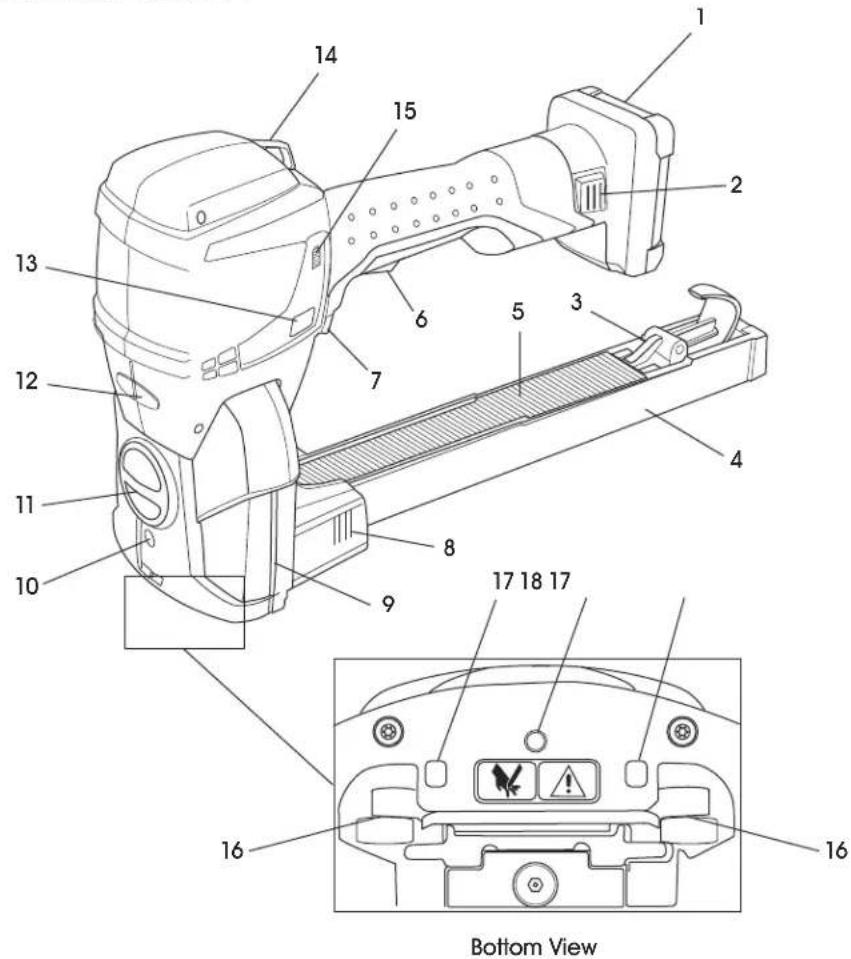
CONTROL PANEL
| # DESCRIPTION |
| 1 Battery |
| 2 Battery Release |
| 3 Magazine Pusher |
| 4 Magazine with Staple Type Indicator |
| 5 Staples |
| 6 Safety Latch |
| 7 Trigger |
| 8 Magazine Quick Snap System |
| 9 Tool Status Indicator |
| 10 Screw for Staple Length Adjustment |
| 11 Penetration Depth Setting Knob |
| 12 Staple Clinch Adjusting Nut |
| 13 Mode Button |
| 14 Suspension Hanging Port |
| 15 Battery Charge Status Indicator |
| 16 Clinchers |
| 17 Box Detection Indicator |
| 18 Locking Screw for Staple Length Adjustment |
SAFETY

NOTE: These tools are manufactured without any chemical substances that could be dangerous to health. Potential health damage may occur from battery liquid if batteries are treated or disposed of improperly. Chargers and batteries should be sorted for environmentally friendly recycling and disposed of separately.

NOTE: Laws regarding the disposal of all parts must be observed.
- Chargers and batteries should be sorted for environmentally friendly recycling.
- Observe warnings and instructions of the battery manufacturer stated in the operating instructions of the battery.
STOP
WARNING! Read all safety warnings and instructions. Failure to follow the warnings and instructions may result in electric shock, fire and/or serious injury. Save all warnings and instructions for future reference.
- Always assume the stapler contains staples.
- Do not point the stapler toward user or others. Unexpected triggering will discharge the staple, causing an injury.
- Do not actuate stapler unless it is placed firmly against the work piece. If tool is not in contact with the work piece, the staple may be deflected away from target.
- Use caution while removing a jammed staple. The mechanism may be under compression and the staple may be forcefully discharged while attempting to free a jammed staple.
- Stapler is intended for closing boxes made from corrugate. It is intended for stapling with staples as specified on page 5. Only use stapler as described in these instructions.
- Do not use staples that are not listed on page 5.
- Do not place any staples into unsuitable material.
- Never use stapler to attach electrical cables.
- Do not modify stapler without prior authorization
- Never direct position guidance laser at other people.
These instructions must always be available at the place of operation of the stapler. They must be read and observed by all persons working with, or in the vicinity of, the stapler.
- Preventive and corrective maintenance on the tool may only be carried out by trained personnel. In addition to these instructions, the applicable local rules for accident prevention and safe and professional operation must be observed.
- The operator or their supervisor is responsible for safe stapling and the selection of the correct staples (as specified on page 5) for the package, depending on its dimensions, weight, stability and the way it will be transported and stored.
- Only staples specified for the stapler type may be used (see page 5). The stapler should be adjusted appropriately for the staples and the package used. The operator is responsible for the correct tool settings and adjustments.
- When operating the tool, wear hand protection (cut resistant gloves) and safety shoes.
- Safety goggles should always be worn by the operator and others in the work area when loading, operating or servicing stapler.
- Keep the work area clean and well-lit. Cluttered or dark areas invite accidents.
- Do not operate power tools in explosive atmospheres, such as in the presence of flammable liquids, gases or dust. Power tools create sparks that may ignite the dust or fumes.
- Keep children and bystanders away while operating unit. Distractions can cause user to lose control.
- Power tool plugs must match the outlet. Never modify the plug in any way. Do not use any adapter plugs with earthed (grounded) power tools. Unmodified plugs and matching outlets will reduce the risk of electric shock.
- Avoid body contact with earthed or grounded surfaces such as pipes, radiators, ranges and refrigerators. An increased risk of electric shock can occur if body is earthed or grounded.
- Do not expose stapler to rain or wet conditions. Water entering stapler will increase risk of electric shock.
SAFETY CONTINUED
- Do not abuse the cord. Never use the cord for carrying, pulling or unplugging the stapler. Keep the cord away from heat, oil, sharp edges or moving parts. Damaged or entangled cords increase the risk of electric shock.
- Using an extension cord suitable for outdoor operation reduces the risk of electric shock.
- If operating in a damp location is unavoidable, use a residual current device (RCD). Use of an RCD reduces the risk of electric shock.
- Stay alert and use common sense when operating a power tool. Do not use a power tool while tired or under the influence of drugs, alcohol or medication. A moment of inattention while operating stapler may result in serious personal injury.
- Use personal protective equipment. Always wear eye protection. Protective equipment such as dust masks, non-skid safety shoes, hard hat or hearing protection used for appropriate conditions will reduce personal injuries.
- Prevent unintentional starting. Ensure the switch is in the off position before connecting to the battery pack, picking up or carrying the tool. Carrying power tools with a finger on the switch or energizing power tools that have the switch on invites accidents.
- Remove any adjusting key or wrench before turning on the power tool. A wrench or key left attached to a rotating part of the unit may result in personal injury.
- Do not overreach. Keep proper footing and balance at all times. This enables better control of the power tool in unexpected situations.
- Do not wear loose clothing or jewelry. Keep hair, clothing and gloves away from moving parts. Loose clothes, jewelry or long hair can be caught in moving parts.
If devices are provided for the connection of dust extraction and collection facilities, ensure these are connected and properly used. Use of dust collection can reduce dust-related hazards. - Do not force the stapler. Use only on corrugate.
-
Do not use the stapler if the switch does not turn it on and off. If stapler cannot be controlled with the switch, it is dangerous and must be repaired.
-
Disconnect battery pack from the stapler before making any adjustments, changing accessories or storing. Such preventive safety measures reduce the risk of starting the stapler accidentally.
- Store idle stapler out of reach of children. Do not allow persons unfamiliar with the stapler or these instructions to operate. Stapler is dangerous in the hands of untrained users.
- Maintain stapler. Check for misalignment or binding of moving parts, breakage of parts and any other condition that may affect operation of the stapler. If damaged, have the stapler repaired before use. Many accidents are caused by poorly maintained power tools.
- Keep cutting tools sharp and clean. Properly maintained cutting tools with sharp cutting edges are less likely to bind and are easier to control.
- Use the stapler and accessories in accordance with these instructions, taking into account the working conditions and the work to be performed. Use of the stapler for operations different from those intended could result in a hazardous situation.
- Recharge only with the charger specified by the manufacturer. A charger that is suitable for one type of battery pack may create a risk of fire when used with another battery pack.
- Use stapler only with specifically designated battery packs. Use of any other battery packs may create a risk of injury and/or fire.
- When the battery pack is not in use, keep it away from other metal objects like paper clips, coins, keys, nails, screws or other small metal objects that can make a connection from one terminal to another. Shorting the battery terminals together may cause burns or a fire.
- Under abusive conditions, liquid may be ejected from the battery; avoid contact. If contact accidentally occurs, flush with water. If liquid contacts eyes, seek medical help. Liquid ejected from the battery may cause irritation or burns.
SAFETY CONTINUED
- Have power tool serviced by a qualified repair person using only identical replacement parts. This will ensure that the safety of the power tool is maintained.
- Do not use this tool for fastening electrical cables. It is not designed for electric cable installation and may damage the insulation of electric cables, thereby causing electric shock or fire hazard.
- Danger of jamming and crushing. Do not place hands or other body parts between or under the tool and the carton during the stapling process.
- Improper stapling can cause loose and falling cartons. Check the staple seal. Never transport packaged goods if loads look unbalanced or incorrect.
- Risk of explosion in EX (explosive) zones. The tool must not be used in areas where explosions can occur as a result of the environment or products being used.
- Damage due to humidity. Do not clean the stapler with water or steam. When using outdoors, protect it from rain. If the stapler or the battery have water damage, it can cause fire or explosion.
- When cleaning with compressed air, no air must penetrate the body via skin lesions. Use only clean and dry compressed air. Use a blow gun with a multi-hole nozzle. Wear eye protection.

CAUTION! The following dangers can result in minor or moderate injury:
NOISE EXPOSURE
Wearing hearing protection is recommended.
VIBRATION EXPOSURE
- The vibration level of stapler is lower than the permissible exposure limit.
-
The vibration level specified in these instructions has been measured according to a measurement method standardized in EN 60745 and can be used for the comparison of power tools with each other. It is also suitable for a preliminary estimation of the vibration load.
-
The vibration emission value measured may, however, deviate from the specified value depending on the actual application and the manner of operation. Under certain circumstances, the vibration load may be increased temporarily or may be significantly smaller over the entire work period. For a more accurate assessment of the actual vibration load, the times should also be considered when the device is switched off or is running but not actually being used. This could reduce the vibration load significantly over the entire work period.
- Define additional safety measures against the effect of vibrations for the protection of the operator, such as maintenance of the tool and organization of work processes.
- Below is warning label on protection plate at the bottom of the stapler and on rear housing:

- Since the box detection sensors do not distinguish between corrugate and the fingers of the operator, there is a risk that the operator may be injured when operating the trigger by driving staples (extending driver blade and clinchers).

CAUTION! To prevent damage to the tool:
Use only original Kihlberg stick staples (Uline model # S-10720 or S-10721).
- Using non-original staples may impair operational safety and will void the warranty and any liability.
If unit is in need of repair or replacement parts, contact Uline Customer Service at 1-800-295-5510.
- Using non-original spare parts may impair operational safety and will void the warranty and any liability.
- Use only batteries and chargers provided with stapler. See Battery and Charger.
SETUP
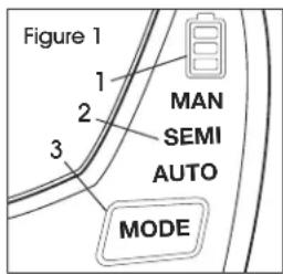
USER INTERFACE
- Battery Charge Status display. (See Figure 1)
- Mode Indicators: MAN, SEMI and AUTO
- MODE button:
a. One click: select mode of operation
b. Hold button approximately one second to activate or deactivate optional laser
TOOL STATUS INDICATOR
DURING STARTUP
- Blue LED pulsating twice indicates that battery has been inserted and trigger has been actuated once. Tool turns on. (See Figure 2)
DURING OPERATION
- Blue LED slowly pulsating indicates unit is ready for operation.
- Green LED on indicates tool is in stapling position. Box detection is activated and finger is on trigger (trigger sensor).
Red LED slowly pulsating or on indicates a tool error.
BATTERY AND CHARGER

NOTE: For detailed information, refer to the operating instructions for battery and charger on page 6.
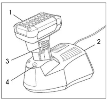
PARTS
| # | DESCRIPTION |
| 1 Battery | |
| 2 Charger | |
| 3 Battery Release | |
| 4 LED Indicator | |
FUNCTION
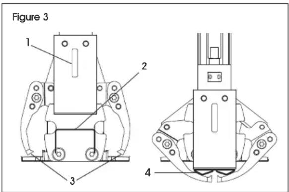
The stapling tool is positioned on carton to be closed (box detection sensors activated). (See Figure 3)
- Actuating the trigger starts the stapling process.
- During downward movement of driver blade (1), a staple (2) is sheared off the staple strip.
- The staple is pushed into the carton by the driver blade and bent (4) using the clinchers (3).
- The clinchers and driver blade are released from the carton in an upward movement and brought into the initial position.

NOTE: Three operating modes are available: Manual, Semi-automatic and Automatic
STAPLE TYPES
Staple length 5 / 8" for total carton thickness 0.20-0.35" (S-10720).
Staple length 3 / 4'' for total carton thickness 0.28-0.47" (S-10721).

NOTE: Stapler comes pre-set at 5/8" staple length.

NOTE: The staple leg length can be set.

NOTE: The staple penetration depth can be set.

NOTE: The staple clinch can be set.
SETUP CONTINUED
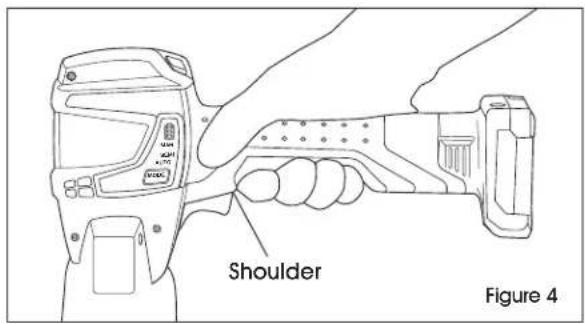
TRANSPORTING THE STAPLER
To prevent accidental triggering while carrying the tool, ensure handle is gripped by hand and index finger is behind the shoulder. (See Figure 4)
The stapler is equipped with a position guidance laser system with one front laser. (See Figure 5)
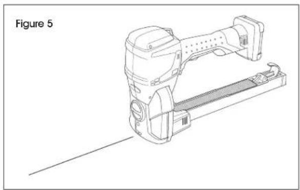

NOTE: Laser is only activated when trigger is actuated.

CAUTION! A person near the laser can feel disturbed or distracted. Do not look directly into laser or aim laser at other people.
CHARGING BATTERY

WARNING! Only use batteries and charger supplied with unit. Use of other batteries or chargers can result in injury or fire.
- Connect charger to outlet.

NOTE: When green LED illuminates, charger is ready for use.
- Insert battery in charger. (See Figure 6)
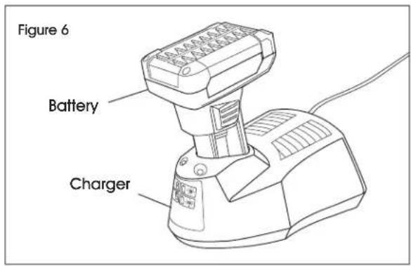

NOTE: When green LED flashes, battery is being charged.

NOTE: When green LED stays on, battery is fully charged.

NOTE: When red LED stays on, battery temperature is outside charge-temperature range.

NOTE: When red LED flashes, see operating instructions included with charger.
CHARGING TIME
- Charging of empty battery (80-100%) is approximately 1 hour.
- Ideal battery temperature during charging process is 59 - 104^ (15-40°C).
- Avoid battery temperatures below 32^ (0^) and higher than 113^ (45^) during charging.
- Battery can be charged at any time, regardless of charge status.
SETUP CONTINUED
INSERTING/REMOVING BATTERY
- Insert the charged battery into the stapler. Insert fully until the unlock buttons engage in the stapler.
- The tool status indicator, a bright blue LED, will pulse twice, indicating tool is ready to use.
- Press the unlock buttons at the same time to remove the battery.

NOTE: If the stapler is not used for approximately two minutes, it changes to sleep mode. Cancel sleep mode by actuating trigger once.

IMPORTANT! If the stapler is not used for a long period (days), the battery must be removed.
CHECKING CHARGE STATUS
LED displays battery charge status on digital user interface with battery inserted. (See Figure 7)
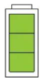
Figure 7
1234

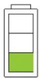
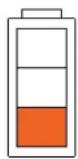
- Three bars (green) - maximum battery charge
- Two bars (green) - high battery charge
- One bar (green) - good battery charge
- One bar (red) - empty battery (battery must be charged)
OPERATING MODES
To set operating mode, press the MODE button shortly. The mode changes to MAN, SEMI or AUTO. (See Figure 8)
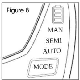
MAN (MANUAL STAPLING)
Individual staples are inserted. A cycle is initiated after the stapler is placed on the carton and the trigger is actuated manually.

NOTE: Recommended for varying (soft, hard) packaged goods.
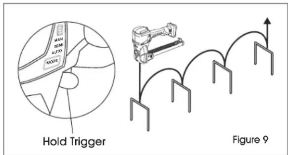
SEMI (SEMI-AUTOMATIC STAPLING)
Several staples can be inserted. Actuate trigger and hold it. As soon as the stapler is placed on a carton, a stapling cycle is activated via box detection. A new cycle is then started if the stapler is lifted off and placed back on the carton (with the trigger held continuously). (See Figure 9)

NOTE: Recommended for large quantities of identical packaged goods.
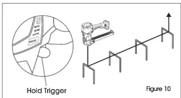
AUTO (AUTOMATIC STAPLING)
Several staples can be inserted over a predefined interval. As soon as the stapler is placed on a carton and the trigger is being actuated and held in this mode, staples will be inserted over the predefined period.
With every further actuation (and holding) of the trigger, this cycle starts anew. A maximum of 20 staples will be inserted without lifting off. (See Figure 10)

NOTE: Recommended for large quantities of identical packaged goods or long packages.
OPERATION
LOADING THE STAPLER

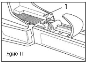
NOTE: There is a reloading arrow (1) on both sides of magazine.
(See Figure 11) If there are few staples left in the magazine, the staples should be
refilled. The correct type of staple is marked on the left side of the magazine. Use the right length of staples for application.
STOP
WARNING! Stapler can start up unexpectedly during loading. Remove battery before loading.
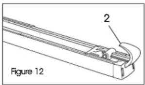
- Pull pusher (2) fully out and fix it in rear position. (See Figure 12)
- Place staple strips (3) into magazine from the top. (See Figure 13)
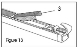

CAUTION! Danger of crushing if pusher is fed until it reaches the staples.
- Lift the pusher to release from rear position.
- Move pusher forward carefully until it reaches staples.
- Insert battery into tool.
If necessary, adjust staple length.
OPERATING STAPLER
ACTIVATING STAPLER FROM SLEEP MODE
To avoid unnecessary battery discharge, the tool switches to energy-saving mode (sleep mode) after a short period of inactivity.
- User interface goes dark (not illuminated).
- Tool status indicator is switched off.
Release safety latch and actuate trigger once.
- Sleep mode is switched off.
- Tool status indicator changes to blue and pulsates slowly.
- User interface switches on.
PRECONDITIONS
- Stapler is adjusted to correct staple length and penetration depth.
- Charged battery is inserted.
- Desired operating mode is set. The selected operating mode (default mode) is MAN (manual stapling).
STOP
WARNING! Danger of injury. User must be in a firmly balanced position when using or handling the stapler.
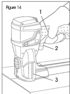
- Place stapler on carton and hold the tool against carton (box detection covered).

CAUTION! Danger of injury. Before stapling, ensure that hands and other body parts are not under tool or in carton to be closed.
2.Pull the safety latch 1. (See Figure 14)
3. Actuate the trigger (2).

NOTE: Position of tool status indicator (3) on both sides of stapler is equal to the stapling line (position).
- Move stapler and repeat until stapling is finished.
- Visually inspect the staple clinch.
OPERATION CONTINUED
CHECKING STAPLE CLINCH

WARNING! Danger of injury. Never transport or move packaged goods with improperly performed stapling. Perform staple check after each stapling.
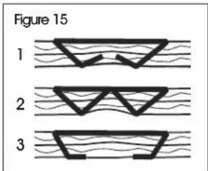
PERFORMING A STAPLE CHECK (See Figure 15)
- Good staple clinch.
- Poor staple clinch: leg length of staple too long or overbent.
- Poor staple clinch: leg length of staple too short or not bent enough.
If necessary, adjust staple clinch.
- If good stapling is not achieved, the tool must be checked by an authorized service center.

IMPORTANT! Always use original Kihlberg staples.
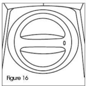
ADJUSTING PENETRATION DEPTH
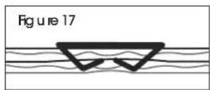
The depth of the stapling (the extent to which the driver plate penetrates the material) is easy to adjust using the setting knob. (See Figure 16)
Depress the setting knob and turn it to any of its five positions.
MIN = Lowest stapling penetration (smallest resulting leg length). (See Figure 17)
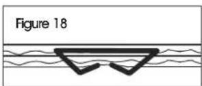
MAX = Deepest stapling penetration (longest resulting leg length). (See Figure 18)
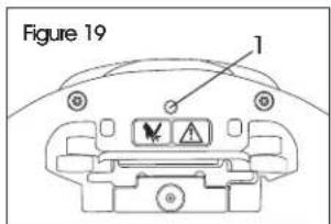
ADJUSTING STAPLE LEG LENGTH
The stapler can be adjusted to a 5 / 8'' or 3 / 4'' staple leg length.
- Remove battery from tool.
- Adjust penetration depth to deep (MAX).
- With a Torx T10 key, unscrew locking screw (1) on underside of stapler by two turns. (See Figure 19)
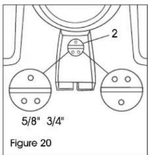
- With a screwdriver, adjust screw under penetration depth setting knob (2) to 5/8'' or 3/4'' leg length. (See Figure 20)
- Retigthen the locking screw (1).

NOTE: For 7/8" staple leg length, use 3/4" setting.
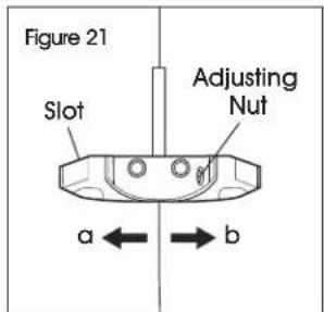
ADJUSTING STAPLE CLINCH

NOTE: It is recommended to adjust the staple clinch (how tightly the staples close).
- Remove battery from tool.
-
Remove housing plug over slot.
-
With a small screwdriver, turn the staple clinch adjusting nut behind the slot. (See Figure 21)
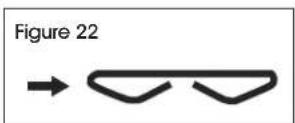
a. Turn to the right to close the clinch. (See Figure 22)
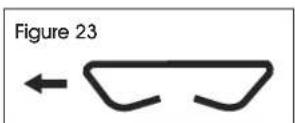
b. Turn to the left to open up the clinch. (See Figure 23)
MAINTENANCE

WARNING! Unintended actuation of trigger and safety latch during maintenance work could lead to injuries. Always remove battery before performing cleaning or preventive and corrective maintenance work.
PREVENTIVE MAINTENANCE SCHEDULE
Clean stapler weekly (for approximately 100-300 staplings per day).

NOTE: It is recommended to have stapler inspected every two years by a qualified service technician.
CLEANING THE STAPLER

NOTE: In the case of heavy dirt accumulation, it is recommended that the stapler be cleaned regularly (daily). In particular, the driver blade, the box detection and the clinchers should be checked for damage and kept clean.

CAUTION! Keep moisture away from stapler.

NOTE: After removing battery from stapler, clean the area of the clinchers, base plate, box detection and magazine with a clean rag. For better access, remove magazine. If necessary, clean/replace the driver blade/clinchers.
REMOVING JAMMED STAPLES
- Remove battery from stapler.
- Remove magazine.
- If necessary, remove rear body and/or protection plate.
- Using a pair of pliers, remove the jammed staple.
- Reinstall parts and insert battery.
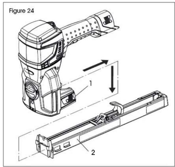
REMOVING/INSTALLING THE MAGAZINE
REMOVING
- Remove battery from stapler.
- Press quick release buttons (1) on left and right side of stapler and pull magazine (2) backward then downward. (See Figure 24)
INSTALLING
Installation is performed in reverse order.

NOTE: When installing the magazine (2), ensure quick release buttons (1) are flush with the housing. Only then is the latching of the magazine ensured and no malfunction (staple jam) can occur as a result.
MAINTENANCE CONTINUED
CLEANING/REPLACING DRIVER BLADE
| REQUIRED PARTS MFG. PART # | |
| c.561B / c.561B22 Driver Blade (wear part) 164175 | |
| M4 Torx Cylinder Screw (1) 946876 |
DISMANTLING DRIVER BLADE
- Remove battery from stapler.
- Remove magazine.
- Set penetration depth to MIN.
- Loosen six captive Torx cylinder screws (1) holding the rear body to the front section. (See Figure 25)
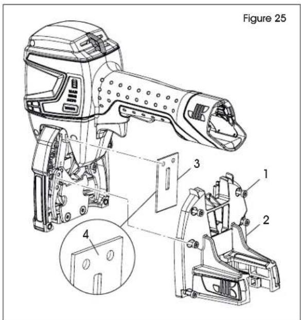
- Pull down the rear body (2) and remove it.
- Remove driver blade (3).
- Clean and check driver blade for wear. Replace if necessary.
- Fitting is performed in reverse order.
- When installing driver blade, ensure the "visible while assembling" signage (4) points outward. (See Figure 25)
CLEANING/ REPLACING CLINCHERS
| REQUIRED PARTS MFG. PART # | |
| c.561B / a.560B Clinchers (wear part) 134340 | |
| M4 Torx Cylinder Screw, Housing (1) 946876 |
DISMANTLING CLINCHERS
- Remove battery from stapler.
- Remove magazine.
- Set penetration depth to MIN.
- Loosen six captive Torx cylinder screws (1) holding the rear body to the front section. (See Figure 26)
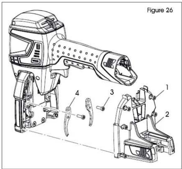
- Pull down the rear body (2) and remove it.
- Remove two Torx cylinder screws (3) and remove clinchers (4).
- Always change both clinchers at the same time.
- Clean and check clinchers for wear. Replace if necessary. (See Figure 26)
FITTING CLINCHERS
Fitting is performed in reverse order.
TROUBLESHOOTING
| OPERATING ISSUE CAUSES RECOMMENDATIONS | ||
| Battery display remains dark. | Battery faulty/fully discharged. Inserted battery not permitted (wrong battery). Battery not properly inserted. | Charge/replace battery. Insert correct battery. Check whether battery is completely inserted and unlocking device engaged. |
| User interface and tool status indicator do not react. | Sleep mode is activated. Actuate trigger. | |
| Tool status indicator red and pulsating (stapler blocked). | Process sequence warning. Actuate trigger. Remove jammed staples; see page 10. | |
| Tool status indicator pulsating quickly. | Staple encounters obstacle. Clamp does not go through carton (too hard). | Ensure that there are no obstacles. Only staple common corrugated material. |
| No stapling performed when actuating trigger. | Box detection not activated (tool not on carton). | Place tool on carton. |
| Skipping staples or intermittent feed. | Magazine not mounted correctly. Staples out of specification. Magazine quick release buttons not locked. Magazine dirty/debris inside. Driver blade/clinchers dirty/debris inside. | Install magazine; see page 10. Replace with recommended staples. Lock magazine quick release buttons. Clean magazine. Clean/replace driver blade and/or clinchers; see page 11. |
| Staple jammed in tool. Wrong staple size. Bent staples. Staples out of specification. Defective/dirty driver blade. | Replace with recommended staples. Clean/replace driver blade and/or clinchers; see page 11. | |
| Slow stapling speed or blocked. | Battery fully discharged. Carton too thick. | Charge/replace battery. Use other carton thickness. |
| Poor staple clinch. Wrong leg length setting. Wrong penetration setting. Wrong clinch setting. Driver blade/clinchers dirty/debris inside. | Adjust staple length; see page 9. Adjust penetration depth; see page 9. Adjust staple clinch; see page 9. Clean/replace driver blade and/or clinchers; see page 11. | |
TROUBLESHOOTING CONTINUED
| OPERATING ISSUE CAUSES RECOMMENDATIONS | ||
| Several staples are set at once. | Magazine not mounted correctly. Re- install magazine; see page 10. | |
| Staple penetrates only through upper corrugate. | Wrong penetration setting (too low). Staples too short. Carton too thick. | Adjust penetration depth; see page 9. Replace with longer staples. Use other carton thickness. |
| Loose staple clinch. | Clinch setting too loose. | Adjust staple clinch (tighten); see page 9. |
If the troubleshooting section does not resolve your problem, contact Uline Customer Service at 1-800-295-5510.
TECHNICAL DATA
| STAPLER SPECIFICATION | |
| Operation modes Manual/Semi-Automatic/Automatic | |
| Weight (including battery) 6 lbs. | |
| Dimensions (L x W x H) 16.1 x 4.3 x 8.1" | |
| Staple cycle speed | 200 ms |
| Magazine capacity | 150 pcs. |
| Typical measured A-rated emission sound pressure level | LFA 77 dB (A) |
| - EN 60745-1/2:2009 Average sound power level | LWA 85 dB (A) |
| - EN 60745-1/2:2009 Deviation K | KwA 2.5 dB |
| Vibrations on handle - EN 60745-1/2:2009 | ah < 2.5 m/s2 |
| Operating temperature (See also operating instructions for battery and charger on page 7) | 14-104°F |
| Maximum allowable relative humidity | Up to 90% |
| STAPLES | SPECIFICATION |
| Length | 5/8-3/4" (JK561-15/18) / 7/8" (JK561-22) |
| Width | 1¼" |
| BATTERY/CHARGER | SPECIFICATION |
| Charger type | US: Bosch BC330 (Bosch GAL 1230 CV) |
| Rated voltage charger | US: 115 V (230 V) |
| Battery | Bosch Li-Ion 12 V, 6.0 Ah |
| Charging time (80-100%) | 1 hour |
| Shots per battery charge | Up to 8,000 |