
Aeroxx 750 - Air purifier Starmix - Free user manual and instructions
Find the device manual for free Aeroxx 750 Starmix in PDF.

| Product type | Commercial air purifier |
| Brand | Starmix |
| Model | Aeroxx 750 |
| Dimensions (L x W x H) | 380 x 380 x 402 mm |
| Weight | 10.5 kg |
| Power supply | 230 V, 50/60 Hz, single-phase |
| Power consumption | 0.17 kW (ECO) / 0.25 kW (MAX) |
| Rated current | 0.94 A (ECO) / 0.9 A (MAX) |
| Maximum airflow (without hose) | 750 m³/h (MAX) |
| Minimum airflow (dirty filter) | 580 m³/h (MAX) |
| Maximum room size (15 air changes per hour, height 3 m) | 13 m² (MAX) |
| Filtration | Pre-filter + Main HEPA H13 filter (class H13) |
| Sound pressure level | 66.1 dB(A) |
| Sound power level | 79.0 dB(A) |
| Operating modes | Air recirculation, extraction (with hose), integration into a dust-proof wall |
| Intended use | Indoors only, construction sites, hotels, schools, hospitals, factories, offices |
| Volumetric flow indicator | Yes (control light) |
| Number of filtration stages | 2 (pre-filter + HEPA H13) |
| Maintenance and cleaning | Clean the housing with a damp cloth; replace the pre-filter and main filter according to the indicator |
| Safety | Grounding mandatory; do not use in explosive atmospheres; protection against hazardous dusts |
| Spare parts and repairability | Filters, hoses, power cord available via after-sales service; repairs by qualified personnel only |
| Warranty | Not specified in the manual |
Frequently Asked Questions - Aeroxx 750 Starmix
User questions about Aeroxx 750 Starmix
0 question about this device. Answer the ones you know or ask your own.
Ask a new question about this device
Download the instructions for your Air purifier in PDF format for free! Find your manual Aeroxx 750 - Starmix and take your electronic device back in hand. On this page are published all the documents necessary for the use of your device. Aeroxx 750 by Starmix.
USER MANUAL Aeroxx 750 Starmix
natural_image
Exterior view of a black starmix electric heater with red control knobs and power lines (no readable text or symbols beyond branding)Bedienungsanleitung (original)
Operating instructions
natural_image
Technical line drawing of a mechanical housing component with labeled parts (no text or symbols present)

natural_image
Technical line drawing of a mechanical device with coiled spring and fan assembly (no text or symbols)natural_image
Line drawing of a portable industrial machine with coiled tubing and ventilation slots (no text or symbols)natural_image
Technical line drawing of a washing machine with circular components and fan base (no text or symbols)natural_image
Technical line drawing of a multi-tiered industrial air conditioning unit with internal components and a magnified inset showing internal structure detail (no text or labels)natural_image
Technical line drawing of a mechanical device with fan and housing (no text or symbols)natural_image
Technical line drawing of an electrical outlet with coiled wires and a connector (no text or symbols)natural_image
Technical line drawing of a circular mechanical component with mounting brackets (no text or symbols)Read the operating instructions carefully before using the air cleaner. The operating instructions provide important information on safety, commissioning, operation, maintenance and care. Keep the operating instructions in a safe place and pass them on to the next owner if you sell it.
The manufacturer reserves the right to make design and specification changes.
1 Symbols and signs used
| Symbol / Signal word | Description |
| This is the warning symbol. It alerts to the potential risk of injuries. Observe all instructions with this symbol to avoid injuries or even death. The warning symbol is always accompanied by the signal words DANGER, WARNING and CAUTION. | |
| DANGER! | Indicates a high risk hazard which will result in death or serious injuries unless averted. |
| WARNING! | Indicates a moderate risk hazard which may result in death or serious injuries unless averted. |
| CAUTION! | Indicates a low risk hazard which may result in mild or moderate injuries unless averted. |
| NOTE Indicates | advice or instructions which facilitate work and ensure safe operation. |
| Indicates a requirement which must be met before carrying out an action. | |
| Indicates actions which must be carried out by the user in succession. | |
| Indicates the result of an action. |
2 Safety
2.1 Important safety instructions
▶ Observe the accident prevention regulations applicable in your country.
If the product is used in conjunction with a power tool, read the operating instructions for the power tool before use and comply with all the instructions and warnings.
WARNING!
Hazard due to an electric shock
Damaged or altered electrical parts may lead to an electric shock when touched.
- Do not use the device if plug and outlet do not match. Do not change the plug in any way. Do not use adapters with grounded devices!
- Insert the plug in a suitable earthed/grounded power outlet which has been correctly and safely installed and is in compliance with local regulations. If you are in doubt about the effectiveness of the power outlet's earth/ground connection, have it checked by a qualified specialist.
- Check the appliance's supply cord at regular intervals. Do not use the device with a damaged supply cord or plug, but return it to the manufacturer for examination and/or repair.
Do not lay the supply cord under carpeting, furniture or other appliances. Do not cover the cord with throw rugs, runners or similar coverings. Arrange the supply cord away from traffic areas and ensure that the supply cord does not cause tripping hazards.
- Keep the supply cord away from heat, oil, sharp edges and moving parts.
▶ Do not lay the supply cord in or through a puddle of water.
▶ Do not use the supply cord for carrying, hanging up or unplugging the device.
- Do not touch the supply cord or extension cord if they are damaged while working. Disconnect the supply cord plug from the power outlet.
The electric supply cord or extension cord may be replaced only with a cord of the type specified in the operating instructions.
▶ Do not expose the device to rain or moisture.
▶ Never operate the device when it is dirty or wet. Dust from conductive materials or water on the surface of the device may lead to an electric shock. Have dirtied or dusty products checked at regular intervals by starmix service, especially if they are used frequently for working on conductive materials.
In the event of an interruption in the electric supply, switch the product off and unplug it from the power outlet.
▶ Always switch the product off at the main switch! The start-up capacitor can carry an electrical charge even after the plug has been disconnected from the power outlet.
WARNING!
Explosion and fire hazard
Sucking in flammable substances or overheated components may cause the device to catch fire. Risk of burns or injury from flying parts.
- Do not use the product to filter hot or incandescent fragments or particles. Make sure that the temperature of the inducted contaminated air does not exceed 60^ (140 °F).
The following materials must not be sucked into the device:
- flammable or explosive solvents
• substances impregnated with solvent - explosive dusts
• liquids such as petrol, oil, alcohol, thinner
• materials and shavings hotter than 60 °C
- Do not operate the product in explosive atmospheres, such as in the presence of flammable liquids, gases, aerosols or dust. Electric appliances cause sparks which may ignite the dust or fumes.
WARNING!
Risk of overheating!
When using the appliance with unsuitable supply cords it may suffer a drop in performance and the extension cord may overheat.
▶ Use only extension cords of a type approved for the application.
- Do not touch the supply cord or extension cord if it is damaged while work is in progress. Disconnect the supply cord plug from the power outlet.
- Check the appliance's supply cord at regular intervals and replace it if it is damaged.
WARNING!
Health hazard due to hazardous dusts
Inhalation of hazardous dusts can lead to serious lung diseases.
▶ Do not operate the device in an environment containing asbestos.
▶ Wear suitable personal protective equipment:
• respiratory protection appropriate for the dust load.
- eye protection
- ear protection
- protective gloves
- protective footwear
If devices are provided for the connection of dust extraction and collection facilities, ensure these are connected and properly used. Use of a vacuum cleaner can reduce dust-related hazards.
▶ Ensure sufficient ventilation of the workplace.
▶ Clean the maintenance area after the work.
⚠ WARNING!
Danger due to improper maintenance, repair and cleaning
Equipment that is not properly maintained and repaired poses a danger to the user.
When using in food processing facilities: Clean and disinfect the device immediately after use to prevent contamination.
▶ Do not use flammable cleaning agents.
▶ Do not clean with steam jet equipment or high-pressure cleaners.
▶ Only use genuine starmix accessories and spare parts or those of equivalent quality.
▶ Operate the device only with approved filters.
Do not permit the product to become overloaded or blocked because of an overfilled filter. As soon as the filter control light shows, stop working with the device. Find the cause and change the filters if necessary.
▶ Do not allow water to collect in the hollow of the grip.
WARNING!
Risk of injury due to improper handling
▶ Do not leave the device unattended.
▶ Never stand or sit on the device.
▶ Only place the device on horizontal surfaces.
▶ Make sure that the product is so steady that there is no risk of it tipping over.
- Do not stand on the product (do not use it as a substitute for a ladder).
Risk of falling when working on stairs. Ensure secure footing.
▶ Ensure that the workplace is well lit.
- Avoid tilting or moving the product while it is in operation. The flow of air from the air discharge can swirl dust off the floor if the flow of air is directed toward the floor.
▶ Do not use the device or its accessories in the following cases:
• Device is visibly damaged, e. g. cracks in the housing, damage from sharp edges.
• If hidden defects are suspected, e. g. after falling
▶ Do not transport the product by crane or with hoists.
- Avoid unusual body positions. Keep proper footing and balance at all times.
- Keep the work area clean and uncluttered and watch out for supply cords routed in the work area. Carelessly routed supply cords can constitute trip hazards and lead to injuries.
WARNING!
Danger due to human error
This appliance can be used by children aged from 8 years and above and persons with reduced physical, sensory or mental capabilities or lack of experience and knowledge if they have been given supervision or instruction concerning use of the appliance in a safe way and understand the hazards involved.
▶ Children shall not play with the appliance.
- Cleaning and user maintenance shall not be made by children without supervision.
CAUTION!
Possible risk of injury from working with a defective device
▶ Switch the air cleaner off immediately if you detect a defect.
▶ Do not operate a defective device.
CAUTION!
Suffocation hazard
- Do not let children play with consumable or packaging material, e.g. plastic bags.
▶ Do not let children play with small parts.
2.2 Intended use
The product described is an air cleaner for removing fine dust particles from room air. It is equipped with an H13 HEPA air filter.
The product is designed for the commercial sector, e.g. for use on construction sites, in hotels, schools, hospitals, factories, stores and offices, and by rental companies. The product was developed for use in dry rooms where there is no risk of explosion.
The product is intended for indoor use only.
Several devices can be connected in series to achieve a volume flow that is sufficient for the room volume.
Proper use also includes:
- Read and understand safety instructions
- Observe operating instructions
- Observe inspection and maintenance conditions
- Observe all national safety regulations
2.3 Reasonably foreseeable use (misuse)
DO NOT USE in environments containing the following substances:
- Dusts with asbestos contamination
- Hot or incandescent fragments or particles. The temperature of the inducted contaminated air must not exceed 60 °C (140 °F).
- Substances impregnated with solvent
- In potentially explosive environments; such as in the presence of flammable liquids, gases or dust.
Any application other than those described in chapter 2.2 is not permitted. This includes in particular:
- Use in environments containing the materials excluded above
- Non-compliance with the operating instructions
- Use by unsuitable persons (under 18 years of age, persons under the influence of drugs)
- Insufficient or improper maintenance and servicing
- Use of unsuitable consumable materials
- Making alterations to the product.
The consequences of these reasonably foreseeable applications may include:
- Fire or explosion of the air cleaner, with consequent risk to the operator due to burns or flying parts, inhalation of potentially toxic substances
- When the air cleaner sucks in asbestos, there is danger to the operator or other persons in the vicinity through inhalation of harmful substances.
2.4 Ambient conditions
Temperature range -10^ to +40^
Humidity range only dry rooms
Explosion protected area not allowed
3 Initial Use
3.1 Unpacking
- Verify the contents are complete and check for transport damage when unpacking the device.
4 Preparing for operation
WARNING!
Risk of electric shock caused by missing grounding!
▶ Only use antistatic equipment.
4.1 Checking the product and the fi Iters
▶ Check all visible parts and controls for signs of damage at regular intervals and make sure that they all function correctly.
▶ Make sure that both filters are inserted (14 and 15).
▶ Check all fi Iters and seals and replace damaged fi Iters (see chapter 6.2). Operate the product only with approved fi Iters installed (pre-fi Iters and main fi Iters).
- Do not operate the product if signs of damage are found or if parts malfunction. Have it repaired immediately by starmix service.
▶ Make sure that all parts of the air cleaner are clean and dry.
4.2 Operation modes
The air cleaner can be used in two operating modes:
4.2.1 Air recirculation operation
Dusty air is sucked in and filtered before being released back into the room.
4.2.2 Vacuum operation
NOTE
Working with the hose changes the volume flow – the "Volume flow" control light may come on.
The product can also be operated in combination with hoses or a dust protection wall to give you more control about the air inlet and outlet.
The product does not have to be placed in the room itself.
Options for vacuum operation:
- with air inlet hose
- with air outlet hose
- with air inlet and air outlet hose
- integrated in dust protection wall
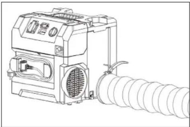
4.3 Connecting the hoses
NOTE
Working with the hose changes the volume flow.
▶ Lay the hose as straight as possible.
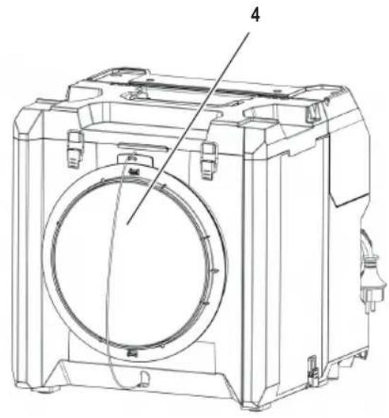
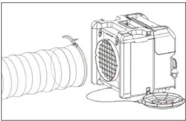
Remove the air inlet cover (4).
- Attach the air inlet hose to the air inlet (13) and secure it with the toggle catch.
natural_image
Technical line drawing of a mechanical device with coiled spring and fan assembly (no text or symbols)Fig. 1: Connecting the air inlet hose
- Attach the air outlet hose to the air outlet (7) and secure it with the toggle catch.

natural_image
Line drawing of a portable industrial machine with coiled tubing and ventilation slots (no text or symbols)Fig. 2: Connecting the air outlet hose
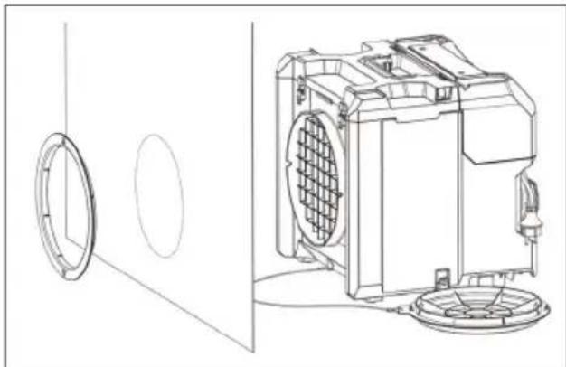
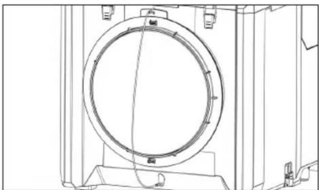
4.4 Integration into a dust-protection wall
You can integrate the product directly into a dust-protection wall with the adapter for dust-protection wall and vacuum dust out of the inside of the dust-protection wall without the product being directly in the room.
▶ Pull the adapter for dust-protection wall (12) off the air inlet cover (4).
▶ Position the product at the dust-protection wall.
▶ Turn the adapter for dust-protection wall 180^ so that the inner ring fi ts into the air inlet (13).
Use the adapter for dust-protection wall to secure the dust-protection wall to the air inlet.
If necessary, cut an opening into the dust-protection wall secured to the air inlet.
natural_image
Technical line drawing of a washing machine with circular components and fan base (no text or symbols)Fig. 3: Adapter for dust-protection wall
4.5 Using multiple devices in parallel
NOTE
The socket is under constant current.
▶ Observe the total power of the socket.
To increase the cleaning effect, several appliances can be operated in parallel. This can be done by distributing them around the room or stacking them.
4.5.1 Distributing
▶ Distribute several devices in the room.
▶ Connect them with the mains cables.
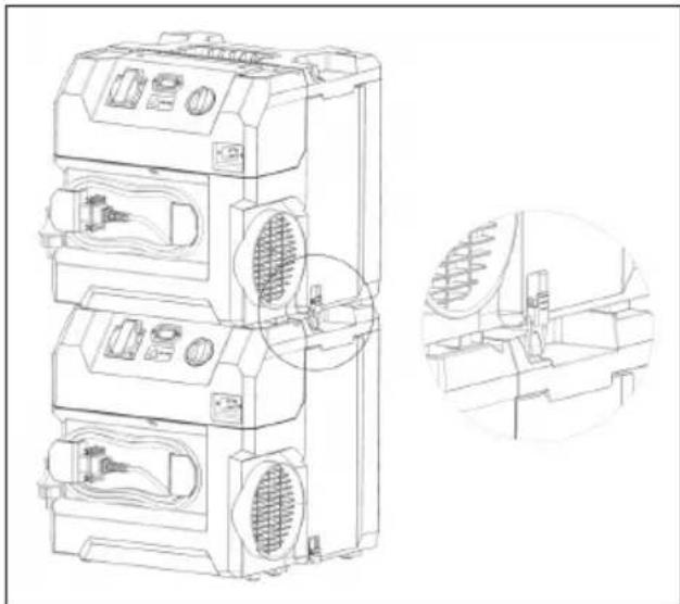
4.5.2 Stacking
▶ Stack several devices on top of each other.
▶ Secure them together with the toggle catches (3).
▶ Use the socket on the control panel for series power supply.
- Connect them in series with the mains cables.
natural_image
Technical line drawing of a multi-tiered industrial air conditioner unit with internal fan and ventilation slots, plus an inset close-up of the internal structure (no text or symbols)Fig. 4: Stacking several devices
5 Operation
5.1 Air cleaning
⚠ WARNING!
Health hazard due to hazardous dusts!
▶ Observe the safety instructions in chapter 2.
WARNING!
Risk of fi re! Explosion hazard! Risk of electric shock!
▶ Observe the safety instructions in chapter 2.
The optimum cleaning power is achieved with no hoses attached to the air cleaner. Depending on the conditions and the application, you can connect an intake hose or position the product directly in a dust-protection wall (see chapter 4.4).
The product has two air-cleaning stages. In operation, use stage 'MAX' with the higher cleaning power. The 'ECO' setting is only for post-cleaning the air. It can be activated when the room is unoccupied.
5.1.1 Switching on the device
CAUTION!
Health hazard due to hazardous dusts!
When the product starts up, it produces a strong current of discharged air. This can swirl up dust in the product's immediate vicinity.
- Avoid tilting or moving the product while it is in operation.
▶ Connect the device to the power supply.
▶ Make sure that the product is steady and cannot topple.
Remove the air inlet cover (4).
▶ Turn the main switch (11) to the 'MAX' position (full power).
5.1.2 Keep an eye on the "Volume flow" control light
If the control light lights up, check the filters as described in 6.2 and replace them if necessary.
If the control light continues to illuminate after this, see chapter 9 for troubleshooting.
5.1.3 Finishingwork
▶ Turn the main switch to the 'OFF' position.
Before you unplug the supply cord of a power tool from the product's electric tool power outlet, always first disconnect the product from the main electricity supply.
▶ Store the cable.
▶ Close the air inlet cover.
6 Cleaning and Maintenance
WARNING!
Risk of electric shock!
Attempting cleaning and maintenance with the supply cord connected to a power outlet can lead to severe injury and burns. Conductive dust on the housing can lead to an electric shock.
▶ Always unplug the supply cord before carrying out cleaning and maintenance tasks.
Before you open the filter cover, wait until the turbine has come to a complete stop.
6.1 Cleaning
WARNING!
Danger due to improper cleaning!
Equipment that is not properly maintained poses a danger to the user.
When using in food processing facilities: Clean and disinfect the air cleaner immediately after use to prevent contamination.
▶ Do not use fl ammable cleaning agents.
- Do not clean with steam jet equipment or high-pressure cleaners.
NOTE
Acid, acetone, silicone and solvents can damage the air cleaner.
- Clean the casing of the air cleaner with an only slightly damp cloth.
▶ Always clean the air cleaner when it appears dirty from the outside.
▶ Carefully remove stubborn dirt from the tool.
▶ Clean the air vents carefully with a dry brush.
▶ Clean the casing with an only slightly damp cloth.
6.2 Replacing the air fi Iters
WARNING!
Danger due to hazardous dusts!
Inhalation of hazardous dusts can lead to serious lung diseases.
▶ Wear suitable personal protective equipment, such as
• respiratory protection appropriate for the dust load
- eye protection
- protective gloves
6.2.1 Intervals for fi Iter replacement
NOTE
An overfi lled fi iter can cause overload or blockage of the product
As soon as the "Volume flow" control light shows, stop working with the product.
▶ Find the cause and change the filters if necessary.
- Replace the main fi Iter (15) as soon as the "Volume flow" control light shows again after changing the pre-fi Iter.
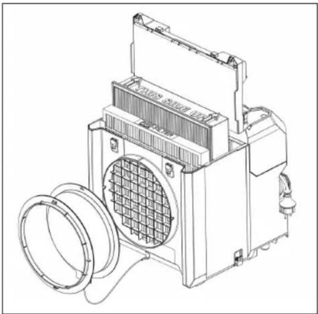
6.2.2 Replacing the fi Iters
▶ Switch the product off and wait until the turbine runs down to acomplete stop.
- Open both toggle catches and remove the filter cover (16) by lifting it up.
▶ Remove the pre-fi iter or main fi iter.
Remove heavy accretions of dust inside the housing with a vacuum cleaner.
NOTE
▶ Ascertain the dust class of the dust and use a vacuum cleaner approved for the dust class.
Insert a new pre-fi iter or main fi iter as shown in Fig. 5.
NOTE
The device will only work properly when the filters are inserted correctly.
▶ Make sure the position of the filters is correct.
▶ Lower the filter cover into position and seal the it by closing the toggle catches.
natural_image
Technical line drawing of a mechanical device with fan and housing (no text or symbols)Fig. 5: Replacing the filters
7 Transport and storage
7.1 Transport
Remove all accessories e.g. hoses before transport.
▶ Make sure that the device is securely fastened during the entire transport.
▶ After transport inspect the air cleaner for signs of damage and verify that all visible parts function correctly.
- Store the cable in the storage position (Fig. 6). Secure the plug with the cable clip provided.
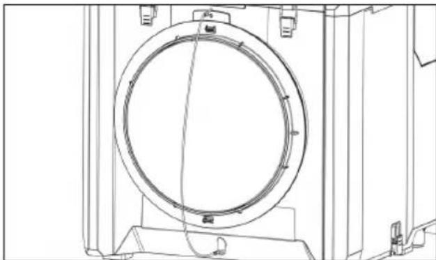
▶ Close the air inlet cover (Fig. 7) prior to transport. This prevents dust from escaping from the device into the environment.
7.2 Storage
▶ Always store this product with the electric supply cable unplugged from the electricity supply.
- Store this product in a dry place, where it cannot be accessed by children or unauthorized persons.
▶ After a long period of storage, always inspect the air cleaner for signs of damage and verify that all visible parts function correctly.
natural_image
Technical line drawing of an electrical connector with coiled wires and a terminal block (no text or symbols)Fig. 6: Storage position of the cable
natural_image
Technical line drawing of a circular mechanical component mounted on a base frame (no text or symbols)Fig. 7: Air inlet cover (closing position)
8 Further information
For more information, scan the QR code on the front of the device.

9 Troubleshooting and repairs
WARNING!
Risk of electric shock!
▶ Repairs to the electrical section of the tool or appliance may be carried out only by trained electrical specialists.
WARNING!
Improperly repaired air cleaners pose a danger to the user!
▶ Repairs should only be carried out by qualified personnel, e.g. customer service.
▶ Only use original spare parts.
NOTE
Malfunctions are not always due to defects of the air cleaner.
| Trouble or fault Possible cause Action to be taken | ||
| The product cannot be switched on. | The supply cord is not plugged in correctly. | Plug the supply cord into the power outlet. |
| The supply cord or plug is defective. Contact starmix service. | ||
| There is dust in the discharged air. | The filter seal of the filter is damaged. | Replace the filter and clean the interior of the product. |
| There are holes in the filter. Replace the filter and clean the interior of the product. | ||
| The “Volume flow” control light comes on. The filter is clogged. Check the filters and replace them if necessary. | ||
| The air inlet or outlet grid is blocked. Clean the air inlet or outlet grid and remove the blockage. | ||
| The air inlet or outlet grid is blocked. Clean the air inlet or outlet grid and remove the blockage. | ||
| The “Volume flow” control light comes on after replacement of the pre-filter. | The main filter is clogged. Replace the main filter. If the filter control light comes on despite these measures, contact starmix service. | |
| The pre-filter is inserted incorrectly. | Check the filters and insert them correctly, if necessary. | |
| The filter cover is open. | Close the filter cover. | |
10 Original parts
NOTE
Only use original accessories.
| Article description Special features / material Order No. | ||
| Main fi lter H13 HEPA 466101 | ||
| Pre-fi lter 5 pcs 466118 | ||
| Air inlet hose 6 m 466125 | ||
| Air outlet hose 6 m 466163 | ||
| Set power cord 466132 |
Further accessories can be found in the special accessories list, these are available on request from the starmix service team or online at: www.starmix.de, e-mail: info@starmix.de.
11 Disposal
Waste equipment contains valuable materials which can be reprocessed.
Do not dispose of the device as regular household waste.
Properly dispose through a suitable collection point, e. g. at your municipal disposal site.
12 Specifications
| Type Aeroxx 750 | Unit | ECO | MAX |
| Weight | kg | 10,5 | |
| Dimensions L x W x H | mm | 380 x 380 x 402 | |
| Power rating | kW | 0,17 0,25 | |
| Voltage | V | 230 (50/60 Hz) | |
| Current | A | 0,94 | 0,9 |
| Power source | 1-phase | ||
| Power rating EU socket | A | 11 | |
| W | 3200 | ||
| Main fi Iter (HEPA H13) | m2 | 2,83 | |
| Pre-fi Iter | m2 | 0,35 | |
| Mains cable | H07RN-F 3G1.5, L=3m | ||
| Max. volume flow rate(without hoses installed, unused fi Iter) | m3/h | 580 | 750 |
| Min. volume flow rate(fi Iter with dust, the moment the fi Iter control light comes on) | m3/h | 400 | 580 |
| Max. room size (15 air changes / h, room height 3 m) | m2 | 9 | 13 |
| Max. volume flow rate (turbine) | m2/h | 1425 | |
| Max. vacuum | Pa | 190 | 250 |
| Sound power level | dB(A) | 79,0 | |
| Sound pressure level | dB(A) | 66,1 | |
| Uncertainty | dB(A) | ±3 | |
13 EC Declaration of conformity
We declare that the machine described below complies with the relevant basic safety and health requirements of the EU Directives, both in its basic design and construction as well as in the version put into circulation by us. This declaration shall cease to be valid if the machine is modified without our prior approval.
Product: Commercial Air cleaner
Type:
Aeroxx 750
The design of the devices complies with the following relevant regulations:
EC-Machinery Directive 2006/42/EG
EMC-Directive 2014/30/EU
ROHS 2011/65/EU
EC Machinery Directive 2006/42/EC including amendments:
EN 60335-1:2012/A15:2021
EN 60335-2-65:2003/A11:2012
EN 62233:2008
EC Directive EMC 2014/30/EU
EN 55014-2:2021
EN 55014-1:2021
EN 61000-3-2:2019/A1:2021
EN 61000-3-3:2013/A2:2021
RoHS 2011/65/EU
EN 63000:2018
Authorised representative for the compilation of the technical documentation:
ELECTROSTAR GmbH, Hans-Zinser-Str. 1-3, 73061 Ebersbach/Fils, Germany
Candu Sore
30.07.2024
Carsten Gresser
Head of Quality Assurance
Français
natural_image
Technical line drawing of a mechanical device with coiled tubing and a fan-like housing (no text or symbols)natural_image
Line drawing of a portable air conditioner unit with coiled tubing and ventilation slots (no text or symbols)natural_image
Technical line drawing of a washing machine with circular components and fan base (no text or symbols)natural_image
Technical line drawing of a multi-tiered industrial device with ventilation grilles and internal components, shown in two orthographic views (no text or labels)natural_image
Technical line drawing of a mechanical device with fan and housing (no text or symbols)Fig. 5: Remplacement des fi Itres
natural_image
Technical line drawing of an electrical outlet with coiled wires and a connector (no text or symbols)natural_image
Technical line drawing of a circular mechanical component with mounting brackets (no text or symbols)natural_image
Technical line drawing of a mechanical device with coiled spring and fan assembly (no text or symbols)natural_image
Line drawing of a mechanical device with coiled tubing and ventilation slots (no text or symbols)natural_image
Technical line drawing of a washing machine with circular components and fan base (no text or symbols)natural_image
Technical line drawing of a multi-tiered industrial air conditioning unit with internal components and ventilation ducts (no text or labels)natural_image
Technical line drawing of a mechanical device with fan and housing (no text or symbols)Fig. 5: De fi Iters vervangen
7 Transport en opslag
7.1 Transport
natural_image
Technical line drawing of an electrical outlet with coiled wires and a connector (no text or symbols)natural_image
Technical line drawing of a circular mechanical component with mounting brackets and internal structure (no text or symbols)9 Problemen oplossen en reparaties
⚠ WAARSCHUWING!
natural_image
Technical line drawing of a mechanical device with coiled spring and fan assembly (no text or symbols)natural_image
Line drawing of a mechanical device with coiled tubing and ventilation slots (no text or symbols)natural_image
Technical line drawing of a washing machine with circular components and fan base (no text or symbols)natural_image
Technical line drawing of a multi-tiered industrial air conditioner unit with internal components and a magnified inset showing internal structure (no text or labels)natural_image
Technical line drawing of a portable air conditioner unit with cooling fan and ventilation cover (no text or symbols)natural_image
Technical line drawing of an electrical outlet with coiled wires and a connector (no text or symbols)natural_image
Technical line drawing of a circular mechanical component with mounting brackets and internal structure (no text or symbols)natural_image
Technical line drawing of a mechanical device with coiled spring and fan assembly (no text or symbols)natural_image
Line drawing of a portable industrial machine with coiled tubing and ventilation slots (no text or symbols)natural_image
Technical line drawing of a mechanical device with circular components and a fan-like base (no text or symbols)natural_image
Technical line drawing of a multi-tiered industrial air conditioning unit with internal components and a close-up inset showing internal structure (no text or labels)Fig. 4: Apilar varios aparatos
5 Funcionamiento
natural_image
Technical line drawing of a mechanical device with a coiled spring and fan (no text or symbols)natural_image
Technical line drawing of an electrical connector with coiled wires and a terminal block (no text or symbols)natural_image
Technical line drawing of a circular mechanical component with mounting brackets and internal structure (no text or symbols)4.3 Ligar as mangueiras
NOTA
natural_image
Technical line drawing of a mechanical device with coiled spring and fan assembly (no text or symbols)Fig. 1: Ligar a mangueira de entrada de ar
Ligue a mangueira de saída de ar à saída de ar (7) e fi xe-a com o fecho de báscula.
natural_image
Line drawing of a portable industrial machine with coiled tubing and ventilation slots (no text or symbols)Fig. 2: Ligar a mangueira de saída de ar
natural_image
Technical line drawing of a mechanical device with circular components and fan-like structure (no text or symbols)natural_image
Technical line drawing of a multi-tiered industrial air conditioning unit with internal components and ventilation ducts (no text or labels)natural_image
Technical line drawing of a mechanical device with fan and housing (no text or symbols)natural_image
Technical line drawing of an electrical outlet with coiled wires and a connector (no text or symbols)natural_image
Technical line drawing of a circular mechanical component with mounting brackets and internal structure (no text or symbols)natural_image
Technical line drawing of a mechanical device with coiled tubing and a fan-like housing (no text or symbols)natural_image
Line drawing of a portable industrial machine with coiled tubing and ventilation slots (no text or symbols)natural_image
Technical line drawing of a mechanical device with circular components and a fan-like structure (no text or symbols)natural_image
Technical line drawing of a multi-tiered industrial air conditioner unit with internal components and a close-up inset showing internal structure (no text or labels)natural_image
Technical line drawing of a mechanical device with fan and housing (no text or symbols)natural_image
Technical line drawing of an electrical outlet with coiled wires and connectors (no text or symbols)natural_image
Technical line drawing of a circular mechanical component with mounting brackets and internal structure (no text or symbols)Fig. 7: Luftintagslock(stängningsläge)
8 Ytterligare information
natural_image
Technical line drawing of a mechanical device with coiled tubing and a fan-like housing (no text or symbols)natural_image
Line drawing of a mechanical device with coiled tubing and control panel (no text or symbols)natural_image
Technical line drawing of a washing machine with circular components and fan base (no text or symbols)natural_image
Technical line drawing of a multi-tiered industrial air conditioner unit with internal components and a magnified inset showing internal structure (no text or labels)Fig. 4: Useiden laitteiden pinoaminen
5 Operaatio
5.1 Ilman puhdistus
⚠️ VAROITUS!
natural_image
Technical line drawing of a mechanical device with fan and housing (no text or symbols)natural_image
Technical line drawing of an electrical outlet with coiled wires and connectors (no text or symbols)natural_image
Technical line drawing of a circular mechanical component with mounting brackets and internal structure (no text or symbols)Fig. 7: Ilmanottoaukon kansi (sulkuasento)
8 Lisätietoja
Fare for overoppheting!
natural_image
Technical line drawing of a mechanical device with coiled spring and fan assembly (no text or symbols)Fig. 1: Koble til luftinntaksslangen
natural_image
Line drawing of a portable industrial machine with coiled tubing and ventilation slots (no text or symbols)natural_image
Technical line drawing of a washing machine with circular components and fan base (no text or symbols)Fig. 3: Adapter for støvbeskyttelsesvegg
4.5 Bruk fl ere enheter parallelt
MERK F∅LGENDE
natural_image
Technical line drawing of a multi-tiered industrial air conditioning unit with fan and vent slots, shown in two orthographic views (no text or labels)natural_image
Technical line drawing of a mechanical device with fan and housing (no text or symbols)Fig. 5: Bytte ut fi ltrene
natural_image
Technical line drawing of an electrical outlet with coiled wires and a connector (no text or symbols)natural_image
Technical line drawing of a circular mechanical component mounted on a frame (no text or symbols)Fig. 7: Luftinntaksdeksel(lukkestilling)
natural_image
Technical line drawing of a mechanical device with coiled spring and fan assembly (no text or symbols)natural_image
Line drawing of a mechanical device with coiled tubing and ventilation slots (no text or symbols)natural_image
Technical line drawing of a washing machine with circular components and fan base (no text or symbols)natural_image
Technical line drawing of a multi-tiered industrial air conditioner unit with internal components and a close-up inset showing internal structure (no text or labels)natural_image
Technical line drawing of a mechanical device with a circular component and fan (no text or symbols)natural_image
Technical line drawing of an electrical outlet with coiled wires and connectors (no text or symbols)Fig. 6: Opbevaringsposition for kablet
natural_image
Technical line drawing of a circular mechanical component mounted on a base frame (no text or symbols)natural_image
Technical line drawing of a mechanical device with coiled tubing and a fan-like housing (no text or symbols)natural_image
Line drawing of a mechanical device with coiled tubing and control panel (no text or symbols)natural_image
Technical line drawing of a washing machine with circular components and fan base (no text or symbols)natural_image
Technical line drawing of a multi-tiered industrial air conditioner unit with internal components and a close-up inset showing internal structure (no text or labels)natural_image
Technical line drawing of a mechanical device with fan and housing (no text or symbols)natural_image
Technical line drawing of an electrical outlet with coiled wires and a connector (no text or symbols)natural_image
Technical line drawing of a circular mechanical component with mounting brackets (no text or symbols)natural_image
Technical line drawing of a mechanical device with coiled tubing and a fan-like housing (no text or symbols)natural_image
Line drawing of a portable industrial machine with coiled tubing and ventilation slots (no text or symbols)natural_image
Technical line drawing of a mechanical device with circular components and a fan-like structure (no text or symbols)natural_image
Technical line drawing of a multi-tiered industrial air conditioner unit with internal components and a close-up inset showing internal structure (no text or labels)natural_image
Technical line drawing of a mechanical device with a coiled spring and fan (no text or symbols)natural_image
Technical line drawing of an electrical outlet with coiled wires and connectors (no text or symbols)natural_image
Technical line drawing of a circular mechanical component mounted on a base frame (no text or symbols)natural_image
Technical line drawing of a mechanical device with coiled spring and fan assembly (no text or symbols)natural_image
Line drawing of a mechanical device with coiled tubing and ventilation slots (no text or symbols)natural_image
Technical line drawing of a mechanical device with circular components and fan-like structure (no text or symbols)natural_image
Technical line drawing of a multi-tiered industrial air conditioner unit with internal components and a magnified inset showing internal structure (no text or labels)Fig. 4: Stivuirea mai multor dispositive
5 Operatiunea
natural_image
Technical line drawing of a portable air conditioner unit with cooling fan and ventilation cover (no text or symbols)natural_image
Technical line drawing of an electrical outlet with coiled wires and connectors (no text or symbols)natural_image
Technical line drawing of a circular mechanical component with mounting brackets and internal structure (no text or symbols)natural_image
Technical line drawing of a mechanical device with coiled tubing and a fan-like housing (no text or symbols)natural_image
Line drawing of a mechanical device with coiled tubing and control panel (no text or symbols)natural_image
Technical line drawing of a washing machine with circular components and fan base (no text or symbols)natural_image
Technical line drawing of a multi-tiered industrial air conditioner unit with internal components and a close-up inset showing internal structure (no text or labels)natural_image
Technical line drawing of a mechanical device with fan and housing (no text or symbols)natural_image
Technical line drawing of an electrical outlet with coiled wires and a connector (no text or symbols)natural_image
Technical line drawing of a circular mechanical component with mounting brackets and internal structure (no text or symbols)natural_image
Technical line drawing of a mechanical device with coiled spring and fan assembly (no text or symbols)natural_image
Line drawing of a mechanical device with coiled tubing and ventilation slots (no text or symbols)natural_image
Technical line drawing of a mechanical device with circular components and a fan-like base (no text or symbols)natural_image
Technical line drawing of a multi-tiered industrial air conditioning unit with internal components and a close-up inset showing internal structure (no text or symbols)natural_image
Technical line drawing of a mechanical device with fan and housing (no text or symbols)natural_image
Technical line drawing of an electrical outlet with coiled wires and connectors (no text or symbols)natural_image
Technical line drawing of a circular mechanical component mounted on a base frame (no text or symbols)


- Safety
- Important safety instructions
- WARNING!
- Hazard due to an electric shock
- Explosion and fire hazard
- Risk of overheating!
- Health hazard due to hazardous dusts
- ⚠ WARNING!
- Danger due to improper maintenance, repair and cleaning
- Risk of injury due to improper handling
- Danger due to human error
- CAUTION!
- Possible risk of injury from working with a defective device
- Suffocation hazard
- Intended use
- Reasonably foreseeable use (misuse)
- Ambient conditions
- Initial Use
- Unpacking
- Preparing for operation
- Checking the product and the fi Iters
- Operation modes
- Air recirculation operation
- Vacuum operation
- NOTE
- Connecting the hoses
- Integration into a dust-protection wall
- Using multiple devices in parallel
- Distributing
- Stacking
- Operation
- Air cleaning
- Switching on the device
- Keep an eye on the "Volume flow" control light
- Finishingwork
- Cleaning and Maintenance
- Risk of electric shock!
- Cleaning
- Danger due to improper cleaning!
- Replacing the air fi Iters
- Danger due to hazardous dusts!
- Intervals for fi Iter replacement
- Replacing the fi Iters
- Transport and storage
- Transport
- Storage
- Further information
- Troubleshooting and repairs
- Improperly repaired air cleaners pose a danger to the user!
- Original parts
- Disposal
- Specifications
- EC Declaration of conformity
- Français
- Transport en opslag
- Problemen oplossen en reparaties
- ⚠ WAARSCHUWING!
- Funcionamiento
- Ligar as mangueiras
- NOTA
- Ytterligare information
- Operaatio
- Ilman puhdistus
- ⚠️ VAROITUS!
- Lisätietoja
- Fare for overoppheting!
- Bruk fl ere enheter parallelt
- MERK F∅LGENDE
- Operatiunea
Brand : Starmix
Model : Aeroxx 750
Category : Air purifier