HG9211CA - Cooker Atag - Free user manual and instructions
Find the device manual for free HG9211CA Atag in PDF.

User questions about HG9211CA Atag
0 question about this device. Answer the ones you know or ask your own.
Ask a new question about this device
Download the instructions for your Cooker in PDF format for free! Find your manual HG9211CA - Atag and take your electronic device back in hand. On this page are published all the documents necessary for the use of your device. HG9211CA by Atag.
USER MANUAL HG9211CA Atag
natural_image
3D rendering of a grid-based mechanical or structural component with multiple circular features and mounting holes (no text or symbols visible)HG62..B HG62..C HG77..B HG77..C HG92..B HG92..C HG97..B HG97..C
700002904100
NL
text_image
HG62..B 2 1 3 6 2 5
text_image
HG62..C 2 1 3 6 2 7 5
text_image
HG77..B 2 1 4 6 3 5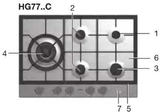
text_image
HG77..C 2 1 4 6 3 7 5
text_image
HG92..B/C 1 2 3 6 3 7 5
text_image
HG97..B/C 1 2 4 6 3 2 7 5natural_image
Three black metal components with holes and mounting holes, arranged in a staggered layout (no text or symbols visible)HG77/97
natural_image
Four abstract geometric shapes arranged in a grid: rectangular, square, cube, and circular (no text or symbols)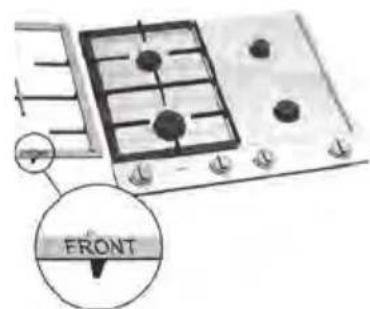
text_image
FRONTHG92
text_image
苗苗苗text_image
Technical diagram of a mechanical assembly with numbered parts for identificationWokbrander
text_image
Technical diagram of a mechanical assembly with numbered parts labeled 1 to 4Sudder-, normaal- en sterkbrander
- Branderkop
- Branderkelk
- Bougie
- Thermokoppel
natural_image
Close-up of mechanical components including a cylindrical housing and a central knob (no visible text or symbols)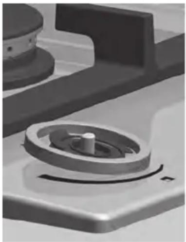
natural_image
Close-up of a mechanical component with a central circular feature and a curved base (no visible text or symbols)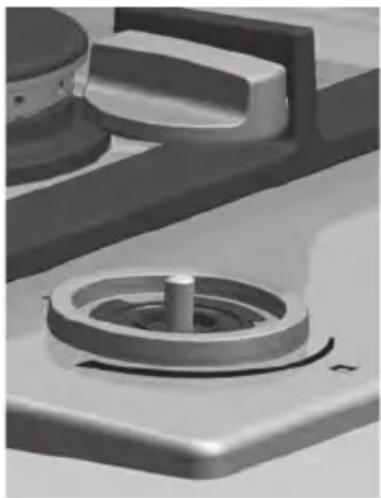
natural_image
Close-up of a mechanical component with a central shaft and circular housing (no visible text or symbols)Keradur® branderkelken
natural_image
Technical line drawing of a mechanical component with a circular feature and base plate (no text or symbols)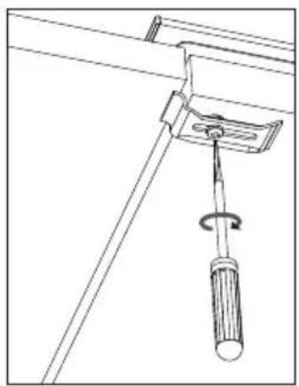
natural_image
Technical line drawing of a mechanical clamp or bracket assembly with a screwdriver (no text or symbols)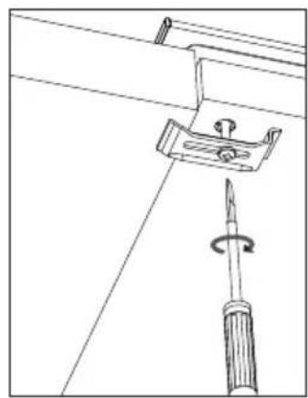
natural_image
Technical line drawing of a screwdriver inserted into a bracket with a rotating screw (no text or symbols)natural_image
Isometric line drawing of a rectangular frame with two inner rectangular cutouts (no text or symbols)Inbouwmaten HG62..B/C
natural_image
Symbol of a trash bin with crossed lines indicating no waste or discharge (no text or numbers present)Declaration of conformity
We declare that our products meet the applicable European Directives, Decisions and Regulations and the requirements listed in the standards referenced.
Technische gegevens
Safety instructions 6
Controls
Igniting and adjusting 9
Comfortable cooking
Optimal use of the hob 12
Maintenance
General 14
Status codes
Table 19
Troubleshooting
Faults table 20
Installation instructions
General 22
Building in 24
Gas information 32
Appendix
Disposal of appliance and packaging 33
Technical data 33
Introduction
This gas hob has been designed for the true cooking enthusiast. The differences in burner capacity allow you to cook any type of dish. The control buttons have an integrated spark ignition, which means that you need only one hand to ignite and operate the burners. With the HG77 and HG97 models, at least 2 burners remain available for cooking other dishes while cooking food in the wok, thanks to the spacious layout of the wok burners.
KOOKKEUR ^^
This appliance complies with all requirements set by the Cooking Approval quality mark. The gas hob combines high efficiency with a minimum of incompletely burned combustion gases. This gives you an appliance with short heating times, while also providing excellent simmering.
Your gas hob has a flame failure device. This ensures that the gas supply is shut off if the flame goes out during cooking.
First read the user instructions carefully and completely before starting to use the appliance, and keep them carefully for future reference.
Stick the data card in the space provided, at the back of the manual.
Description
- Simmer burner
- Semi-rapid burner
- Rapid burner
- Wok burner
- Pan support
- Drip tray
- On/Off button
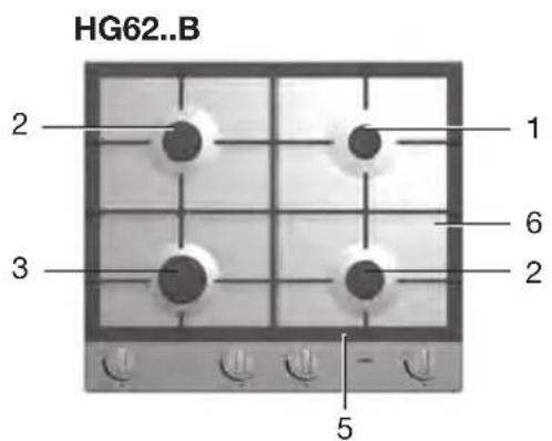
text_image
HG62..B 2 1 3 6 2 5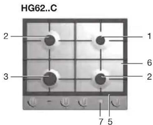
text_image
HG62..C 2 1 3 6 2 7 5
text_image
HG77..B 2 1 4 6 3 5
text_image
HG77..C 2 1 4 6 3 7 5
text_image
HG92..B/C 1 2 3 6 3 7 5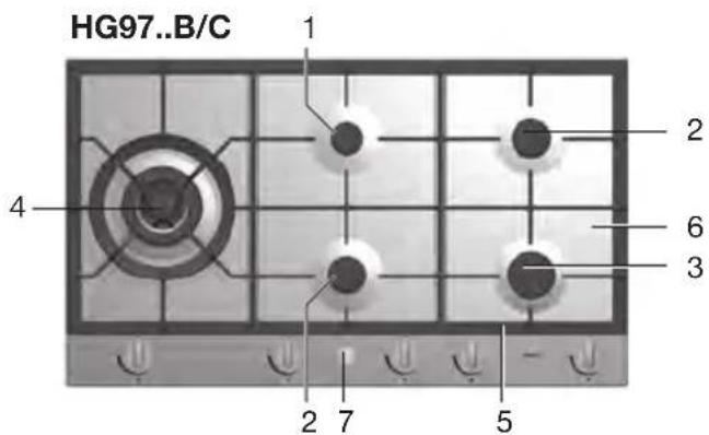
text_image
HG97..B/C 1 2 4 6 3 2 7 5Safety instructions
What you should pay attention to
- Ensure that there is adequate ventilation during use. Keep natural ventilation openings open. When using the hob for long periods, extra ventilation is necessary. Open a window for instance or install a mechanical fan.
- Use the hob only for preparing dishes. The appliance is not suitable for space heating.
- Never flambé under an extractor hood. The high flames can cause a fire, even if the fan is switched off.
- The burner parts are hot during and immediately after use. Do not touch them, and avoid contact with non-heat-resistant materials. Never immerse hot burner parts in cold water. The rapid cooling can damage the enamel.
- The distance from the pan to a knob or non-heat-resistant wall should always be greater than two centimetres. In case of smaller distances the high temperature may cause the knobs or wall to discolour and/or distort.
- Always use the pan supports and suitable cooking utensils. Always place the pan on the pan support. Placing the pan directly on the burner head can result in dangerous situations. Aluminium trays or foil are not suitable as cooking utensils. They can become burnt into the burners and pan supports.
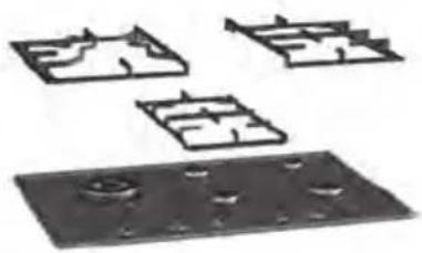
- Installing burner parts and pan supports. The hob can only function effectively if the burner parts have been assembled using the guide ridges. Ensure that the pan supports lie properly against each other and flat on the drip tray. Only then can the pans be positioned stably.
Safe use
- The device will become hot during use and will remain so for some time after it has been switched off. So please be sure not to touch the device while it is hot.
- Always wear oven gloves or use oven cloths when operating the device.
Keep oven gloves or oven cloths away from the flame.
- Do not warm closed tins and such like on the hob.
There will be a buildup of pressure that will cause tins to explode. You might get injured or scalded.
• The device is not to be positioned nor used outdoors.
- Do not use the device as a worktop.
The device may be switched on by accident or still be hot, which means objects could melt, become hot or catch fire.
- Never cover the device with a cloth or something similar.
If the device is still hot or is switched on, there is a risk of fire.
- Be extra careful when using oils or fats.
Overheated oil or fats may catch fire. Risk of fire!
Under no circumstances should you use water to try and extinguish the flames if the oil or fat were to catch fire!
Extinguish the flames with a suitable lid, a damp cloth or some such object.
- If there is a drawer underneath the device, without an intermediate bottom, this should not be used to store highly flammable objects/materials.

Children
- WARNING: The appliance and its accessible parts become hot during use. Care should be taken to avoid touching heating elements. Children less than 8 years of age shall be kept away unless continuously supervised.
- This appliance can be used by children aged from 8 years and above and persons with reduced physical, sensory or mental capabilities or lack of experience and knowledge if they have been given supervision or instruction concerning use of the appliance in a safe way and understand the hazards involved.
- The device will become hot during use and will remain hot for some time after it has been switched off.
- Do not keep objects in cupboards above or behind the device that children might find interesting.
- Children may sustain burns when they pull pots or pans off the device. A special frame that stops children from getting close to the device is available from the specialist dealer.
- If the safety instructions and warnings are not heeded, the manufacturer can not be held liable for any consequential damage.
Igniting and adjusting
Each burner can be adjusted continuously between the high and low positions.
HG....B
text_image
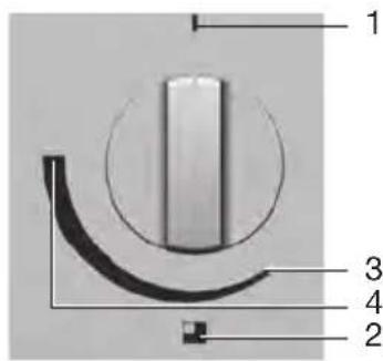
1 3 4 2- 0-setting
- Burner indication
- Low setting
- High setting
HG....C
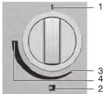
text_image
1 2 3 4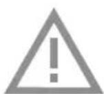
Flame failure device
Your gas hob has a flame failure device. This ensures that the gas supply is shut off if the flame goes out during cooking.
Operating the thermal flame failure device
(HG....B)
- Press the control knob and turn it anti-clockwise. Hold the control knob pressed in high setting for approximately 3 seconds after the burner has ignited.
The flame failure device switches on.
Operating the electronic flame failure device
(HG....C)
- Press the central On/Off button.
The green button is lit.
- Turn the required control knob anti-clockwise.
The burner ignites immediately. The flame failure device checks to see if there is a flame.

If all the control knobs are turned to the 0-setting, the central On/Off button automatically turns off after 3 minutes.
Extra characteristics electronic flame failure device (HG62..C/HG77..C /HG92..C/HG97..C)
Re-ignition
If the flame goes out during cooking, the device automatically attempts to restart the flame.
If no flame is detected within 10 seconds after the re-ignition attempt, the gas supply to the burner is cut off.
Emergency stop
If you need to switch off the gas hob in one go, press the central On/Off button.
Childproof lock
You can lock the gas hob to prevent accidental ignition of the burners. The gas hob can be locked and unlocked by depressing the On/Off button for 5 seconds.
You cannot switch on the childproof lock during cooking.
Cooking time limiter
If a burner has been on for an unusually long time (approximately 6 hours), it will be turned off automatically.
Status codes
The gas hob status is indicated by the light in the On/Off button. The overview on page 17 shows the codes with corresponding statuses.
Optimal use of the hob
text_image
Wrong Right- Always ensure that the flames remain below the pan so that no energy is lost and the handles don't get overheated.
- Do not use pans with a base diameter less than 12 cm.

- Use the rapid or wok burner for frying, stir-frying, heating large quantities and deep-frying.
• Use the simmer burner for preparing sauces, simmering and boiling. - Use the normal burners for all other dishes.
• Cook with the lid on the pan to save up to 50% energy.
• Use pans with a flat, clean, dry base.
Wokburner (type HG77 and HG97)
Use the wok burner to prepare dishes at very high temperatures (stir-fry).

Important:
- Cut the ingredients into strips, slices or pieces before cooking.
- Use a small quantity of good-quality oil. Butter and margarine will burn because of the high heat.
- Place the dishes with the longest cooking time in the pan first to have all ingredients cooked al dente.
natural_image
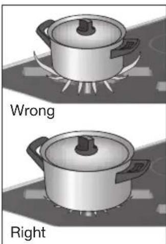
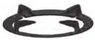
Abstract black circular shape with two petal-like cutouts, resembling a stylized cat face (no text or symbols)Use of the wok auxiliary support
The auxiliary support (supplied with the wok burner or available as accessory) provides additional stability in the case of a wok with a round base.
The auxiliary support has special recesses so it can be positioned neatly on top of the standard wok support.
General

Your appliance has been manufactured from high-grade materials, which are easy to clean.
- Regular cleaning immediately after use prevents over-cooked food being able to become ingrained and cause stubborn stains that are difficult to remove. Use a mild cleaning agent.
- Clean the control knobs, burners and pan supports first and then the stainless steel drip tray. This avoids the stainless steel drip tray getting dirty again during cleaning.
- Clean the spark plugs preferably with a cloth. Do this carefully, the spark plug can become defective. The sparkplug will only operate correctly in a dry environment. If the plug is very dirty, you may clean the point with a tiny brush.
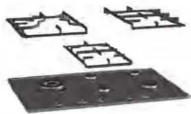
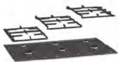
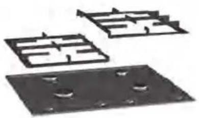
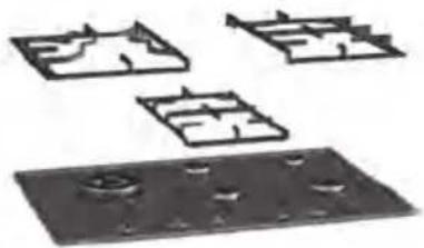
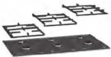
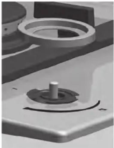
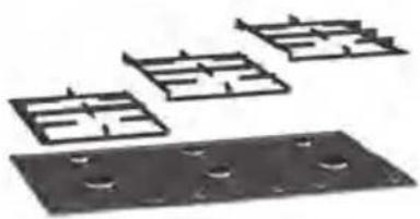
- Set the pan supports down vertically, without sliding them over the stainless steel drip tray. Place the pan supports back in the right order. The text 'FRONT' at the bottom of all pan supports helps positioning these parts (see illustrations).
HG62
natural_image
Three black metal plate components with holes, arranged in a staggered layout (no text or symbols visible)HG77/97
natural_image
Three abstract architectural floor plan diagrams with no text or symbols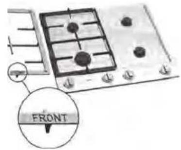
text_image
FRONTHG92
natural_image
Three black plastic components with holes, arranged in a row (no text or symbols visible)• Assemble the burner parts using the guide ridges.
text_image
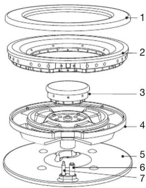
Technical diagram of a mechanical assembly with numbered parts for identificationWok burner
- Burner cap outer ring
- External torch head
- Internal lid and torch head
- Gas base
- Burner base
- Spark plug
- Thermocouple
text_image
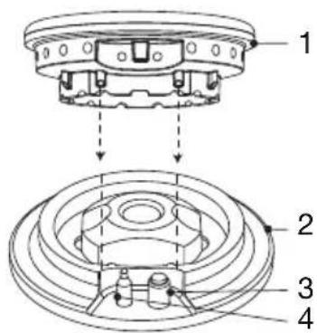
Technical diagram of a mechanical assembly with numbered parts labeled 1 to 4Simmer-, semi-rapid and rapid burner
- Burner head
- Burner base
- Spark plug
- Thermocouple
Stubborn stains on enamel (pan supports, burner caps and drip trays)
- Remove with a non-abrasive cream or a soft sponge.
- Never use scouring powder, scouring pads, sharp objects or abrasives.
Stubborn stains on stainless steel (drip trays)
- Stubborn stains on stainless steel are best removed with a cleaning agent for stainless steel. Always polish in the direction of the steel structure to avoid shine spots. (This kind of damage is not covered by the warranty!)
- If the above methods do not remove the stains, clean the plate with a special cleaning agent for stainless steel (see our website ‘www.atagservice.nl’). Remember to treat the entire drip tray in order to avoid discolouring. Also, as a follow-up treat the drip tray with a polish or maintenance agent for stainless steel.
- Please note that over the years the surface will slightly discolour.
Cleaning the pan support
- Do not clean the pan supports in the dishwasher, as the connection with the rubber feet is not suitable for that purpose. If the rubber feet are lost, the pan support may damage the drip tray.
Brass wok burner parts
- A few parts of the work burner are made from brass. The colour of the brass will change as a result of high stir-fry temperatures.
Cleaning removable burner components
- Use a mild cleaning product and a soft cloth to clean the removable burner components (including wok).
• With obstinate stains, soak the parts in hot suds. - Burner parts should not be cleaned in the dishwasher. The parts may be damaged by the dishwasher detergent!
- Never use scouring powder, scouring pads, sharp objects or abrasives.
Cleaning removable knobs and rosettes
- If the knobs and rosettes are very dirty, you can remove them temporarily to clean them. Use a mild cleaning product and a soft cloth. Wearing rubber gloves makes it easier to remove the knob!
Attention! Avoid an excess of moisture around the knob holes when cleaning.
- When you install the rosettes, remember to push them under the silicone sealing ring (see illustration). This ring has three positioning ridges which fit on the inner circle of the rosette.
natural_image
Close-up of a mechanical component with a central knob and circular features (no visible text or symbols)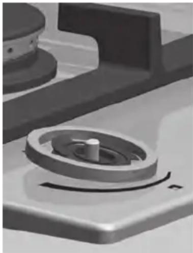
natural_image
Close-up of a mechanical component with a central knob and circular housing (no visible text or symbols)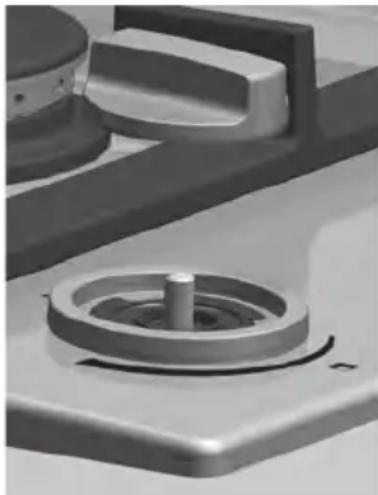
natural_image
Close-up of a mechanical component with a central shaft and circular housing (no visible text or symbols)Keradur® burner bases
- The burner bases have a unique Kerad® surface coating. The special dirt-repelling lacquer has a ceramic filling which makes cleaning easier and substantially improves the durability of the burners.
- Clean the burner bases with a mild cleaning product and a soft cloth.
Table
On/Off button
The On/Off button on the HG....C appliances can indicate a number of functions and faults.
| SYMPTOM STATUS SOLUTION | |||
| LEDs in the button aren't shining. | The appliance is switched off. - | ||
Green LED in the button is shining continuous. | The appliance is turned on. - | ||
Green LED in the button is blinking. | Child lock. | Hold the on/off button pressed in for 5 seconds, and you can use the gas hob again. | |
Green and red LED in the button are blinking after each other.  | A fault occurred by reigniting a burner. | Check the gas supply to your gas hob and/wether the burner parts are positioned in the right way.Turn every button to the 0-setting and try to ignite the burner again. | |
Red LED in the button is blinking. | Your gas hob has become too hot. | Let your gas hob cool down and you can use it again. | |
Red LED in the button is shining continuous. | A fault occurred in the electronics of your gas hob. | Contact your service centre. | |
Faults table
If the appliance does not work properly, this does not always mean that it is defective. Try to find a solution first by checking the points mentioned in the table below, or contact the service department.
(See the guarantee certificate for details.)
| FAULT CAUSE SOLUTION | ||
| Smell of gas in the vicinity of the appliance. | The gas connection of the gas hob is leaking. | Turn off the gas mains.Contact your gas fitter. |
| Burner does not ignite. Plug not in socket.Fuse defective/fuse in meter cabinet switched off.Spark plug dirty/damp.Burner parts not correctly installed.Burner parts dirty/damp.Main gas tap closed.Fault in the gas network.Gas bottle or tank is empty.Wrong type of gas used (if bottled gas is used). | Push the plug into the socket.Fit a new fuse or switch the automatic fuse back on.Clean and dry the spark plug.Assemble the burner parts using the centring ridges.Clean and dry the burner parts, making sure that the outflow holes are open.Open the main gas tap.Check with your gas supplier.Connect a new gas bottle or have the tank filled.Check that the gas used is suitable for the appliance. | |
| A burner does not ignite. Control knob not kept pressed in far enough.(Only for B versions. For electronically protected appliances, see the On/Off button table). | Keep the control knob pressed in far enough between high and low. At first use, this can take some more time because of the gas supply. | |
| Burner does not burn evenly. Burner parts incorrectly installed.Burner parts dirty or damp.Wrong type of gas used (if bottled gas is used). | Assemble the burner parts using the centring ridges.Clean and dry the burner parts, making sure that the outflow holes are open.Check that the gas used is suitable for the appliance. | |
| Burner goes out after igniting. Control knob not kept pressed in long enough.(Only for B versions. For electronically protected appliances, see the On/Off button table). | Keep the control knob pressed in for at least 5 seconds. | |
General
Caution!
- The fitting of the appliance should only be carried out by a certified installer.
- The type of gas and the country for which the appliance has been designed are indicated on the data card.
• This is a category 3 appliance.
Gas connection
- The gas connection must comply with national and local regulations.
- We recommend that the hob be connected by means of a fixed pipe.
- Connection using a specially designed safety hose is also permitted.
• Behind an oven always install a full metal pipe.
Warning!
- A safety hose may not be bent and must not come into contact with moving parts of kitchen units.
- In all cases the connection tap for the appliance must be positioned at an is easily accessible location.
- Before using the appliance for the first time, verify that there are no gas leaks using water and washing-up liquid at the gas connections.
Electrical connection
230V - 50Hz - 1.1 VA (for ..B appliances)
230V - 50Hz - 5.1 VA (for ..C appliances)
- The electrical connection must comply with national and local regulations.
- Wall socket and plug must be accessible at all times.
- If you make a permanent connection, ensure that an omnipolar switch with a contact gap of at least 3 mm is fitted in the supply cable.
- Do not use an adapter or an extension lead to connect the device to the electrical mains. Safe use of the device cannot be guaranteed with these accessories.

Warning!
• This appliance must be earthed.
- Damaged connection cables must be replaced by the manufacturer's service department (or by a person with equivalent qualifications).
The device should be disconnected from the mains prior to installation, maintenance or repairs. The device is only disconnected from the electric power if:
- the main switch of the electrical wiring/installation in the house is switched off, or
- the fuse for the electrical wiring/installation in the house has been completely removed, or
- the plug has been pulled out of the socket.
Faulty parts may only be replaced by original Atag parts. Only those parts are guaranteed by Atag to meet the safety requirements.
Building in
Preparing the hob
- Fit the elbow supplied on the appliance's gas connection.
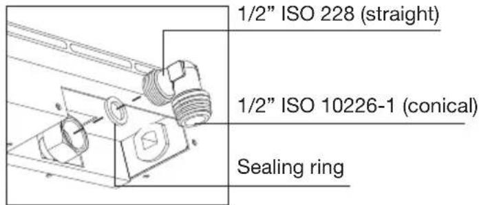
text_image
1/2" ISO 228 (straight) 1/2" ISO 10226-1 (conical) Sealing ringOnly for France:
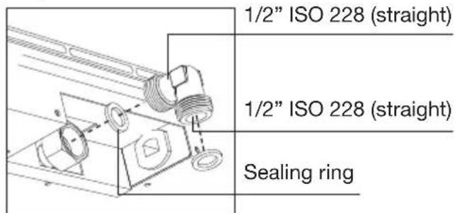
text_image
1/2" ISO 228 (straight) 1/2" ISO 228 (straight) Sealing ringCut opening in worktop
- Cut the opening in the worktop very accurately (see building in dimensions).
- If the worktop is made of treated wood, coat the sawn surfaces of the top with sealing varnish, to prevent moisture causing the top to swell.
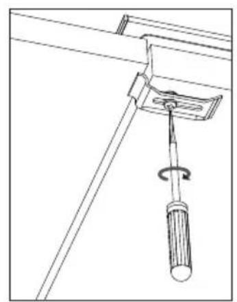
Attachment points for mounting brackets
See 1* in the illustrations of dimensions for Building in from page 24 onwards for the attachment points for mounting brackets.
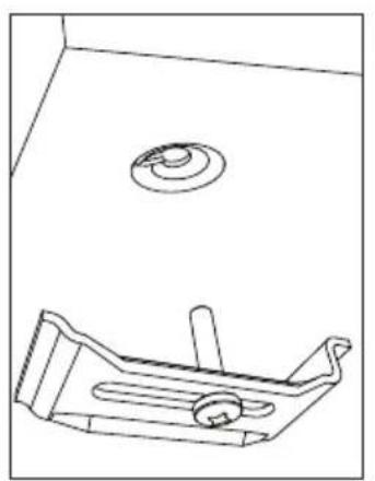
natural_image
Technical line drawing of a mechanical component with a circular top and base plate (no text or symbols)Screw hole for mounting bracket Thin worktops Thick worktops
natural_image
Technical line drawing of a mechanical clamp or bracket assembly (no text or symbols)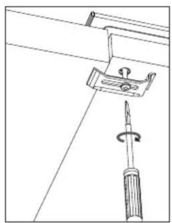
natural_image
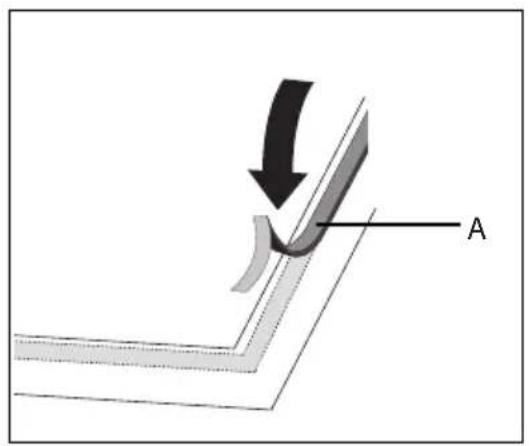
Technical line drawing of a screwdriver inserted into a bracket with a handle (no text or symbols)Placing the sealing tape
- Remove the protective foil from the sealing tape (A) and apply the tape around the cut-out in the worktop.
text_image
A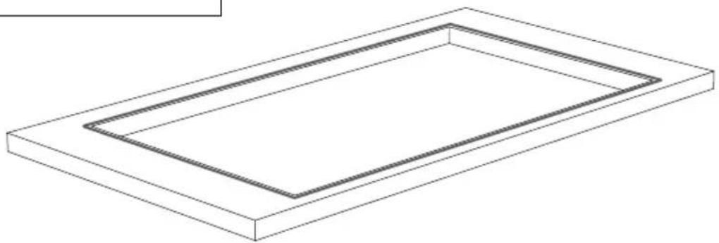
natural_image
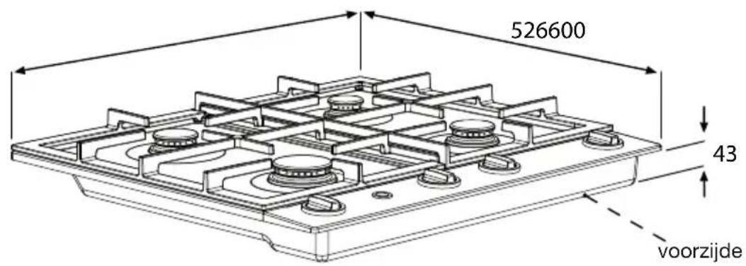
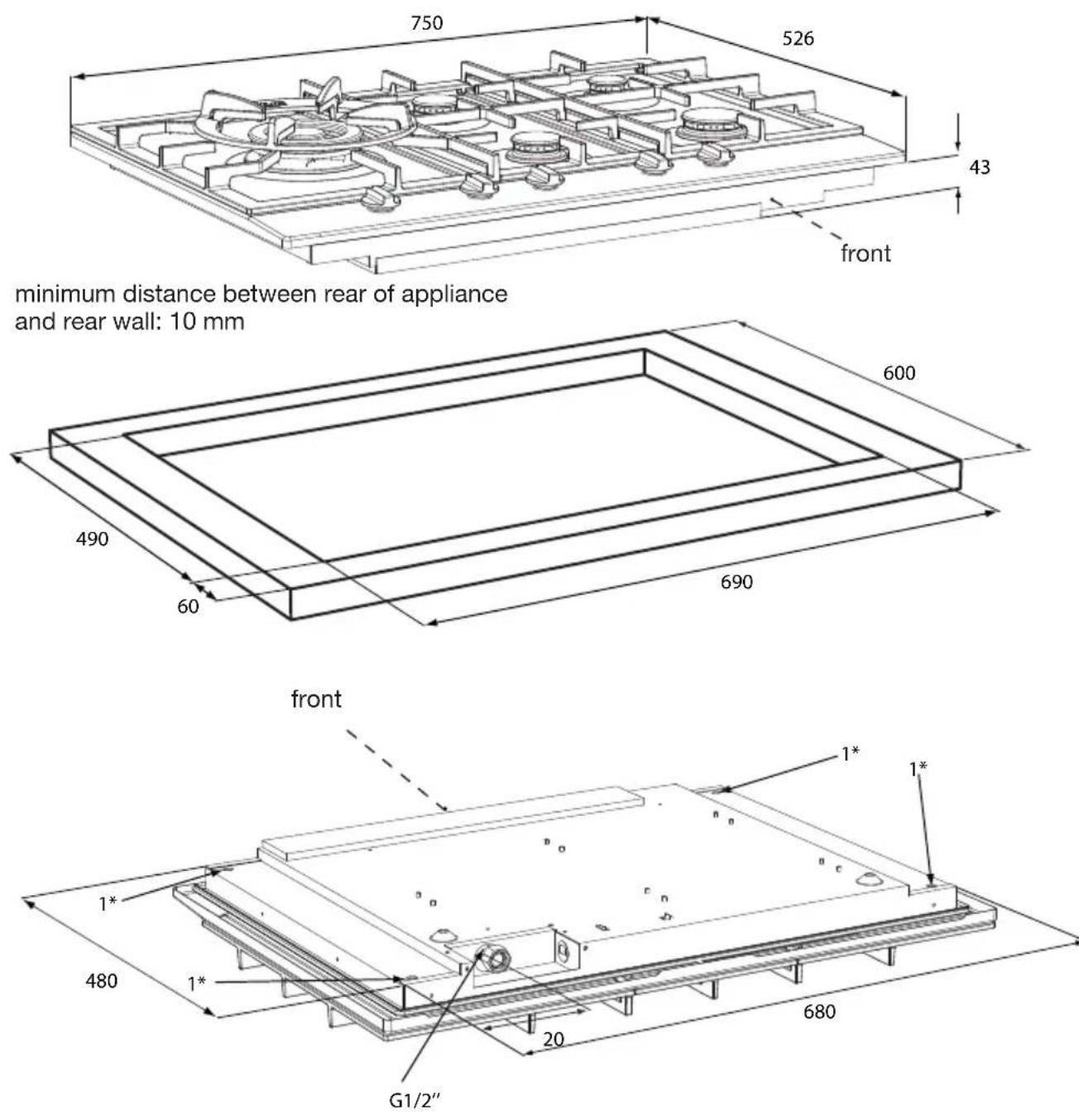
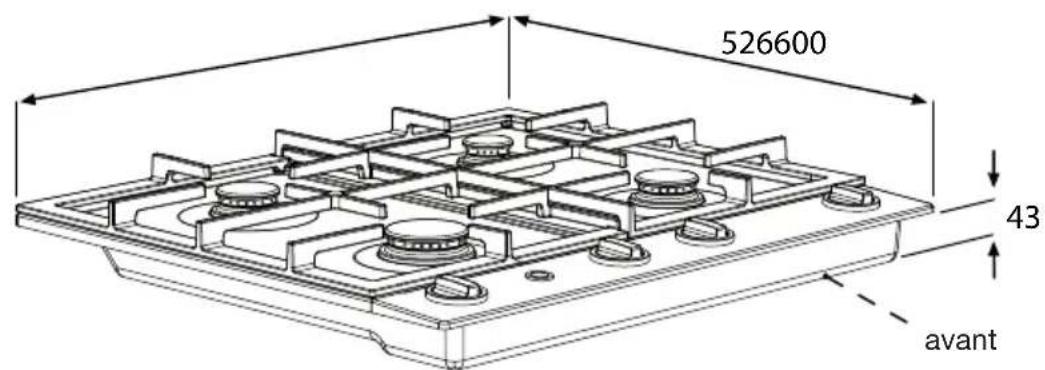
Isometric line drawing of a rectangular frame with two inner rectangular cutouts (no text or symbols)Building in dimensions HG62..B/C
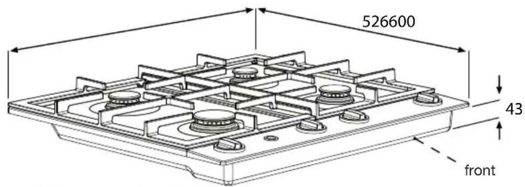
text_image
526600 43 frontminimum distance between rear of appliance and rear wall: 10 mm
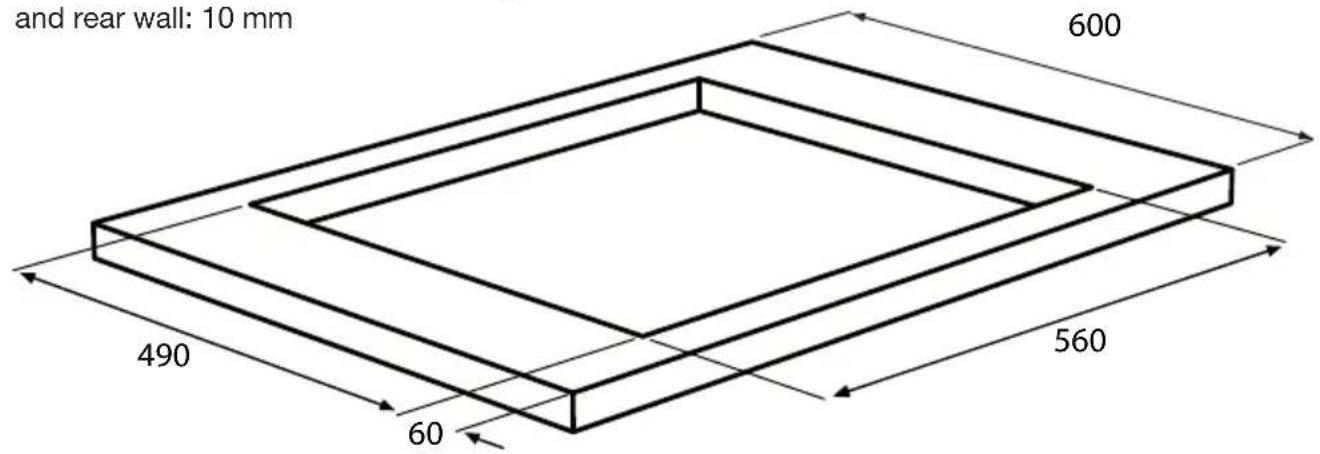
text_image
and rear wall: 10 mm 600 490 60 560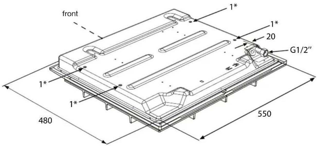
text_image
front 1* 1* 20 G1/2" 1* 1* 480 550Building in dimensions HG7711B/C
minimum distance between rear of appliance and rear wall: 10 mm
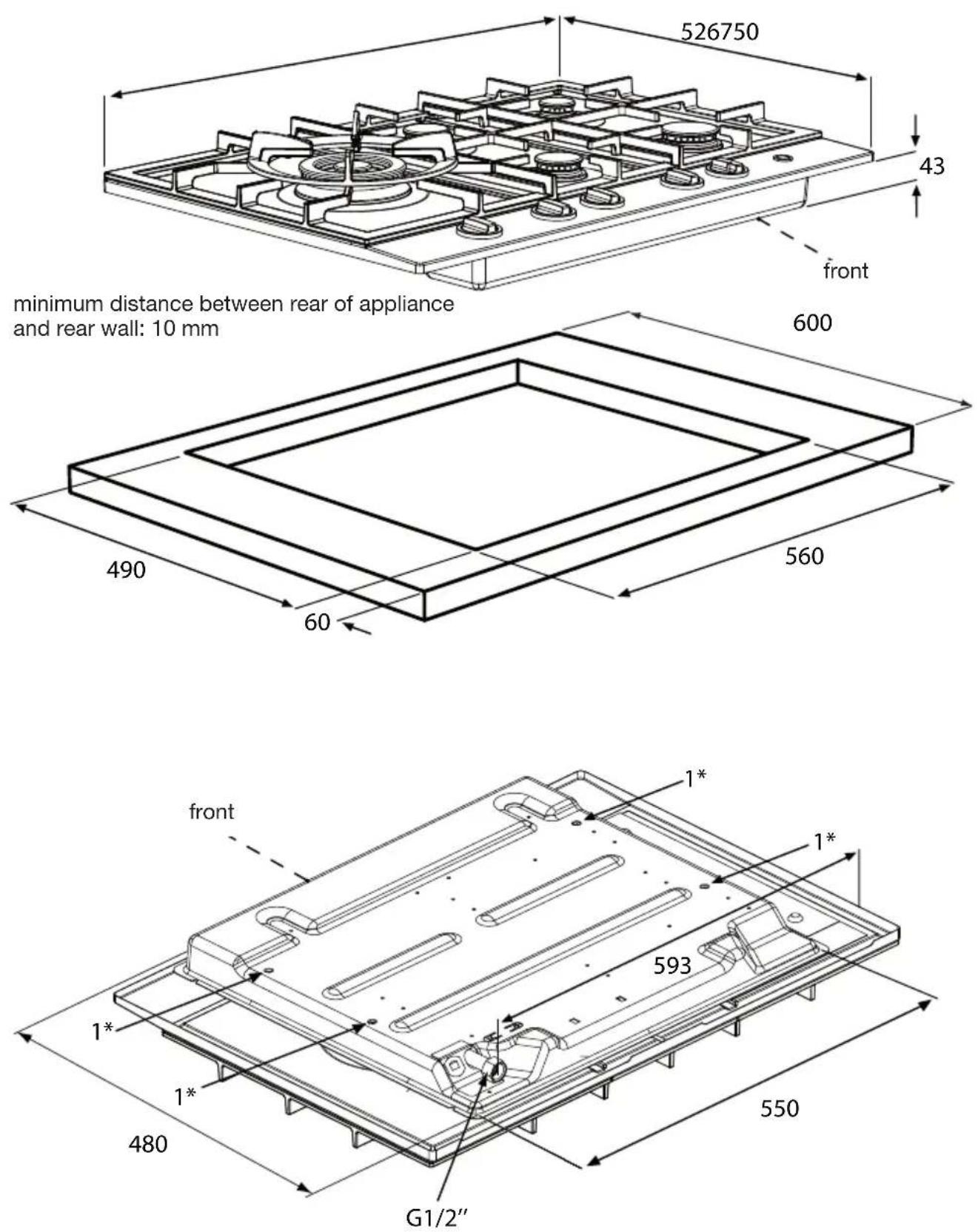
Building in dimensions HG7792B/C
minimum distance between rear of appliance and rear wall: 10 mm
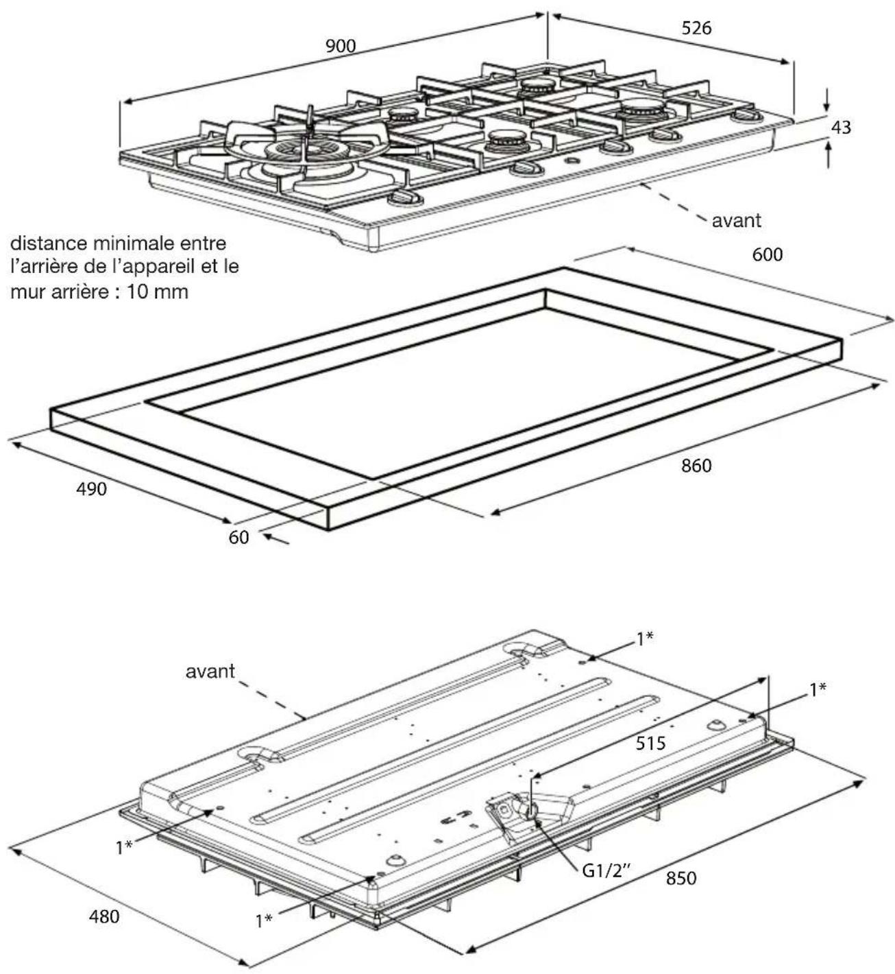
Building in dimensions HG92..B/C

text_image
minimum distance between rear of appliance and rear wall: 10 mm 900 526 43 front 600 490 860 60 front 1* 515 G1/2" 850 480 1* 1*Building in dimensions HG97..B/C
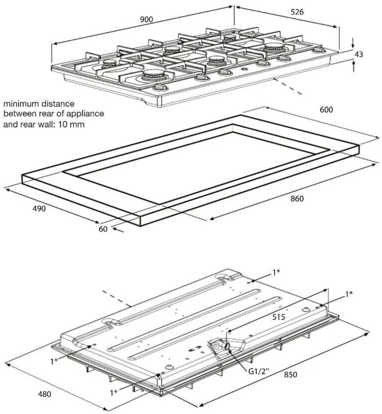
minimum distance
between rear of appliance
and rear wall: 10 mm
Space to be left free around the appliance
A hob generates heat. Leave sufficient distance between the appliance and any non heat-resistant materials. Be cautious with materials that may discolour (such as stainless steel).
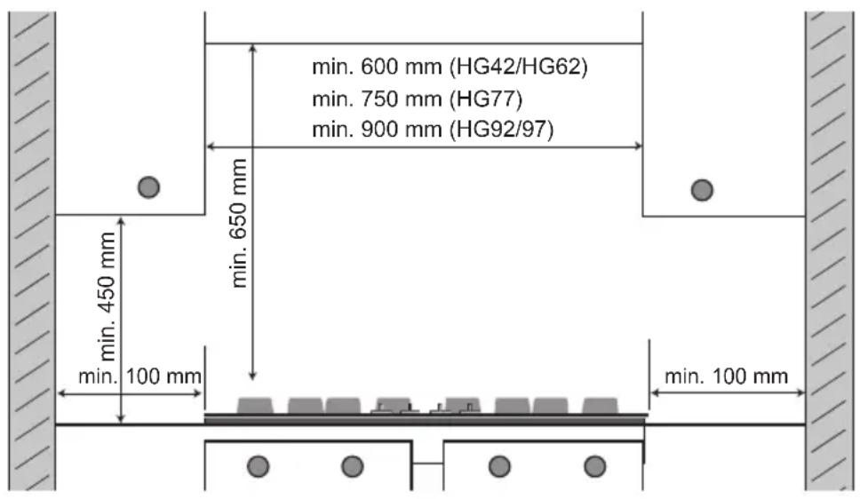
- The bottom of the hob becomes hot. Do not place combustible items in a drawer if the drawer is fitted directly below the hob.
Install appliance and make connections
- Place the appliance in the worktop and secure it using the mounting brackets and screws supplied.
- Connect to the gas supply.
- Verify that there are no gas leaks using water and washing-up liquid at the gas connections.
- Connect the appliance to electricity mains.
Gas information
| G25/25 mbar | G20/20 mbar | G25/20 mbar | G30/29 mbar | G31/29 mbar | G31/36 mbar | G30/50 mbar | G31/50 mbar | G31/67 mbar | |
| Burner-type | (kW) (kW) | (kW) (kW) | (kW / g/h) | (g/h) | (kW / g/h) | (kW / g/h) | (kW / g/h) | (kW / g/h) | (kW / g/h) |
| Simmer | 1.00 1.00 | 0.90 0.90 / | 65 0.79 / 57 | 0.90 / 65 | 1.00 / 72 | 0.88 / 63 | 1.00 / 72 | ||
| Semi-rapid | 2.00 2.00 | 1.80 1.60 / | 115 | 1.41 / 101 | 1.60 / 115 | 2.00 / 144 | 1.76 / 127 | 2.00 / 144 | |
| Rapid 3.00 | 3.00 2.70 | 2.30 / | 166 | 2.02 / 146 | 2.30 / 166 | 2.70 / 194 | 2.38 / 171 | 2.70 / 194 | |
| Wok 4.50 | 4.50 4.50 | 3.50 / | 252 | 3.08 / 222 | 3.50 / 252 | 4.00 / 288 | 3.52 / 253 | 4.00 / 288 |
Setting up the appliance for other gas
This appliance has been set up for natural gas (G25/25 or G20/20). The appliance can be set up for other gas types and pressures by means of a conversion kit. You can order the kit from the sales and service organisation. The conversion instructions are supplied with the kit.
Disposal of appliance and packaging
The packaging of this appliance is recyclable and may have been made of:
- cardboard
paper - polythene foil (PE)
• CFC-free polystyrene (PS hard foam)
• polypropylene tape (PP).
Dispose of these materials in a responsible manner and in accordance with government regulations.
natural_image
Symbol of a trash bin with crossed x- and y-axes, no text or numbers presentThe appliance carries the symbol of a crossed-out dustbin to state that segregated processing is compulsory to avoid any negative effects on the environment and public health. This means that at the end of its working life, you must hand it in at a special refuse collection centre run by your local authority or dealer.
Segregated processing enables the recovery of the materials used in the production of this appliance, thus saving considerably in terms of raw materials and energy.
CE
Declaration of conformity
We declare that our products meet the applicable European Directives, Decisions and Regulations and the requirements listed in the standards referenced.
Technical data
On the label on the bottom of this equipment, you will find the total wattage, the required voltage and the frequency.
text_image
HG62..B 2 1 3 6 2 5
text_image
HG62..C 2 1 3 6 2 7 5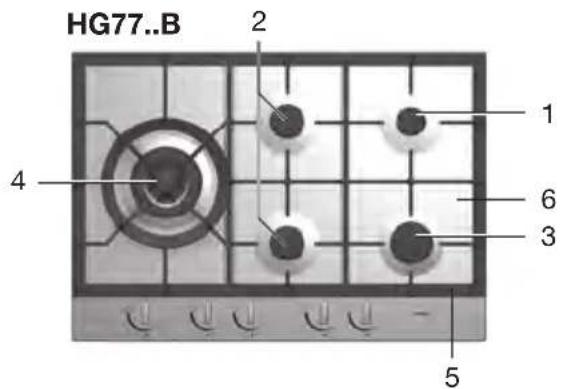
text_image
HG77..B 2 1 4 6 3 5
text_image
HG77..C 2 1 4 6 3 7 5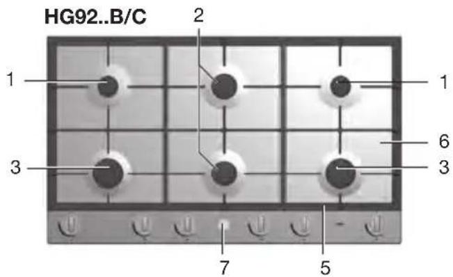
text_image
HG92..B/C 1 2 3 6 3 7 5
text_image
HG97..B/C 1 2 4 6 3 2 7 5Sécurité
text_image
Faux Correctnatural_image
Abstract black circular shape with two petal-like cutouts, resembling a stylized cat face (no text or symbols)natural_image
Three black metal plate components with holes, arranged in a grid pattern (no text or symbols visible)HG77/97
natural_image
Three technical diagrams showing different layout arrangements of rectangular components on a dark surface (no text or symbols present)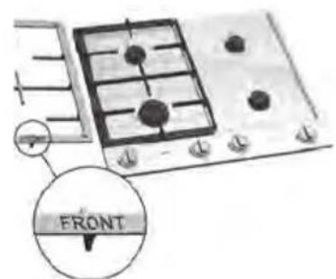
text_image
FRONTHG92
natural_image
Three black metal plates with circular indentations, arranged in a row (no text or symbols visible)text_image
Technical diagram of a mechanical assembly with numbered parts for identificationBrûleur Wok
text_image
Technical diagram of a mechanical assembly with numbered parts labeled 1 to 4natural_image
Close-up of a mechanical component with a central bolt and circular housing (no visible text or symbols)
natural_image
Close-up of a mechanical component with a central knob and circular housing (no visible text or symbols)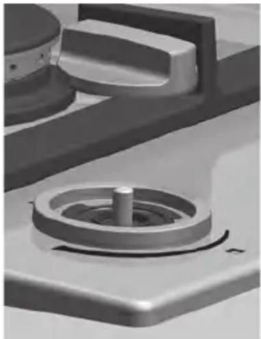
natural_image
Close-up of a mechanical component with a central shaft and circular housing (no visible text or symbols)natural_image
Technical line drawing of a mechanical component with a circular top and base plate (no text or symbols)
natural_image
Technical line drawing of a mechanical clamp or bracket assembly (no text or symbols)
natural_image
Technical line drawing of a screwdriver inserted into a bracket with a tool, no text or symbols presentnatural_image
Isometric line drawing of a rectangular frame with two inner rectangular outlines (no text or symbols)Dimensions hors HG62..B/C
text_image
526600 43 avantDimensions hors HG92..B/C
natural_image
Symbol of a trash bin with crossed x-marks and a blank rectangular base (no text or numbers)Declaration of conformity
We declare that our products meet the applicable European Directives, Decisions and Regulations and the requirements listed in the standards referenced.