
YT-828296 - Sander Yato - Free user manual and instructions
Find the device manual for free YT-828296 Yato in PDF.

User questions about YT-828296 Yato
0 question about this device. Answer the ones you know or ask your own.
Ask a new question about this device
Download the instructions for your Sander in PDF format for free! Find your manual YT-828296 - Yato and take your electronic device back in hand. On this page are published all the documents necessary for the use of your device. YT-828296 by Yato.
USER MANUAL YT-828296 Yato
LT AKUMULIATORINIS ŠLIFUOKLIS RINKINYS
LV AKUMULATORA SLIPMAŠINA KOMPLEKTS
CZ SADA AKUMULÁTOROVÝCH BRUSEK
SK SÚPRAVA AKUMULÁTOROVÝCH BRÚSOK
HU AKKUMULÁTOROS CSISZOLÓGÉP KÉSZLET
RO SET POLIZOARE CU ACUMULATOR
NL EEN SET DRAADLOZE SCHUURMACHINES
natural_image
Pure technical diagram showing two circular components with cross-sectional views and directional arrows, no text or symbols present.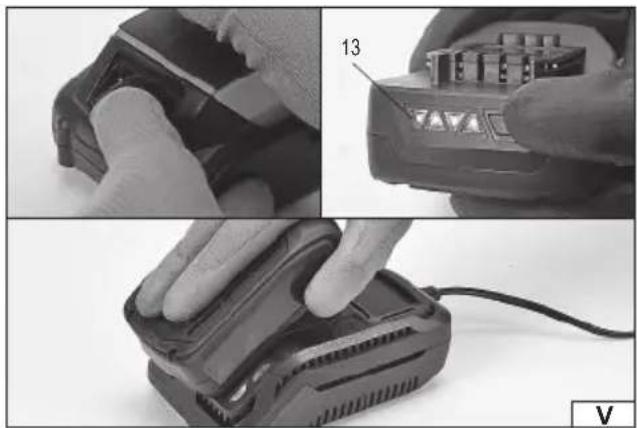
natural_image
Three-panel black-and-white photo showing hands using a battery pack and a charging device, with no visible text or symbols.
natural_image
Close-up of a hand holding a handheld device with a control panel (no visible text or symbols)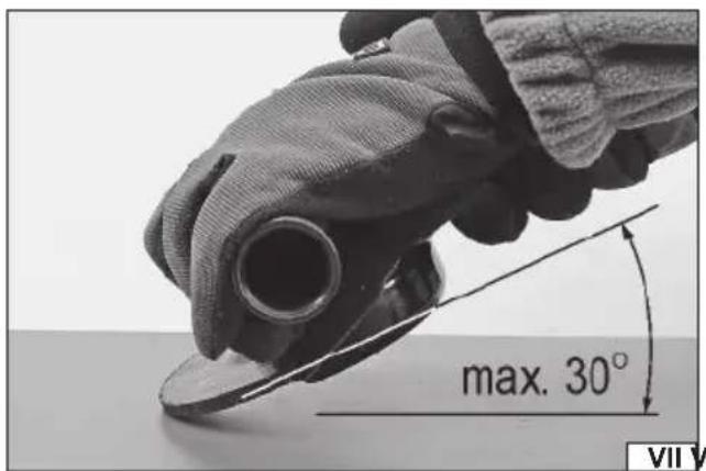
natural_image
Close-up of hands using a power tool to cut a circular component with directional arrows indicating rotation (no text or symbols visible)- body
- additional handle
- abrasive disk guard
- spindle
- spindle lock
- switch
- speed regulation
- abrasive disk (grinding wheel)
- lower mounting fl ange
- upper mounting fl ange
- rechargeable battery
- battery charger
- battery charge indicator
- battery latch
LT
natural_image
Close-up of gloved hands using a mechanical tool to handle a small metallic component (no text or symbols visible)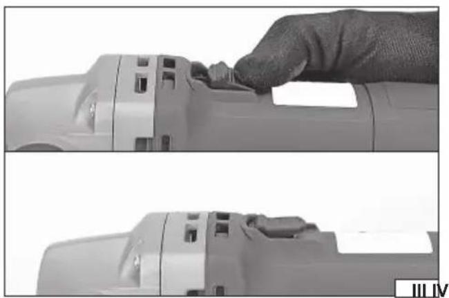
natural_image
Two-panel black-and-white photo showing a hand pressing down on a device component, no visible text or symbols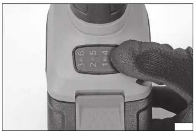
natural_image
Close-up of a hand pressing down on a white handheld device with a rotary dial (no visible text or symbols)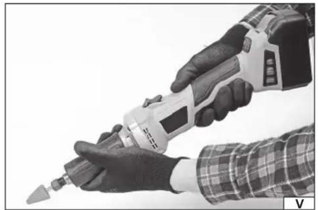
natural_image
Close-up of hands using a power tool, no visible text or symbols- body
- electric power switch
- speed control
- fi xing nut
- tool chuck
- battery socket
- wrench
DE
Read the operating instruction
Wear protective goggles
Wear hearing protectors
Always work the grinder holding it with two hands
Do not use for cutting
This symbol indicates that waste electrical and electronic equipment (including batteries and storage cells) cannot be disposed of with other types of waste. Waste equipment should be collected and handed over separately to a collection point for recycling and recovery, in order to reduce the amount of waste and the use of natural resources. Uncontrolled release of hazardous components contained in electrical and electronic equipment may pose a risk to human health and have adverse effects for the environment. The household plays an important role in contributing to reuse and recovery, including recycling of waste equipment. For more information about the appropriate recycling methods, contact your local authority or retailer.
The angle grinder is a power tool designed for grinding and cutting metals and mineral building materials such as brick, natural and artificial stone, concrete, glazing, etc. using abrasive discs and grinding wheels selected for a given material. Under no circumstances must the tool be used for processing materials other than those mentioned above, e.g. for grinding and cutting wood or polishing. The correct, reliable and safe operation of the grinder requires its proper use, so before using the grinder:
Read the entire instructions manual before the first use of the tool and keep it for future reference.
Always use an eye guard!
Do not use grinding discs with a maximum permissible perimeter speed of less than 80 m/s!
Do not use grinding wheels with a maximum permissible rotational speed lower than the grinder's speed.
Caution! Produced during the sanding of certain surfaces, the resulting dust can be harmful to health or toxic.
The supplier is not liable for any damage resulting from failure to observe the safety instructions and recommendations contained in this manual.
EQUIPMENT
The tool is delivered complete but requires preparation before starting work. The product is supplied with a battery pack, a charging station (charger), an abrasive disc guard, a wrench for fixing the grinding disc and an additional handle.
TECHNICAL DATA
| Parameter Unit Value | ||
| Part no. YT-828293 | ||
| Mains voltage [V] 18 DC | ||
| Rated rpm [min] | ^-1 3000 – 8500 | |
| Diameter of the abrasive disc [mm] 125 | ||
| Diameter of the abrasive disc hole [mm] 22.2 | ||
| Spindle taper | M14 | |
| Weight | [kg] | 1.26 |
| Noise level | ||
| - sound pressure L_pA ± K_pA | [dB (A)] | 89.0 ± 3.0 |
| - power L_wA ± K_wA | [dB (A)] | 97.0 ± 3.0 |
| Vibration level _a,b,AG ± K (main/additional handle) | [m/s2] | 7.28 ± 1.5 |
| Insulation class | III | |
| Protection rating | IPX0 | |
| Battery type | Li-Ion | |
| Battery capacity | [Ah] | 4 |
| Charger* | ||
| Input voltage | [V] | 220 – 240 |
| Mains frequency | [Hz] | 50/60 |
| Output voltage | [V] 21 DC | |
| Output current | [A] | 2.4 |
| Rated power | [W] | 60 |
| Charging time** | [h] | 2 |
| Parameter Unit Value | ||
| Catalogue No. | YT-82824 | |
| Rated voltage | [V] 18 DC | |
| Tool chuck diameter | [mm] | 6 |
| Max.diameter of accessories [mm] | 25 | |
| Thread size of the fixing nut | M15 | |
| Rated rpm | [min ^-1 ] | 8,000 – 26000 |
| Noise level | ||
| - sound pressure | [dB(A)] | 78.0 ± 3.0 |
| - power | [dB(A)] | 89.0 ± 3.0 |
| Vibration level | [m/s ^2 ] | 2.47 ± 1.5 |
| Protection rating | IPX0 | |
| Weight | [kg] | 1.37 |
| Battery type | Li-Ion |
EN
* only for models equipped with a battery and charger
** the specified charging time applies only to the battery with the capacity listed in the table
The declared noise emission value has been measured using the standard test method and can be used to compare one tool to another. The declared noise emission value can be used in the preliminary exposure assessment.
The declared total vibration value has been measured using the standard test method and can be used to compare one tool to another. The declared total vibration value can be used in the initial exposure assessment.
Caution! The vibration emission during tool operation may differ from the declared value, depending on the manner the tool is used.
Caution! Safety measures to protect the operator, which are based on an assessment of exposure under actual conditions of use (including all parts of the work cycle, such as the time when the tool is switched off or idle and the activation time), must be specified.
GENERAL SAFETY CONDITIONS
NOTE! Get acquainted with all the instructions below. Failure to observe them may lead to an electric shock, fire or injuries. The notion of electric tool used in the instructions applies to all the tools which are powered with electric current, both wire tools and wireless ones.
OBSERVE THE FOLLOWING INSTRUCTIONS
Place of work
The place of work must be properly illuminated and clean. Disorder and poor illumination may be a cause of accidents.
Do not work with electric tools in explosive environments, or those which contain inflammable liquids, gases or vapours.
Electric tools generate sparks, which may cause a fire in case of contact with inflammable gases or vapours.
Do not allow children and outsiders to the place of work. A lack of concentration may result in a loss of control over the tool.
Electric safety
The plug of the power supply cable must fit the mains socket. Do not modify the plug. Do not use any adapters whatsoever in order to adapt the plug to the socket. Unmodified plug which fits the socket reduces the risk of an electric shock.
Avoid contact with grounded surfaces, such as pipes, heaters and refrigerators. Grounding of the body increases the risk of an electric shock.
Do not expose electric tools to precipitation or humidity. Water and humidity which gets into the electric tool increases the risk of an electric shock.
Do not overload the power supply cable. Do not use the power supply cable in order to carry the tool or to connect and disconnect the plug from the mains socket. Avoid contact of the power supply cable with heat, oils, sharp tools and moving elements. Damage to the power supply cable increases the risk of an electric shock.
In case work is realised outside closed areas, it is necessary to use extension cords designed for applications outside closed areas. Using a correct extension cord permits to reduce the risk of an electric shock.
If operating a power tool in a damp location is unavoidable, use a residual current device (RDC) protected supply. Use of an RCD reduces the risk of electric shock.
Personal safety
Commence work in good physical and psychological conditions. Pay attention to what you do. Do not work if you are tired or under effects of medicines or alcohol. Even a moment's inattention during work may lead to serious injuries.
Always use individual means of protection. Always wear goggles. Using individual means of protection, such as dust-masks, protective shoes, helmets and hearing protections permits to reduce the risk of serious injuries.
Avoid accidental activation of the tool. Make sure the switch is in the OFF position, before you connect the tool to the mains. Holding the tool with a finger on the switch or connecting an electric tool when the switch is in the ON position may lead to serious injuries.
Before you turn an electric tool on remove all the spanners and other tools, which have been used for adjustments. A spanner left on rotating elements of the tool may lead to serious injuries.
Keep your balance. Maintain an appropriate position. It will permit to control the electric tool in case of unpredicted situations during its operation.
Use protective clothes. Do not wear loose clothes or jewellery. Keep your hair, clothes and gloves away from moving elements of the electric tool. Loose clothes, jewellery or long hair may get caught on moving elements of the tool.
Use dust extractors or dust containers, if the tool is equipped with any. Make sure they are properly connected. Using of dust extractors permits to reduce the risk of serious injuries.
Safety precautions while using the electric tool
Before the battery is installed, make sure the switch is off. Installation of the battery when the switch is on may lead to accidents.
Use solely the charger recommended by the manufacturer. Using a charger designed for another type of battery may be a cause of fi re.
EN
The electric tool must be operated exclusively with the battery indicated by the manufacturer. Using another battery may be a cause of fire or injuries.
When the battery is not used, it must be stored away from such metal objects as paper clips, coins, nails, screws or other small metal elements, which might short-circuit the terminals. Short-circuited terminals of the battery may cause burns or fire.
Under adverse circumstances liquid may leak from the battery; avoid any contact. In case of accidental contact with the liquid, rinse it with water. In case of eye contact, seek medical. The liquid leaking from the battery may cause irritation or burns.
During work when the tool may touch a hidden live conductor, the electric tool must be held by insulated handles. The installed bit in case of contact with a live conductor may conduct electricity to the metal elements of the tool, which may cause electric shock to the operator.
Repairs
The tool may be repaired only by authorised service centres, which must use solely original spare parts. It will guarantee a proper level of safety of operation of the electric tool.
ADDITIONAL SAFETY GUIDELINES FOR DISC GRINDERS AND POLISHING MACHINES
The tool is intended only for grinding, grinding with sandpaper, grinding with wire brushes and cutting. Read and view all warnings, instructions, figures, and specifications supplied with the power tool. Failure to follow all of the instructions provided below may result in electrocution, fire, or serious injury.
Do not convert this tool to make it fit for a job for which it has not been designed and specified by the manufacturer. Such conversion will result in loss of control and cause serious injuries.
It is prohibited to use the tool as a polishing machine or in any other manner which is non-compliant with the manual. Performing other works for which the tool is not intended may pose a risk and result in injuries.
Do not use accessories that have not been designed or intended for the work with the tool by the manufacturer. The fact that the accessories can be installed on the tool does not ensure safe operation.
The maximum rotational speed of the accessories must be equal to or greater than the maximum rotational speed of the tool. Accessories with a lower rotational speed than the tool speed can disintegrate into fragments during operation.
The outer diameter and thickness of accessories must be within the size range specified for the tool. It is not possible to properly guard or operate improperly sized accessories.
The size of the hole used for fixing wheels, discs, flanges, and other accessories must match the size of the tool spindle. Accessories with a fixing hole size not suitable for the tool spindle size will start to vibrate during operation, which may result in the loss of control of the tool.
Do not use damaged accessories. Before each use, examine the condition of the accessories for possible splinters, cracks, abrasions and excessive wear. If any accessories are dropped, check them for damages or install new and undamaged accessories. After checking and installing the accessories, make sure you and all bystanders stand outside the rotation plane of the accessories, then run the tool for one minute at a maximum rotational speed. Damaged accessories will disintegrate during the test.
Wear personal protective equipment. Use face shields, goggles, or safety goggles, depending on the application. If required, use dust masks, hearing protection, safety gloves, and aprons to protect against small pieces of accessories or materials generated during work. The eye protection must allow for stopping any flying debris generated during work. The dust mask must be capable of filtering out dust generated during work. Exposure to noise for too long can result in hearing loss.
Ensure all bystanders keep a safe distance from the work area. Persons entering the work area must wear personal protective equipment. Debris or pieces of damaged accessories which are generated during work can be thrown out of the immediate vicinity of the work area.
When carrying out work during which the disc may come into contact with a live concealed electrical cable or power cord, hold the sander by the insulated handles only. When the disc is in contact with a live wire, it may cause the metal parts of the tool to become live, which may lead to electrocution of the tool operator.
Keep the power cord away from rotating tool parts. If you lose control of the tool, the cord can be cut or caught, and your hand or arm can be drawn into the rotating parts of the machine.
Never put down the tool until the rotating parts have come to a complete standstill. The rotating parts can “catch” the ground and pull the tool out of your control.
Do not turn on the tool while carrying it around. Inadvertent contact with rotating parts can cause your clothes to be caught and pulled in by the tool, which can result in contact with the operator's body.
Clean the tool's ventilation openings regularly. The motor fan draws dust generated during operation inside the tool. Excessive accumulation of metal particles contained in the dust increases the risk of electrocution.
Do not use the tool near flammable materials. Sparks generated during operation may cause a fire.
Do not use accessories that require liquid cooling. Water or coolant may lead to electrocution.
The thread size of the accessories must match the thread of the sander spindle. For flange-mounted accessories, the fixing hole for the accessories must match the size of the fixing flange. Accessories which do not fit into the power tool mount will cause imbalance, excessive vibration and may result in loss of control.
EN
Warnings related to tool kickback towards the operator
The kickback of the tool towards the operator is a sudden reaction to a blocked or clamped: rotating disc, polishing belt, brush or other accessory. Blocking or jamming causes a rotating accessory to stop suddenly, which results in the power tool rotating in the opposite direction to the accessory rotation.
For example, if the grinding wheel is blocked or clamped by the workpiece, the edge of the disc that enters the clamping point may sink into the surface of the material causing the disc to come out or be ejected.
The disc can also be ejected towards or away from the operator, depending on the direction of the grinding wheel movement at the jamming point. Abrasive discs may also break in these conditions.
The tool kickback towards the operator is a result of misuse or failure to follow the guidelines in the manual. This phenomenon can be avoided by following the instructions below.
Use a firm grip on the tool and the correct body posture and hands position to withstand the forces generated by the kickback. Always use an additional handle, if supplied with the tool, to ensure maximum control during the kickback or any unexpected rotation during the tool start. The operator will be able to control the tool rotation or the kickback if appropriate precautions are taken.
Keep your hands away from rotating tool parts. The rotating parts can come into contact with your hands during kickback.
Do not stand in the area where the tool may move during the kickback. The kickback will direct the tool in the opposite direction to the direction of the abrasive disc rotation at the jamming point.
Pay special attention when working near corners, sharp edges, etc. Prevent the abrasive disc from runout and being jammed. When machining corners or edges, there is an increased risk of the grinding wheel jam, leading to a loss of control or tool kickback.
Do not use discs with a cutting chain for wood processing, segmented diamond discs with circumferential spacing between segments greater than 10 mm or discs with teeth. Such discs cause frequent kickbacks and loss of control of the tool.
Warnings related to grinding and cutting
Use only discs intended for work with a chosen tool and guards designed for a given type of disc. The discs for which the tool is not designed cannot be properly guarded and are not safe.
The convex disc must be mounted in such a way that the grinding surface does not protrude beyond the plane of the protective flange of the guard. An incorrectly mounted disc that protrudes above the guard poses a risk to safety during operation.
The guard must be securely attached to the tool and positioned for maximum safety so that the smallest possible area of the disc is exposed towards the operator. This guard helps to protect the operator from broken disc fragments and prevents accidental contact with the disc.
The disc must be used as intended. For example, do not grind with a cutting disc. Abrasive discs for cutting are designed for circumferential load, lateral forces applied to such a disc may cause it to disintegrate.
Always use undamaged fixing discs, which are of the correct size adapted to the abrasive disc. The correct fixing discs for the abrasive discs reduce the possibility of damage to the abrasive discs. The fixing discs for cutting discs can be different from the fixing discs for abrasive discs.
Do not use worn abrasive discs from larger tools. A larger diameter grinding wheel is not suited for a higher rotational speed of smaller tools and may break.
If you use dual-purpose discs, always use a guard appropriate for the type of work. The use of the wrong guard may lead to the failure to provide the desired degree of protection, which can lead to serious injury.
Warnings related to cutting
Do not “jam” the disc or apply too much pressure. Do not try to cut too deep. Excessive stress of the grinding wheel increases load and susceptibility for twisting or catching the disc in the cut groove, which increases the risk of kickback towards the operator or disc damage.
Do not place your body in the cutting line or behind the rotating grinding wheel. If during operation, the grinding wheel rotates in the direction away from the operator's body, the kickback towards the operator can direct the rotating disc and tool towards the operator.
If the disc is caught or the cut is interrupted for any reason, turn off the tool then keep it at a standstill until the disc rotation stops completely. Never attempt to get the rotating cutting disc out of the groove as it may result in kickback towards the operator. It is recommended to find causes and take appropriate steps to prevent the disc from being caught.
Do not resume cutting in the material. Allow the disc to achieve its nominal rotational speed and only then carefully insert it into the cut groove. The disc may be clamped, pulled out, or kicked back towards the operator if the cut is resumed in the material.
Support panels and other oversized materials to minimise the risk of clamping and kickback towards the operator. Oversized materials tend to bend under their own weight. The supports must be placed under the material close to the cutting line and close to the edge of the material on both sides of the cutting line.
Take special care when performing deep cuts in the walls or other unknown surfaces. A protruding disc may cut through
EN
gas pipes, electric cables, or other objects that may cause a kickback towards the operator.
Do not attempt to cut following the shape of an arc. Overloading the disc increases its load and susceptibility to twisting or jamming in the cut groove and the likelihood of kickback towards the operator or disc damage, which can lead to serious injury.
Warnings related to grinding with sandpaper
Use the correct size sandpaper. When selecting a grinding wheel, follow the manufacturer's recommendations. Sandpaper that protrudes well beyond the disc may cause injury, and also increase the risk of jamming, tearing or kickback towards the operator.
Warnings related to the work with the wire brush
Be careful, as wire fragments are also ejected from the brush during normal operation. Do not overload the wires by applying too much pressure to the brush. The wires can easily pierce thin clothing or skin.
If the use of guards is recommended during the work with the wire brush, prevent any contact of the brush with the guard. The wire brush can increase its diameter under load and centrifugal force.
Safety warnings related to polishing
Do not allow any loose part of the polishing disc or fastening cord to rotate freely. Loose and rotating cords can entangle in the fingers or be caught in the workpiece.
ADDITIONAL SAFETY INSTRUCTIONS FOR STRAIGHT GRINDERS
The tool is designed only for grinding, polishing, work with wire brush, carving and cutting. Read all the warnings, instructions, illustrations and specifications supplied along with this power tool. Failure to observe all instructions presented below may lead to electric shock, fire and/or serious injuries.
Do not use any accessories that have not been designed and are not recommended by the manufacturer. The fact that any accessory may be installed does not mean that it guarantees safe operation.
Maximum rotational speed of accessories must be higher or equal to maximum rotational speed of the tool. Accessories of smaller rotational speed than the speed of the tool may disintegrate during operation.
Outer diameter and thickness of accessories must stay within the range defined for the tool.
Accessories of wrong dimensions may not be properly controlled.
Size of mounting hole of wheels, discs, flanges and other accessories must fit the size of tool's spindle. Accessories with mounting hole not filling the size of tool's spindle will start vibrating after the start and this may result in loss of control of the tool.
Shafts of: discs, polishing wheels, cutting discs must be inserted in full into hand grip or tool chuck. If the shaft is not sufficiently held down and/or it protrudes too far, the tool inserted may be loosened and ejected at a high speed.
Do not use damaged accessories. Before each use check the condition of such accessories as abrasive wheels for the presence of cracks and abrasion, polishing wheels for the presence of cracks, abrasion and excessive use, wire brushes for the presence of loosened or cracked wires. In case of dropping of accessories they must be examined for damages or new, undamaged accessories should be installed. Once the accessories are examined and installed, you and other third parties should stay out of the plane of rotation of accessories, and then start the tool for one minute at the maximum rotational speed. Damaged accessories shall be destroyed during the test.
Use personal safety equipment. Depending on application, use protection of faces, goggles or safety glasses. If it is required, use anti-dust masks, hearing protections, gloves or aprons protecting from small parts of accessories or materials produced during operation of the tool. Eye protection must be able to stop flying chips produced during operation of the tool. Anti-dust mask must be able to filtrate the dust produced during operation of the tool. Too long exposure to noise may result in loss of hearing.
Maintain safe distance between the workplace and outsiders. Persons accessing the workplace must use personal safety equipment. Chips produced during the work or chips of damaged accessories may fly out of immediate vicinity of the workplace.
While working, where the inserted tool may come into contact with hidden live wire, hold the power tool using insulated handles. Inserted accessory when coming into contact with a live wire may cause metal components of the tool to become energized, which could result in electric shock to the tool operator.
Firmly hold the tool in your hand (hands) during the start. The torque of the engine accelerating to full speed can cause the rotation of the tool.
When possible, use the clamps to hold down the workpiece. Never hold the small workpiece in one hand and the tool in the other hand during the work. Using clamps for fastening small workpiece will allow controlling the tool with your hands.
Round materials such as spindles and pipes tend to rotate during cutting and may cause a jam or sudden movement towards the operator.
Place the power cable out of rotating tool components. In case the control of tool is lost, the cable may be cut or seized, and the operator's hand or arm may be drawn into rotating tool's components.
Never put aside the tool until all rotating elements are stopped completely. Rotating elements may “seize” the substrate and get the tool out of control.
After the replacement of inserted accessory or any adjustment, always make sure that the nut of the spindle, tool chuck
EN
or any adjustment tool has been firmly tightened. Loosened adjustment tool may unexpectedly displace and cause the loss of control, loosened and rotating elements will be ejected at high speed.
Do not start the tool while carrying it. Accidental contact with rotating elements may cause the clothes being seized and drawn in and contact of tool with operator's body.
It is required to clean the ventilation slots of the tool on regular basis. Motor's fan sucks up the dirt and dust produced during operation of the tool to the interior of the tool. Excessive accumulation of metals particles contained in dust increases the threat of electric shock.
Do not operate the tool close to flammable materials. Sparks produced during the work may cause a fire.
Do not use accessories that require cooling liquid. Water or cooling liquid may cause electric shock.
Warning associated with a risk of rebound of tool in direction of operator.
Rebound of tool in direction of an operator is a result of sudden reaction to locked or clamped: rotating disc, polishing belt, brush or other accessories. Locking or clamping causes sudden stoppage of the rotating accessory which results in rotation of power tool in a direction opposite to rotation of an accessory.
For example, if the abrasive wheel is locked or clamped by the workpiece, the edge of wheel entering the point of clamping may penetrate the surface of material, causing the wheel getting out or being ejected. The wheel may also get out in direction of an operator or in opposite direction, depending on direction of motion of abrasive wheel at clamping point. Abrasive wheels may also crack under such conditions.
Rebound of tool in direction of an operator is a result of improper use and/or failure to comply with instructions contained in this manual. This phenomenon may be avoided by adhering to recommendations.
Apply the secure grip of the tool and proper posture of the body and hands, this will allow counteracting the rebound forces. An operator is able to control the rotation or rebound of tool if proper precautions are taken.
Special precautions should be taken during the work close to corners, sharp edges etc. Avoid bumping and binding of grinding wheel. When processing corners or edges, there is an increased risk of binding of grinding wheel which leads to loss of control of tool or rebound of tool.
Do not use circular saws with teeth. Blades cause repeated rebounds and loss of control of tool.
Always insert the tool into the material in the same direction in which the edge of cutting exits the material (direction of ejection of chips). Inserting the tool in wrong direction will make the cutting edge of the tool inserted exits the material and pulls the tool in this direction.
When using rotating files, cutting wheels, high-speed cutters made of self-bonded carbide, always fasten the workpiece safely. These accessories may be seized if they are slightly tilted in saw cut and cause the rebound. If a cutting wheel is seized, it usually breaks. If a rotating file or cutter made of self-bonded carbide is seized, it may get out of the saw cut and cause loss of control of tool.
Warnings related to grinding and cutting by means of abrasive wheels
Use only discs designed to work with the tool and guards designed for the particular type of job. For example, do not grind using the edge of cutting wheels. Abrasive wheels for cutting are designed for peripheral load; lateral forces applied to such wheel can make it fall to pieces.
In case of threaded abrasive cones and studs, use only undamaged shafts of plates with flat flange of the right size and length. The use of correct shaft will reduce the risk of cracking.
Do not "jam" the cutting wheels or apply too much pressure to them. Do not try to increase the cutting depth. Excessive pressure on wheel increases the load, torsion and abrasion resistance during cutting, and the likelihood of a rebound or damage to wheel.
Do not place your hands in the line and behind the spinning wheel. If in the course of work the disc moves away from your hands, then in the case of rebound the rotating wheel and tool will be directed towards the operator.
If the wheel has been seized, locked, or in the event of discontinued cutting for any reason, turn off the tool and hold it idle until the wheel stops completely. Never attempt to release a cutting wheel from a saw cut if the wheel is in motion, otherwise it may cause a rebound. Investigate the causes and take the correct steps to eliminate the cause of locking the wheel.
Do not resume cutting in the workpiece. Let the wheel reach full rotational speed, and then carefully resume cutting. The wheel may be locked, get out of the material or bounce if the power tool is started while in the workpiece.
In order to avoid wheel clamping or bouncing, you have to support panels and other oversized materials. Large-size materials tend to bend under their own weight. Supports must be placed under the workpiece near the line of cutting and near the edge of the material on both sides of the cutting line.
Special caution must be taken when cutting cavities in walls or other surfaces. The wheel can cut gas and water pipes or electric cables, as well as objects that will cause a rebound.
Warnings related to work with wire brush
Caution must be taken, because the wire splinters are ejected out of the brush also during normal operation. Do not overload the wires by applying excessive force to the brush. Wires can easily puncture light clothing and/or skin.
EN
Before the use, for at least one minute let brushes reach the operating speed. Then, no one can stand in front of or in line of the brush. Loose splinters of wires or wires will be thrown out of the brush during this operation.
Direct the material from the spinning brush away from you. While working, small splinters and small pieces of wire can be thrown out at high speed and stick into the skin.
BATTERY MAINTENANCE
Safety instructions for battery charging
Caution! Before starting charging, make sure that the power unit body, cable and plug are not cracked or damaged. It is forbidden to use a defective or damaged charging station and power unit! Use only the supplied charging station and power unit to charge the batteries. The use of another power unit may result in fire or damage to the tool. The battery should only be charged in a closed, dry room, protected against unauthorised access, especially by children. Do not use the charging station and power unit without the constant supervision of an adult! If you need to leave the room where the product is being charged, disconnect the charger from the mains by removing the power unit's plug from the mains socket. If smoke, suspicious odours, etc. are escaping from the charger, remove the charger plug from the mains socket immediately!
The tool is supplied with an uncharged battery and should therefore be charged according to the procedure described below with the included power unit and charging station before use. Li-ion (lithium-ion) batteries do not have the so-called “memory effect”, which means they can be recharged at any time. However, it is recommended to discharge the battery during normal operation and then charge it to full capacity. If, due to the nature of work, it is not possible to use the battery in such a manner every time, it should be done at least every several work cycles. Never discharge any batteries by short-circuiting the battery plates, as this will cause irreparable damage! In addition, do not check the battery charge status by short-circuiting the electrodes and checking their sparking.
Storing the battery
Ensure the proper storage conditions to extend the battery's life. The battery can withstand approximately 500 charge-discharge cycles. Store the battery at a temperature ranging from 0^ C to 30^ C at a relative air humidity of 50%. Charge the battery to approx. 70% of its total capacity to store it for a longer period of time. In case of prolonged storage, the battery should be periodically charged once a year. Do not over-discharge the battery as this will shorten its life and may cause irreparable damage. During storage, the battery will gradually discharge due to leakage. The self-discharge process depends on the storage temperature – the higher the temperature is, the faster the discharge process is. If the batteries are stored incorrectly, the electrolyte may leak. In case of leakage, secure the leak with a neutralising agent. In the case of electrolyte contact with eyes, rinse eyes thoroughly with water, and immediately seek medical attention. It is not allowed to use the tool with a damaged battery. If the battery is completely worn, return it to a specialist waste disposal centre.
Transporting the batteries
Lithium-ion batteries are treated as hazardous goods according to legal regulations. The user of the tool can transport the product together with the battery and the batteries alone by land. In that case, no additional conditions have to be met. If you entrust transport to third parties (e.g. a courier company), follow the regulations regarding the transport of hazardous goods. Before shipping, please contact a properly qualified person.
It is not allowed to transport damaged batteries. For the duration of transport, remove the demountable batteries from the product and secure the exposed contacts, e.g. by covering them with insulation tape. Protect the batteries in the packaging in such a way that they do not move inside the packaging during transport. National regulations for the transport of hazardous materials must also be observed.
Rechargeable battery
Only one of the following YATO Li-Ion 18 V batteries can be used to power the tool: YT-82842, YT-82843, YT-82844, YT-82845, which can only be charged with YATO YT-82848 or YT-82849 chargers. It is forbidden to use other batteries with a different rated voltage and not matching the device battery socket. It is forbidden to modify the socket or battery to make them match.
Slide the battery into the socket with the contacts facing inside the tool until the battery latch engages. Make sure that the battery will not slide out on its own during operation. Disconnect the battery by pressing and holding the latch and then pulling the battery out of the tool housing.
Charging the battery
Caution! Before charging, disconnect the charging station power unit from the mains by removing the plug from the mains socket. In addition, clean the battery and battery clamps of dirt and dust with a soft, dry cloth.
The battery has a built-in charge indicator. The LEDs will light up by pressing the button (II), the more of them come on, the more charged the battery is. If the LEDs do not light up when the button is pressed, the battery is discharged.
Disconnect the battery from the tool.
Slide the battery into the charger socket (V).
Plug the charger into a mains socket.
The red LED will light up, which indicates the charging process.
When charging is complete, the red LED will turn off and the green LED will light up to indicate that the battery is fully charged.
EN
Pull the power unit plug out of the mains socket.
Pull the battery out of the charging station by pressing the battery latch button.
Caution! If the green LED lights up when the charger is connected to the mains, the battery is fully charged. In this case, the charger will not start the charging process.
ASSEMBLY OF ANGLE GRINDER ACCESSORIES
Installation of the abrasive disc guard
To do this, place the disc guard on the cylindrical part of the body around the spindle and use a screw or clamp to fix the guard so that it is attached straight, firmly and securely. Place the abrasive disc guard so that the covered part of the disc is as far away from the hand of the grinder as possible. Never operate the grinder without the disc guard installed correctly!
The grinder is supplied with a guard to ensure proper protection only when sanding with abrasive discs and discs using sandpaper and some wire brushes. The disc must not protrude beyond the side edge of the guard when mounted on the spindle. If any other type of authorised work is carried out, contact the manufacturer for a guard intended for this type of work.
When using a Type A guard (for cutting) for grinding with a lateral surface, the guard may interfere with the workpiece causing poor control of the tool. When a Type B guard (for grinding) is used for cutting with a grinding wheel, the risk of exposure to sparks and particles increases, as well as to parts of the wheel in the event of a breakage. When using a Type A (for cutting), Type B (for grinding) or Type C (combined) guard for cutting or grinding of concrete or stone with side surface, the risk of exposure to dust and loss of control due to kickback towards the operator increases. When using a Type A (for cutting), Type B (for grinding) or Type C (combined) guard with a disc wire brush of a thickness that will cause the brush to protrude beyond the guard flange, it may cause the wires to catch the guard, which will cause the wires to break.
Installing the additional handle
Install the handle by screwing it securely to the tool head.
ANGLE GRINDER ABRASIVE WHEEL HANDLING
CAUTION! Install the abrasive discs when the supply voltage is disconnected. Remove the battery from the tool socket!
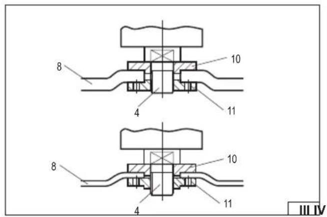
Positioning of the fixing flanges
Note that the discs at the place of fixing to the spindle may be of different thickness.
Depending on the thin abrasive discs used (thickness up to 3.2 mm) or thick ones (thickness over 3.2 mm), the location of the fixing flanges (III) is different. The maximum thickness of the abrasive disc that can be attached to the grinder is 6 mm.
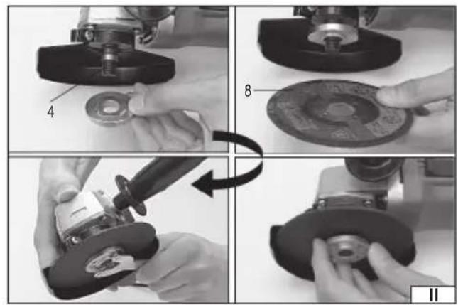
Grinding wheel assembly
Disconnect the supply voltage from the tool. Remove the battery from the tool socket!
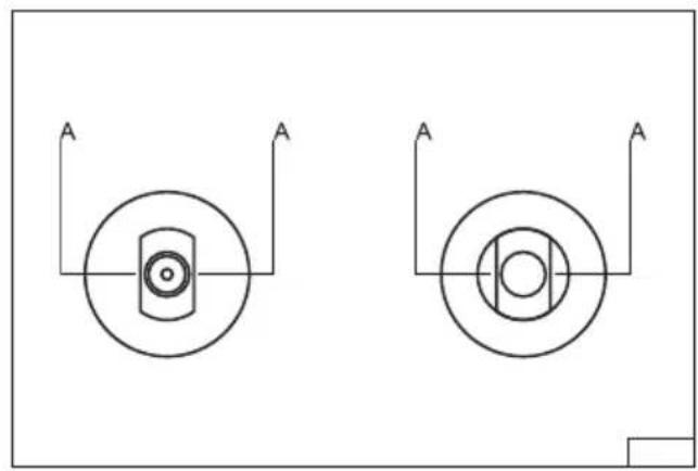
During installation, make sure that the edges A (IV) at the bottom of the spindle tip and the fixing flanges overlap thoroughly.
Place the upper fixing flange on the spindle.
Place the abrasive disc on the spindle and the upper fixing flange
Screw the lower fixing flange on the spindle.
Press the spindle lock and tighten the lower fastening flange with a wrench and then release the pressure on the lock button.
Install the battery, turn the grinder on and observe its operation without any load for about 1 minute.
Remove the battery and check the disc for proper installation.
Removing the abrasive discs
Turn off the grinder and remove the battery from the tool socket.
Press the spindle lock and unscrew the lower fixing flange with the fixing wrench and then remove the abrasive disc from the spindle. Clean the spindle and the fixing flanges of dust and other contaminants generated during operation.
Types of grinding wheels
Any grinding wheel reinforced with a plait intended for use with angle grinders with a permissible circumferential speed of at least 80 m/s and fixing and external diameters specified in the technical data table may be used with the grinder.
If the grinding wheel is provided with a non-threaded hole for its assembly, use the fixing flanges.
It is also possible to assemble wheels with an external diameter specified in the technical data table, equipped with a M14 threaded hole. In this case, do not use fixing flanges and screw the wheel directly to the spindle, locking it with a button, and tightening the wheel firmly and securely using a flat wrench (not included with the grinder).
In the case of wheels enabling the installation of the sandpaper disc with Velcro, only sandpaper discs with the diameter specified in the technical data table should be used. The disc should be placed concentrically on the wheel. The edge of the disc must not project beyond the edge of the wheel.
It is also possible to use diamond grinding wheels with the dimensions specified in the technical data table intended for dry cutting
EN
and grinding. Perform the assembly in the same manner as in the case of grinding wheels. When using diamond segmented discs, the gap between the segments must not exceed 10 mm, measured at the perimeter of the disc, and the segments must have a negative angle of attack.
It is recommended to use grinding wheels made of materials intended for machining a given type of metal. Refer to the documentation provided with the grinding wheel.
Grinding wheels intended for machining stone or diamond grinding wheels for dry working can be used for the machining of ceramic materials.
It is recommended to use wire brushes and sandpaper discs to remove old paint coats from metal parts.
It is forbidden to modify the fixing hole, spindle or use reduction rings to adjust the diameter of the fixing hole to the spindle diameter. It is forbidden to use grinding wheels with a fixing hole diameter other than specified in the technical data table. It is forbidden to use grinding wheels with a cutting chain or cutting discs because they increase the risk of tool kickback towards the operator.
Caution! It is forbidden to use discs other than those allowed for use in this manual, even if they can be assembled on the grinder spindle. Improper discs may not withstand the loads generated during the operation of the angle grinder. Damaged or decaying grinding wheels present a risk of serious injury or death.
CAUTION! All operations mentioned in this chapter must be carried out with the power supply disconnected – the battery must be disconnected from the tool!
USING THE ANGLE GRINDER
Remove the battery from the tool socket!
Before using the tool, check that the housing and battery body are not damaged.
If any damage is visible, it is forbidden to connect the battery to the tool!
Fix the abrasive disc cover and handle.
Never work with the grinder without the abrasive disc guard installed!
Select the type of abrasive disc suitable for the type of operation and install the disc on the grinder spindle.
The workpiece must be secured, e.g. with vices or clamps, in such a manner that it cannot move during work. The grinder disc rotates at a high speed and, if not properly secured, the material may move uncontrollably during work, which would increase the risk of serious injury.
In the case of cutting, support the material being cut on both sides of the cutting line, but in such a way that it does not cause the cutting disc to jam during cutting. Place the supports near the edge of the material being cut and near the cutting line.
Wear eye protection, hearing protectors and protective gloves.
Check that the power switch is in the off position "O". Then connect the battery to the tool.
Keep an appropriate body position to ensure balance and turn the tool on with the switch.
If the power switch is located in the upper or side wall of the grinder body, press the power switch in the rear part of it to turn it on, and then, without releasing the pressure, move it forward in the direction marked with the symbol "l." The power switch may have a hitch that allows it to be locked in this position easier prolonged use. To turn the grinder off, press the power switch on the back of the grinder and allow it to retract. If the power supply is lost while working with the locked power switch, it will only be possible to start work after the power switch has been restored after unlocking and restarting the power switch.
If the grinder is equipped with a power switch located in the lower part of the handle, press and hold the lock button and then press the power switch. Hold the power switch pressed while performing work, but it is not necessary to hold the lock button. Releasing the pressure on the power switch will turn the grinder off. Such a power switch cannot be locked for operation.
Start work by applying the correct surface of the disc to the workpiece:
- when using abrasive discs grind with the side and/or front surfaces,
- in the case of leaf grinding wheels, grind with the side surface so that the sandpaper leaves move parallel to the workpiece,
- in the case of velcro discs enabling the attachment of sandpaper, sanding should be carried out with the side surface,
- in the case of wire brushes, the surface should be worked on with ends of the wires and not with their side surface,
- in the case of cutting discs, cut with the front surface, do not grind with the front surface of the cutting discs.
Speed control (VI)
Speed control is only possible when the supply battery is connected.
Press the button and the lights next to the gear number are illuminated one after another. The higher the number of gears, the higher the speed. Once the highest speed is reached, the next press of the button will shift to the lowest speed gear. Lower gears have lights illuminated in green and higher gears have lights illuminated in red.
The lower speed should be used for brushes and grinding discs made of sandpaper. The high speed should be used for abrasive discs.
When grinding with the side surface, keep the grinder at an angle of not more than 30 degrees from the surface to be worked on (VII). Move the grinder smoothly to and from yourself.
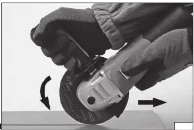
When cutting, the disc should be at a right angle to the cut surface. Do not cut at a different angle. It is forbidden to change the
EN
angle of the cutting disc to the workpiece while cutting. Cut only in a straight line. Failure to follow the above recommendations increases the risk of jamming the cutting disc in the workpiece, which can cause the tool to bounce towards the operator, break the disc or fall apart.
When cutting, guide the grinder towards the rotation of the disc (VIII).
When working with the grinder, do not exert too much pressure on the workpiece and do not make sudden movements in order not to cause jamming or cracking and tearing of the abrasive disc.
Do not overload the tool, the temperature of the external surface must never exceed 60°C.
After finishing work, turn off the grinder, remove the battery and inspect it.
Caution! The disc may be still spinning for some time after turning the grinder off. Wait for the disc to cool down before starting the inspection. During operation, both the disc and the material to be processed can become heated to high temperatures.
Remember! When operating with an angle grinder:
Always use an eye guard.
Do not use abrasive discs with a maximum permissible circumferential speed of less than 80 m/s.
Do not use abrasive discs with a maximum permissible rotational speed of less than the grinder's rotational speed.
ASSEMBLY OF THE ACCESSORIES OF THE STRAIGHT GRINDER
CAUTION! All operations mentioned in this chapter must be carried out with the power supply disconnected – the battery must be disconnected from the tool!
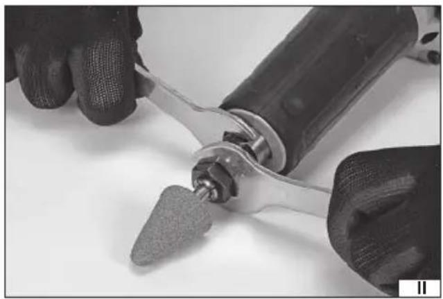
Installation of tooling in the tool chuck (II)
It may be necessary to loosen the fixing nut before inserting a tool into the chuck. To do this, hold the spindle with one spanner and unscrew the nut with the other. The nut should not be completely taken off the chuck.
Place the shank of the tool in the chuck. There must be a gap of no more than 8 mm between the working part of the tool and the chuck. Moreover, make sure that at least half of the tool shank is inside the chuck.
Remove the tooling by by loosening the fixing nut.
Warning! The tooling might be hot immediately after finishing work. Allow it to cool down itself before removing.
Starting and stopping the grinder
Before starting the grinder, hold it with both hands on the handles or isolated housing elements and make sure that the tool does not come into contact with any objects. The direction of rotation of the spindle is indicated by an arrow on the tool housing near the tool chuck.
Start the tool by pressing and holding the back of the on/off button and then sliding it forward (III). The on/off switch can be locked in the front position which can be helpful during prolonged work.
When the tool is started up, hold it in this position for about 30 seconds, watching for any suspicious noises, excessive noise or excessive vibration.
If no signs of malfunction are found, the tool should be switched off by releasing pressure on the switch or, if it was locked, by pressing the back of the switch button. The button retracts automatically, but the tool can still move for some time after the switch is released.
The tool can be put away only after the inserted tool has come to a complete standstill.
Speed control (IV)
Speed control is only possible when the supply battery is connected.
Press the button and the lights next to the gear number are illuminated one after another. The higher the number of gears, the higher the speed. Once the highest speed is reached, the next press of the button will shift to the lowest speed gear. Lower gears have lights illuminated in green and higher gears have lights illuminated in red.
Basic precautions must be taken when using grinding stones. Before each use, the grinding stones should be visually inspected for damage and deformation. It is forbidden to use grinding stones in which any damage has been found. Grinding stones should not be thrown, struck or violently applied to the workpiece. This can cause the grinding stone to disintegrate, resulting in serious injury.
The shank of the tooling must not protrude more than 8 mm from the chuck.
Use accessories according to their intended use. For example, do not grind with discs designed for cutting, do not use drill bits for side milling.
Before fitting the tooling, set the correct operating speed for the type of equipment. After installation, allow the too to reach its full
EN
working speed. Apply only full-speed rotating accessories to the workpiece. Do not apply excessive force, but only as much force as is needed for proper operation. Apply sanding discs at a slight angle to the workpiece. Place the cutting discs perpendicular to the intended cut. Brushes should be applied in such a way that the ends of the wires, not their lateral surfaces, abrade the workpiece.
When finished working, move the accessory safely away from the workpiece, then switch off the power tool and wait for the inserted tool to come to a complete stop. Disconnect the battery from the power tool and proceed with disassembly or adjustment. The workpiece must be clamped or supported in such a way as to prevent uncontrolled movement of the material and its parts while being worked on. This can be done using supports, brackets, clamps, vices, etc. Clamping should be done in such a way as to ensure free access to the work surface.
Always hold the tool with both hands by the insulated handles (V). This will make the work safer and allow easier control of the tool, also during unexpected situations.
Hold the tool with sufficient force to work safely. An overly firm grip can cause fatigue. Avoid holding the tool with your fingers alone.
When using tools screwed onto a threaded shank, they should be selected so that the fixing thread is no longer than the hole into which it will be screwed. This will prevent the accessories from breaking. Stems with flat flanges and without undercuts or recesses should be used. This will increase the contact area between the stem and the accessory and prevent breakage.
Accessories with a diameter larger than that specified in this manual must not be used.
Get to work. In continuous operation, the heat build-up of the grinder and tool should be monitored and breaks should be taken during operation as the temperature rises. To prevent the motor from overheating, it is advisable to take frequent breaks from the grinder and keep the ventilation slots clear.
When working with the grinder, do not exert too much pressure on the workpiece and do not make sudden movements in order not to damage the tool fitted or the grinder itself.
When drilling or milling in steel or aluminium, tools can be cooled with emulsifying oil or coolant recommended for the specific material, while the use of coolant is not recommended when working in brass. In the final phase of drilling through holes, the pressure on the drill bit should be reduced to avoid breaking or jamming. Once the drill is jammed, switch off the tool immediately. Exerting high pressures on the tools, or a wrong choice of speed for the type of work involved, will result in overloading of the tool, which can be recognised by significant heating of the outer surfaces of the tool body.
Do not overload the tool, the temperature of the external surface must never exceed 60°C.
After finishing work, switch off the tool, disconnect the battery and perform maintenance and inspection.
MAINTENANCE AND INSPECTIONS
CAUTION! Before starting adjustment, maintenance or servicing, pull the tool plug out of the mains socket or disconnect the battery from the tool. Having finished working, inspect the power tool for damage by visually checking the exterior and the body and the handles. Check the power cord with plug and its rubber gland or the battery housing, the action of the electric power switch, the ventilation openings for clogging, the motor brushes for sparking, the noise of the bearings and the drive transmission, and how the power tool starts and runs. During the warranty period, the user is not allowed to install any power tools or replace any components or parts, as this will void the warranty rights. Any irregularities found during the inspection or the operation signal the need for repair to be done at the service centre. After finishing work, the housing, ventilation openings, switches, auxiliary handle and covers should be cleaned e.g. with an air jet (with a pressure not exceeding 0.3 MPa), paintbrush or dry cloth without the use of chemicals and cleaning agents. Clean the tools and the handles with a clean dry cloth.
GERÄTEBESCHREIBUNG
Batterie rechargeable
Transport van accu's
DEKLARACJA ZGODNOŚCI DECLARATION OF CONFORMITY DECLARATIE DE CONFORMITATE
1125/YT-828293/EC/2025
We declare and guarantee with full responsibility that the following products:
meet requirements of the following European Standards / Technical Specifications:
EN IEC 62841-2-3:2021 + A11:2021
EN 55014-1:2017 + A11:2020
EN 55014-2:2015
and fulfill requirements of the following European Directives:
2006/42/EC Machinery and safety elements
2014/30/EU Electromagnetic compatibility (EMC) Directive
Directiva privind compatibilitatea electromagnetică (EMC) (H.G. nr. 487/2016)
2011/65/EU Restriction of the Use of Certain Hazardous Substances
Serial number: concern all serials numbers of item(s) mentioned in this declaration
The person authorized to compile the technical file:
DEKLARACJA ZGODNOŚCI DECLARATION OF CONFORMITY DECLARATIE DE CONFORMITATE
1125/YT-82824/EC/2025
We declare and guarantee with full responsibility that the following products:
meet requirements of the following European Standards / Technical Specifications:
and fulfill requirements of the following European Directives:
2006/42/EC Machinery and safety elements
2014/30/EU Electromagnetic compatibility (EMC) Directive
Directiva privind compatibilitatea electromagnetică (EMC) (H.G. nr. 487/2016)
2011/65/EU Restriction of the Use of Certain Hazardous Substances
Serial number: concern all serials numbers of item(s) mentioned in this declaration
The person authorized to compile the technical file:


