
MT 75 MC Slim - Solar panel DOMETIC - Free user manual and instructions
Find the device manual for free MT 75 MC Slim DOMETIC in PDF.

| Product type | Photovoltaic solar panel |
| Brand | Dometic |
| Model | MT 75 MC Slim |
| Nominal power | 75 W |
| Open circuit voltage (Voc) | 21.0 V |
| Short circuit current (Isc) | 4.62 A |
| Cell type | Monocrystalline |
| Number of cells | 36 |
| Dimensions (L x W x H) with brackets | 1200 x 540 x 35 mm |
| Weight | 7.4 kg |
| Operating temperature | -40 °C to 85 °C |
| Maximum relative humidity | 85% |
| Protection rating | IP65 |
| Certifications | CE |
| Use | Mounting on roof of motorhome, caravan, boat |
| Maintenance | Clean with clear water, avoid high-pressure cleaners and abrasive products |
| Safety | Do not touch energized contacts; installation by qualified professional |
Frequently Asked Questions - MT 75 MC Slim DOMETIC
User questions about MT 75 MC Slim DOMETIC
0 question about this device. Answer the ones you know or ask your own.
Ask a new question about this device
Download the instructions for your Solar panel in PDF format for free! Find your manual MT 75 MC Slim - DOMETIC and take your electronic device back in hand. On this page are published all the documents necessary for the use of your device. MT 75 MC Slim by DOMETIC.
USER MANUAL MT 75 MC Slim DOMETIC
natural_image
Technical line drawing of electrical components including cables, connectors, and a panel (no text or symbols)MT 130 CDS, MT 260-2 CDS, MT 210 CDS, MT 420-2 CDS, MT 75 MC Slim Short, MT 150-2 MC Slim, MT 80 MC, MT 160-2 MC, MT 110 MC, MT 220-2 MC, MT 140 MC, MT 280-2 MC, MT 170 MC, MT 340-2 MC, MT 75 MC-80K Slim Short, MT 100 MC-80K, MT 130 MC-80K, MT 150 MC-80K, MT 200 MC-80K
EN Solar System Installation and Operating Manual......
© 0 4 Dometic Group. %he visual appearance of the contents of this manual is protected b' cop' right and design law. %he underl' ing technical design and the products contained herein ma' be protected b' design( patent or pending patent. %he trademarks mentioned in this manual belong to Dometic ) weden * B. * ll rights are reserved.
E ! lish
1 Important notes....
,-planation of s'mbols....
. ) afet' instructions....4
4 ) cope of deliver'.... O
/ *cessories....2
0 Intended 1 se....2
2 %echnical description.... 3
3 Installing the solar s' stem....3
4 Operation....1/
10 5 leaning and maintenance....10
11 %roubleshooting....10
1 Disposal....12
1. 6 arrant'....12
14 %technical data....13
1 Importa t otes
7'lease read these instructions careful' and follow all instructions( guidelines( and warnings included in this product manual in order to ensure that 'ou install( use( and maintain the product proper') at all times. §these instructions M1) % sta' with this product.
B' using the product, 'ou hereb' confirm that 'ou have read all instructions{ guidelines} and warnings careful' and that 'ou understand and agree to abide b' the terms and conditions as set forth herein. You agree to use this product on! for the intended purpose and application and in accordance with the instructions{ guidelines} and warnings as set forth in this product manual as well as in accordance with all applicable laws and regulations. * failure to read and follow the instructions and warnings set forth herein ma' result in an injur' to 'ourself and others{ damage to 'our product or damage to other propert' in the vicinit'. this product manual{ including the instructions{ guidelines} and warnings{ and related documentation{ ma' be subject to changes and updates. : or up-to-date product information{ please visit documents.dometic.com.
2 E. pla atio of symOols
* signal word will identif' safet' messages and propert' damage messages( and also will indicate the degree or level of hazard seriousness.

DAN1 ER2
Indicates a hazardous situation that (if not avoided) will result in death or serious injur'.

3 ARNIN1 2
Indicates a hazardous situation that( if not avoided( could result in death or serious injur' .

CA4TI, N2
Indicates a hazardous situation that (if not avoided) could result in minor or moderate injur'.

N, TICE2
Indicates a situation that (if not avoided) can result in property damage.

N, TE ) complementar' information for operating the product.
3 Safety i str5ctio s
* Iso observe the safet' instructions and stipulations issued b' the vehicle manufacturer and authorized workshops.
361 1 e eral safety

3 ARNIN1 2 Electroc5tio ha7ar8
)olar panels generate direct current and are sources of electricit' when e-posed to sunlight or other light sources. Do not come into contact with the live parts of the solar panel( such as the terminals( as this can result in burns( sparks and fatal shock whether the module is connected or disconnected.
Do not install the solar s' stem when the solar panels are e- posed to sunlight or other light sources. 5 over all solar panels with an opaque cloth or material to prevent the production of electricit' when installing or working with solar panels or wiring.
Installation and removal of the solar s' stem ma' onl' be carried out b' qualified personnel.
Do not operate the solar s' stem if an' component is visibl' damaged.
If this device's power cable is damaged( the power cable must be replaced b' the manufacturer( a service agent or a similar' qualified person in order to prevent safet' hazards.
%he solar s' stem ma' onl' be repaired b' qualified personnel. Improper repairs can lead to considerable hazards.
If 'ou disassemble the device:
- Detach all connections.
- , nsure that no voltage is present on an' of the inputs and outputs.
Onl' use accessories that are recommended b' the manufacturer.
Do not modif' or adapt an' of the components in an' wa'.

3 ARNIN1 2 Ris9 of i :5ry
6 hen e- posed to direct sunlight( the solar panels can heat up to a temperature of up to 20^5 . Do not come into contact with the surface of the solar panels to avoid burns.

3 ARNIN1 2 Health ha7ar8
%his device can be used b' children aged from 3 ' ears and above and persons with reduced ph' sical( sensor' or mental capabilities or lack of e- perience and knowledge if the' have been given supervision or instruction concerning use of the device in a safe wa' and understand the hazards involved.
Electrical 8 devices are ot toys6 * lwa's keep and use the device out of the reach of ver' 'oung children.
5 hildren must be supervised to ensure that the ' do not pla' with the device.
5 leaning and user maintenance shall not be made b' children without supervision.

N, TICE2 Dama! e ha7ar8
, nsure that other objects can or cause a short circuit at the contacts of the device.
, nsure that the negative and positive poles ever come into contact.
Do not step or lean on the solar panels.
Do not put e- cessive load on the glass or back sheet of the solar panels as this ma' break the cells or cause micro cracks.
) tore the solar s' stem in a safe place before mounting or aßer dismounting. 7 protect the solar panels from falling over or down.
362 I stalli ! the 8evice safely

DAN1 ER2 E. plosio ha7ar8
Aever mount the device in areas where there is a risk of gas or dust e-plosion.

3 ARNIN1 2 Ris9 of i :5ry
If 'ou install the solar s' stem on a roof:
- Do not carr' out installation and mounting in strong winds.
- 7protect ' ourself and other persons from falling down. 7revent the possible falling of objects.
•) ecure the work area so that no other person can be injured.

N, TICE2 Dama! e ha7ar8
Improperl' mounted solar panels can get loose and fall down. Do not use silicone or an' other adhesive than the one supplied or recommended one to ensure optimum adhesion.
363 Safety whe co ecti ! the 8evice electrically

3 ARNIN1 2 Electroc5tio ha7ar8
%he electrical installation ma' onl' be connected b' qualified personnel and onl' in accordance with the national regulations. Incorrect connection ma' cause severe hazards.
If 'ou are working on electrical s' stems(ensure that there is somebod' close at hand who can help 'ou in emergencies.
Observe the recommended cable cross-sections.
Ba' the cables so that the' cannot be damaged b' the doors or the hood. 5 rushed cables can lead to serious injur'.

N, TICE2 Dama! e ha7ar8
Do not e-ceed the current and voltage ratings of the solar charger. Onl' install solar panels up to the ma-imum power rating of the used solar charger. If 'our solar s' stem e-ceeds these ratings (contact 'our dealer for a suitable solar charger.
1 se ductwork or cable ducts if it is necessar' to la' cables through metal panels or other panels with sharp edges.
Do ot la' the . 0 C mains cable and the 1 C D5 cable in the same duct.
Do ot la' the cable so that it is loose or heavil' kinked.
: asten the cables securel'.
Do not pull on the cables.
364, perate the 8evice safely

DAN1 ER2 Electroc5tio ha7ar8
Do not touch e-posed cables with 'our bare hands.

3 ARNIN1 2 Ris9 of i :5ry
* t the beginning of each trip and at regular intervals during each trip( check that the solar panels are 8rml' attached to the roof. * n incorrectl' mounted solar panel can fall oD during the journe' and injure other road users.
EN...

CA4TI, N2 E. plosio ha7ar8
Do ot operate the device under the following conditions:
• In the vicinit' of corrosive fumes
- In the vicinit' of combustible materials
- In areas where there is a risk of e-plosions

N, TICE2 Dama! e ha7ar8
* void heav' shocks and vibration while driving.
4 Scope of 8delivery
[]
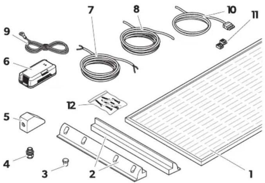
Item Descriptio Q5a tity
1 E1) olar panel
EE
E2) ide roof mounting supl
4 EE
3 Blind plug 1
4 5 able gland 1
5 Foof duct 1
6) olar charge controller 1
7 Outdoor cable 6 - 4 mmHl 1
8 Indoor cable 6 - 4 mmHl 1
9 % temperature sensor
1
10, BB cable kit
1
11 6 *GO connector
12 ) crew *6 0-* -.(4).
10 E
0 EE
| Item Descriptio Q5a tity |
| K Installation and Operating Manual 6digital onl’ | 1 |
| K) hort Installation and Operating Manual 1 |
| K Installation and Operating Manual for the solar charge controller 1 |
E CDS Power 'i eA M% 130 5D) (M% 210 5D)
Blac9'i eA M% 75 M5) lim(M% 80 M5(M% 110 M5(M% 140 M5(M% 170 M5
PowerOlac9li eA M% 75 M5-30L) lim) hort(M% 100 M5-30L(M% 130 M5-30L(M%) 150 M5-30L(M% 200 M5-30L
EE CDS Power 'i eA M% 260-2 5D) (M% 420-2 5D)
Blac9'i eA M% 150-2 M5) lim(M% 160-2 M5(M% 220-2 M5(M% 280-2 M5(M% 340-2 M5
Power0lac9li eA M% 150-2 M5-30L ) lim ) hort( M% 200-2 M5-30L ( M% 260-2 M5-30L ( M% 300-2 M5-30L ( M% 400-2 M5-30L
5 Accessories
* vailable as accessories 6not included in the scope of deliver'
| Desi! atio Ref6 o6 | |
| Dometic %ouch Displa' %D 3. 40 001. 2 |
6 I te 8e8 4se
%he solar s' stem is intended to convert sunlight into direct current [D5] to charge rechargeable 1 C batteries in vehicles or boats while driving or suppl' them with a Moat voltage for power generation. %he batter' power can addition all' be used as a stable power suppl' to operate D5-powered devices connected to the batter'.
%he solar s' stem is suitable for:
• Installation in caravans and motor homes
•) tationar' or mobile use
• , - treme operating conditions (e- pedition use)
• 6 ind speeds up to / kmNh
%he solar s' stem is ot suitable for:
- Mains operation
- 7ortable applications
%he voltage output of connected solar panels ma' not e-ceed the speci8ed ma-imum output of the solar charge controller.
%his product is onl' suitable for the intended purpose and application in accordance with these instructions.
%his manual provides information that is necessary for proper installation and nor operation of the product. 70or installation and nor improper operation or maintenance will result in unsatisfactor performance and a possible failure.
%he manufacturer accepts no liabilit' for an' injur' or damage to the product resulting from:
- Incorrect installation( assembl' or connection( including e- cess voltage
- Incorrect maintenance or use of spare parts other than original spare parts provided b' the manufacturer
- *Iterations to the product without e-press permission from the manufacturer
EN....
- 1 se for purposes other than those described in this manual
Dometic reserves the right to change product appearance and product specifications.
7 Tech ical 8escriptio
%he side roof mounting supports are glued to the vehicle roof without drilling. %he solar panels are screwed onto the side roof mounting supports and are replaceable.
%he wiring to the interior is routed through a pressurized water-tight roof duct.
%he solar s' stem can be e- tended b' further solar panels of the same power. %he single solar panels can be connected to each other at one junction bo-.
%he solar charge controller is connected between the solar panels and the vehicle batteries to ensure the correct charging current of the batteries and to protect the batteries against over voltage and deep discharge.
8 I stalli ! the solar system

3 ARNIN1 2 Electroc5tio ha7ar8
5 oplate1' cover all solar panels with an opaque material during installation to prevent electricit' from being generated.

N, TICE2 Dama! e ha7ar8
, insure that the junction bo- and the roof duct are properl' sealed and that the roof duct is glued tightl' to the roof so that no moisture can leak into the junction bo- or through the roof.
861 I stallatio locatio
6 hen selecting the installation location( consider the following:
- %he mounting surface must be even and stable enough to support the solar panel.
- , nsure that the mounting surface is made of materials that withstand the high temperatures caused b' the solar panel.
- , nsure that the designated mounting surface is suOcientl' dimensioned.
• , nsure there is enough room to access the solar panels and other 8-ed components for future maintenance. - , nsure not to block an' e-isting ventilation openings on the vehicle.
- , nsure that an' e-isting ventilation openings on the vehicle and the rear ventilation of the solar panel are not blocked.
- ) hading can reduce the performance of the solar s' stem. , nsure that 8-ed components( such as air conditioners or opened satellite antennas( do not shade the solar panels.
- 5 choose a location with direct sunlight for optimal performance.
- 7lace several solar panels as close to each other as possible.
- Do not glue the solar panels or roof ducts to rubberized surfaces (e.g. e-terior planking) (as the adhesion of the glue is not guaranteed.
- Do not glue the side roof mounting supports or roof ducts to rubberized surfaces 6e.g. e-terior planking| (as the adhesion of the glue is not guaranteed.
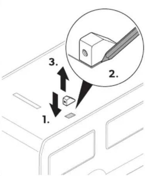
862 Prepari ! the i stallatio
- Mark the bonding surfaces.
□
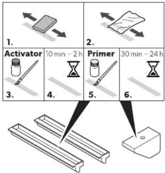
. Grind the bonding surfaces on the vehicle with abrasive Meece.
□
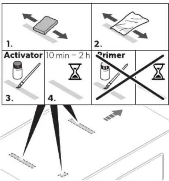
.. 5 lean the bonding surfaces on the vehicle.
- *ppl' the activator to the bonding surface and leave to dr' for 10 min ^1 Q h.
/. Grind the bonding surfaces on the side roof mounting supports and the roof duct with abrasive Meece.
□

flowchart
graph TD
    A["1. Activator"] --> B["2. Paper"]
    B --> C["3. Vessel"]
    C --> D["4. Hourglass"]
    D --> E["5. Printer"]
    E --> F["6. Mask"]
    style A fill:#f9f,stroke:#333
    style B fill:#f9f,stroke:#333
    style C fill:#ccf,stroke:#333
    style D fill:#cfc,stroke:#333
    style E fill:#fcc,stroke:#333
    style F fill:#cff,stroke:#333
- 5 lean the bonding surfaces on the side roof mounting supports and the roof duct.
- * ppl' the activator to the bonding surfaces and leave to dr' for 10 min ^p Q h.
- * ppl' the primer to the bonding surfaces and leave to dr' for . 0 min ^PQ 4 h.
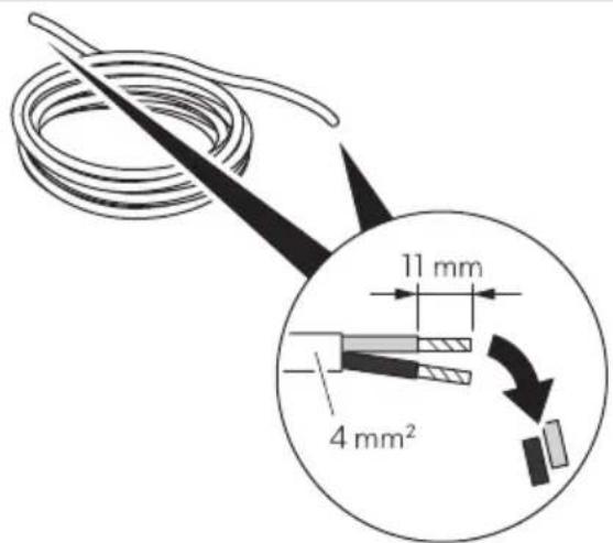
4.) trip the cable ends as follows:
• Outdoor cable 11 mm 64 mmHI
- Indoor cable 11 mm G4 mmHl
□
863 Co ecti ! the solar pa el
Observe the following instructions when connecting the solar panel:
• ) eal the unused cable outlet on the junction bo- 61| with the blind plug 62|.
- Onl' use the outer terminals on the junction bo-.
- Onl' connect solar panels of the same t' pe and capacit'.
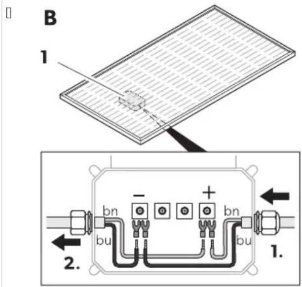
- 5 onnect two solar panels to the one junction bo- closest to the roof duct.
5 onnect the solar panel as follows:
5 connect the outdoor cable to the junction bo-.
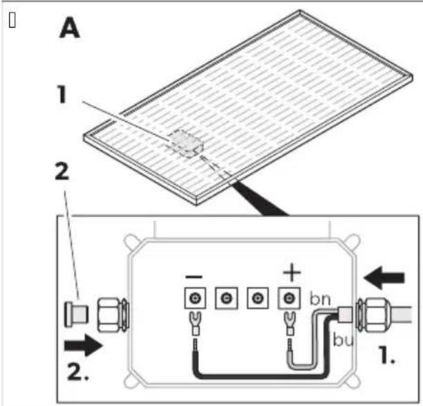
5 onnect several solar panels in parallel:
- 5 connect the positive poles with each other.
- 5 connect the negative poles with each other.
864 Mo5 ti ! the solar system

3 ARNIN1 2 Ris9 of i :5ry
1 se a suitable adhesive( e.g. ) ikame- ^R -//4. Do not use silicone.
Do not move the vehicle until the adhesive is completel' dr' to ensure that the components are 8rml' attached to the vehicle roof. Observe the manufacturer's instructions on the hardening times of the adhesive used.
EN...

N, TICE2 Dama! e ha7ar8
Before drilling an' holes( ensure that no electrical cables or other parts of the vehicle can be damaged b'drilling( sawing or 8ling.
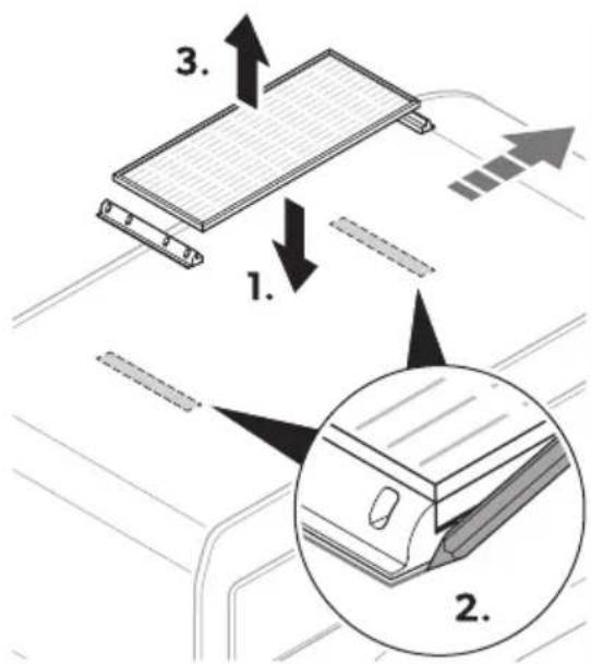
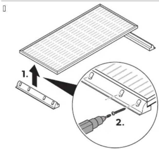
1.) crew the side roof mounting supports to the solar panel.
- * ppl' adhesive to the side roof mounting supports of the solar panel: ig. on page1 (1).
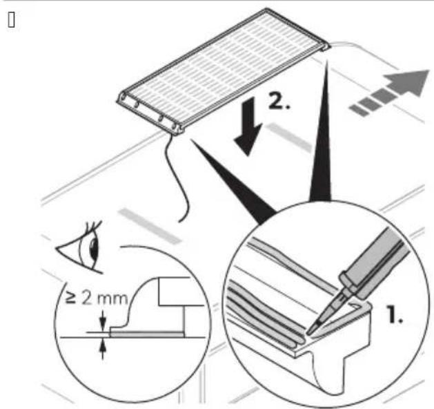
- 7lace the solar panel on the prepared bonding surface on the vehicle G ig. on page1 (21.
- 7ress the side roof mounting supports lightl' against the bonding surface to ensure that the solar panel is 8rml' seated.

N, TICE2 Dama! e ha7ar8
Do not press too hard on the surface of the solar panel.
Do not press on the center of the solar panel.
/. : i- the solar panel e.g. with light weights or adhesive tapel until the adhesive has completel' hardened to ensure that the solar panel rests 8rml' on the surface of the vehicle.

N, TE Observe the manufacturer's instructions on the hardening times of the adhesive used.
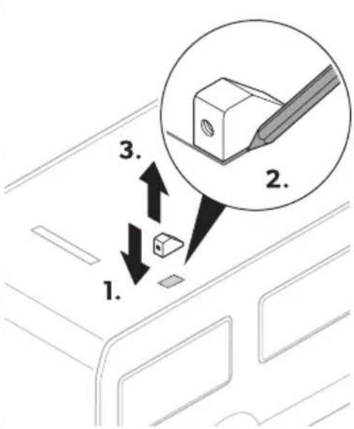
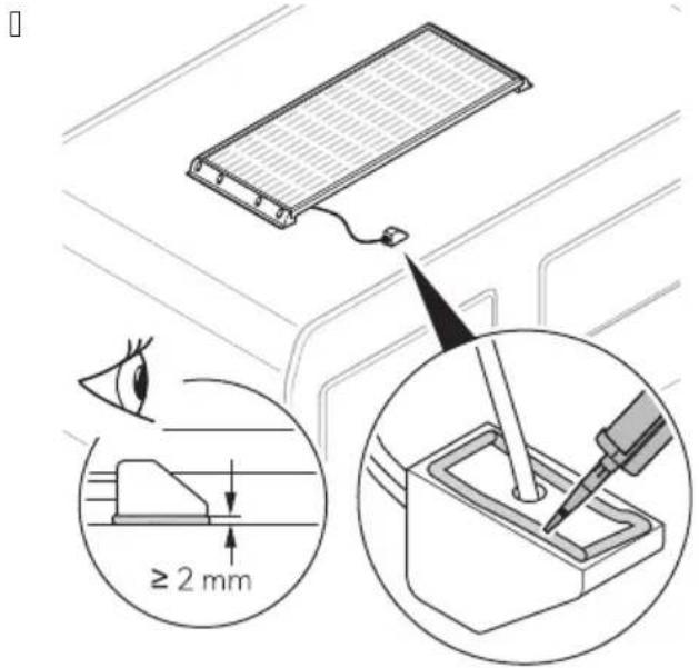
- Foute the connection cable from the junction bo- through the cable gland G ig.PD on page?1. (11.
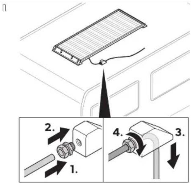
-
Foute the connection cable from the cable gland through the roof duct 6 ig. on page 1. (21.
-
: asten the cable gland onto the roof duct 6 ☐: ig.☐ on page ^2 1. (3l. Observe the necessar' cable length for routing and connecting the cable.
-
Drill a hole into the vehicle surface for the connection cable ☐:ig.☐ on page1. ( 1).
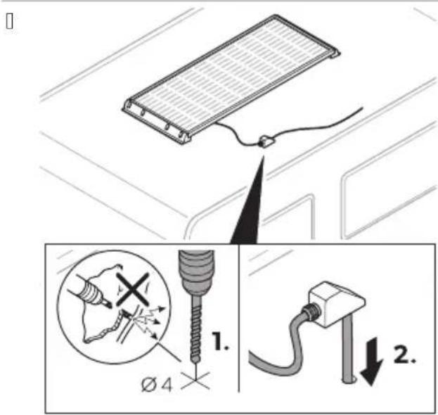
-
Foute the connection cable through the pre-drilled hole into the vehicle interior G: ig. on page1. (2).
-
* ppl' adhesive to the back of the roof duct.
□
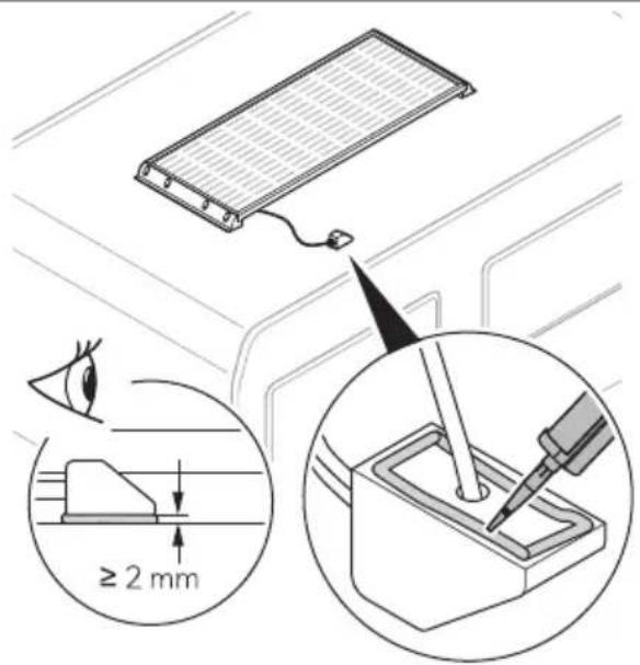
- 7lace the roof duct on the prepared bonding surface on the vehicle.

N, TE Mount the roof duct in the direction of travel of the vehicle to avoid wind and rain loading on the cable gland.
- . : i- the roof duct 6e.g. with adhesive tapel until the adhesive completel' hardened to ensure that the roof duct rests 8rml' on the surface of the vehicle.
□


N, TE Observe the manufacturer's instructions on the hardening times of the adhesive used.
865 Co ecti ! o5t8oor ca0le a 8 i 8oor ca0le

N, TE
%he cable length should be as short as possible.
5 connect the outdoor cable to the indoor cable at a suitable point using the 6 * GO connector §11.
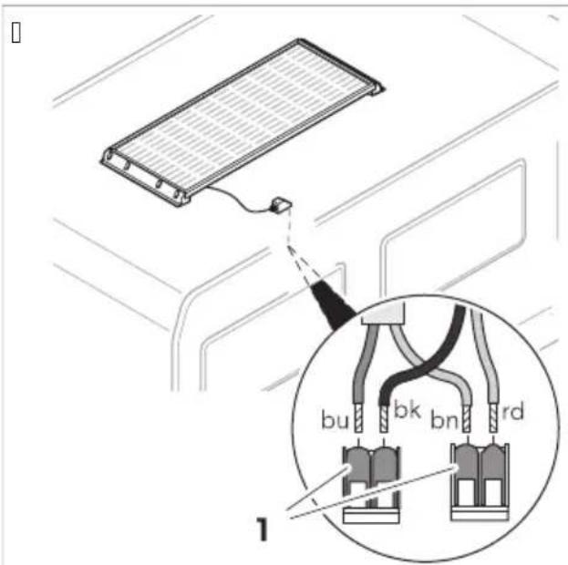
bk black
rd red
bn brown
bu blue
866 Co ecti ! the solar char! e co troller

: ind the information on installing the solar charge controller in the enclosed installation and operating manual or online at qr.dometic.comNbf| 'wD

3 ARNIN1 2
* Iso observe the instructions and safet' precautions for all other components used in the solar s' stem.
9, peratio
For optimal 5se of the solar system, ote the followi ! A
%he solar s' stem generates diDerent amounts of electricit' depending on the amount of sunlight during the da'. %he more sunlight falls on the solar s' stem( the more electricit' is generated.
EN...
%he amount of electricit' generated is aDected b' the following conditions:
- 5 loud' weather
•) easonal solar radiation
• Cariations in the angle of the sun
• ) hading or soiling of the solar s' stem
%he performance of the solar s' stem decreases the more the solar panels heat up. , nsure adequate ventilation and avoid e- cessive solar radiation.
Broken solar panel glass ma' cause electric shock or 8re. %these panels cannot be repaired and should be replaced immediatel'. 5 contact an authorized service agent.

CA4TI, N2 Ris9 of i :5ry
* llow the solar panel to cool down before cleaning to avoid burns or damage to the solar panel as a result of e- cessive temperature diDerences. 5 lean the solar panels in the earl' morning( late afternoon hours or on cloud' da's when the sunlight is low and the solar panels are cooler.

N, TICE2 Dama! e ha7ar8
Do not clean the solar panels with a high-pressure cleaner.
Do not use sharp or hard objects( abrasive cleaning agents or aggressive chemical cleaning agents during cleaning.
Fegularl' check live cables for insulation faults( breaks( rodent damage( weathering and that all connections are tight and corrosion free.
Fegularl' check the surface of the solar panels for cracks and missing or defective components.
: or ma- imum performance keep the solar panel free of dirt and shading( e.g. dust and leaves. Finse the solar panels with a water hose. 5 arefull' remove stubborn dirt with a so□( damp micro8ber cloth or sponge.
Occasionall' check the sealing for an' damage.
11 Tro50leshooti !
| ProOlem Possiole ca5se S5! ! este8 reme8y | ||
| %he solar s' stem does not work no power outputl. | Insulation faults( breaks or loose connections at the live cables. | > 5heck live cables for insulation faults( breaks or loose connections.> 7ull out the fuse on the solar charge controller and check the solar panel voltage Co51 on the solar charge controller.> If ' ou cannot 8nd an error( contact an authorized service agent. |
| :ault' solar charge controller. | Freplace the solar charge controller. | |
| %he solar s' stem does not work properl' low power outputl. | Objects or dirt are blocking out light. 5heck for obstructions and ensure that the solar panels are not blocked b' shadows.> Move the vehicle to a more suitable location. | |
| ProOlem Possiole ca5se S5! ! este8 reme8y | ||
| > Femove an' dirt. | ||
| Overheating of the solar panels. *llow the solar panels to cool down.> Move the vehicle to a more suitable location> , nsure sufficient air circulation around the solar panels. | ||
| One solar panel in the arra' failed. 7ull out the fuse on the solar charge controller and check the solar panel voltage Co51 on the solar charge controller.> 5heck the solar panels for micro cracks.> 5heck the solar panel for delamination.> Feplace the solar panel if neces-sar'. | ||
12 Disposal

Fec' cling packaging material: 7lace the packaging material in the appropriate rec' cling waste bins wherever possible.
If 'ou wish to 8nall' dispose the product( ask 'our local rec' cling center or specialist dealer for details about how to do this in accordance with the applicable disposal regulations. %he product can be disposed free of charge.

If the product contains an' non-replaceable batteries( rechargeable batteries( or light sources( 'ou don't have to remove them before disposal.
13 3 arra ty
%he statutor' warrant' period applies. If the product is defective( please contact the manufacturer's branch in 'our countr' 6see dometic.comNdealerl or 'our retailer.
: or repair and warrant' processing( please include the following documents when ' ou send in the device:
• * cop' of the receipt with purchasing date
• * reason for the claim or description of the fault
A note that self-repair or nonprofessional repair can have safet' consequences and might void the warrant'.
14 Tech ical 8ata
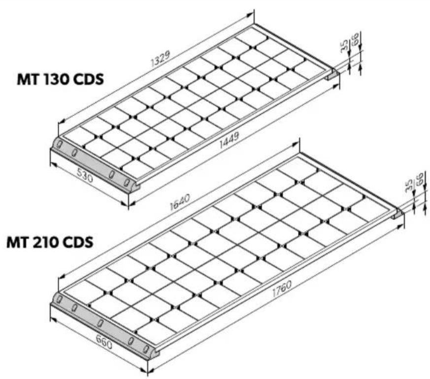
1461 CDS Power 'i e
□
Solar System
| MT 130 CDS MT 260-2 CDS MT 210 CDS MT 420-2 CDS | |||
| Aominal output 66 pl 1.0 00 10 4 0 | |||
| Dail' output 66 hNda'l / 20 1140 4 0 1340 | |||
| Dimensions 66 S D ST I with side roof mounting bracketsl | 1444°S /. 0°S 00 mm | - M% 1.0 5D) 1200°S 000°S 00 mm | - M% 10 5D) |
| :ig.FD on pagef13 | |||
| ) olar panel M%) M 1.0 5D) - M%) M 1.0 5D) | M%) M 10 5D) - M%) M 10 5D) | ||
| ) olar charge controller) 5..0) 5430 | |||
| 6 eight without cablesl | 11.1 kg | 1.1 kg 1/.4 kg | .0.. kg |
| InspectionNcertification | CE | ||
Solar Pa el
| MT SM 130 CDS | MT SM 210 CDS | |
| Aominal output G6 pl | 1.0 | 10 |
| Dail' output G6 hNda'l | /20 | 40 |
| 7ower tolerance | U 10V | |
| MT SM 130 CDS MT SM 210 CDS | ||
| ) hort circuit current [Iscl /.0 * 3.4 * | ||
| Open-circuit voltage [Co5] 4.4 C 4.4 C | ||
| A number of cells 44 44 | ||
| 5 ell t' pe Monocr' stalline | ||
| A normal operating cell temperature [AO5%] | 43°5'U K. °5 | |
| *mbient temperature K | 40°Q 3/°5 | |
| *mbient humidit' ≤ 3/V | ||
| Dimensions 66 S D S T I 1. 4PS /. 0PS . / mm 1040°S 000°S . / mm | ||
| 6 eight 3./ kg 1 ./ kg | ||
| InspectionNcertification | CE | |
%he speci8cations are obtained under the standard test conditions of ) %5 6) %5 : Irradiance 1000 6 NmH( panel temperature /°5 *M 1./l.
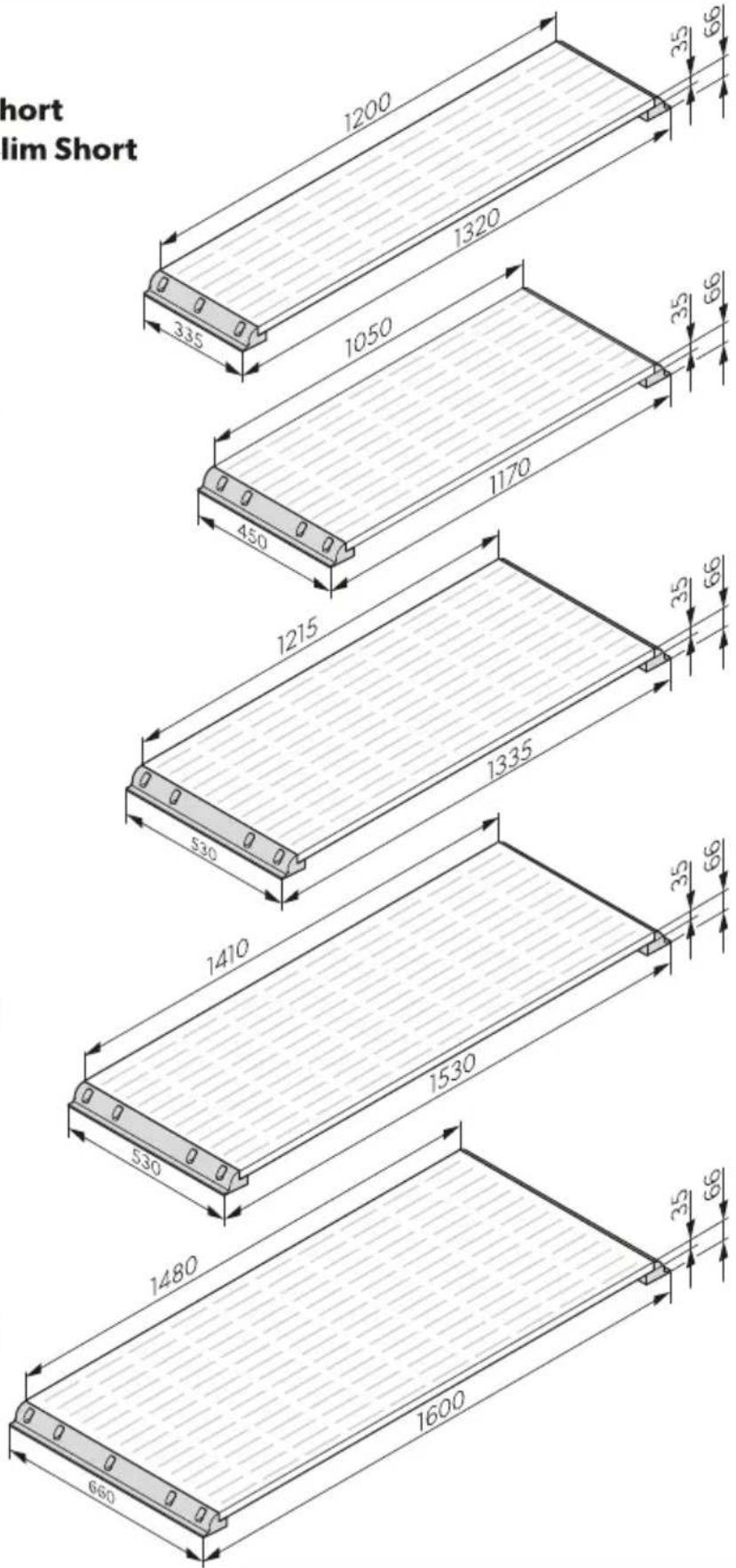
1462 Blac9 'i e
□
MT 75 MC Slim Short
MT 75 MC-80K Slim Short
MT 80 MC
MT 100 MC-80K
MT 110 MC
MT 130 MC-80K
MT 140 MC
MT 140 MC-80K
MT 170 MC
MT 200 MC-80K
Solar System
| MT 75 MC Slim Short MT 150-2 M-C Slim Short | MT 80 MC MT 160-2 MC | |||
| Aominal output 66 pl 2/ | 1/0 30 100 | |||
| Dail' output 66 hNda'l . | 00 000 . 0 040 | |||
| Dimensions 66 S D ST I with side roof mounting bracketsl | 1. 0°S .. /°S 00 mm | - M% 2/ M5 ) lim | 1120°S 4/0°S 00 mm | - M% 30 M5 |
| img:ig.PD on pagef 0 | ||||
| ) olar panel M% ) M 2/ | M5 ) lim ) hort | - M% ) M 2/ M5 ) lim ) hort | M% ) M 30 M5 - M% ) M 30 M5 | |
| ) olar charge controller ) | 5..0) 5..0 | |||
| 6 eight without cablesl | 2.3 kg | 1/ kg | 3./ kg | 10.4 kg |
| InspectionCertification |  | |||
| MT 110 MC | MT 220-2 MC | MT 140 MC | MT 280-2 MC | |
| Aominal output @6 pl | 110 | 0 | 140 | 30 |
| Dail' output @6 hNda'l 440 330 /00 11 0 | ||||
| Dimensions @6 S D ST I with side roof mounting bracketsl | 1. . /PS /. 0°S 00 mm | - M% 110 M5 | 1/. 0PS /. 0PS 00 mm | - M% 140 M5 |
| :ig.# on page# 0 | ||||
| ) olar panel | M%) M 110 M5 | - M%) M 110 M5 | M%) M 140 M5 | - M%) M 140 M5 |
| ) olar charge controller ) 5..0) 5..0 | ||||
| 6 eight without cablesl | 10. kg | 14.4 kg | 11.0 kg | .2 kg |
| InspectionCertification |  | |||
| MT 170 MC | MT 340-2 MC | |
| Aominal output Ⓤ6 pl | 120 | .40 |
| Dail' output Ⓤ6 hNda'l | 030 | 1.00 |
| Dimensions Ⓤ6 S D S T I with side roof mounting bracketsl | 1000°S 000°S 00 mm | - M% 120 M5 |
 | ||
| ) olar panel | M%) M 120 M5 | - M%) M 120 M5 |
| ) olar charge controller | ) 5430 | |
| 6 eight without cablesl | 14.1 kg | 2.2 kg |
| Inspection\certification |  | |
Solar Pa el
| MT SM 75 M-C Slim Short | MT SM 80 MC MT SM 110 MC MT SM 140 MC MT SM 170 MC | ||||
| Aominal output66 pl | 2/30 110 140 120 | ||||
| Dail' output 66 hNda'l | .00.0440 /00 030 | ||||
| 7ower tolerance U 10V | |||||
| )hort circuit current Iscl | 4..2* | 4.2* | 0.0* | 2./* | 10..* |
| Open-circuit voltage Co5l | 1.0C | 1.0C | 1.0C | 4.3C | ..C |
| Aumber of cells | 2 2 2 | 2 2 | |||
| 5ell t' pe | Monocr' stalline | ||||
| Aormal operating cell temperatureGAO5%I | 43°5PUK.°5 | ||||
| *mbient temperature | K40°Q 3/°5 | ||||
| *mbient humidit' | ≤3/V | ||||
| Dimensions 66 SD ST I | 1 00PS../PS./mm | 10/0PS4/0PS./mm | 1 1/PS/.0S./mm | 1 1/PS/.0S./mm | 1430PS000PS./mm |
| 6 eight | /.4 kg | 0.kg | 2.0 kg | 4kg | 11.kg |
| Inspection Ncertifi-cation | CE | ||||
%he speci8cations are obtained under the standard test conditions of ) %5 G) %5: Irradiance 1000 6 NmH( panel temperature /°5 * M 1./l.
1463 Power0lac9li e
Solar System
| MT 75 M-C-80K Slim Short | MT 150-2 M-C-80K Slim Short | MT 100 MC-80K | MT 200-2 MC-80K | |
| Aominal output 66 pl 2/ | 1/0 | 100 | 00 | |
| Dail' output 66 hNda'l | ..0 | 000 | 440 | 330 |
| Dimensions 66 S D S T I with side roof mounting bracketsl | 1. 0°S .. /°S 00 mm | - M% 2/ M5) lim ) hort | 1120°S 4/0°S 00 mm | - M% 30 M5 |
 | ||||
| ) olar panel | M%) M 2/M5) lim ) hort | - M%) M 2/M5) lim ) hort | M%) M 100 M5 | - M%) M 100 M5 |
| ) olar charge controller | ) 5..0 | ) 5..0 | ||
| 6 eight without cablesl | 2.3 kg | 1/ kg | 3./ kg | 10.4 kg |
| MT 75 M-C-80K Slim Short | MT 150-2 M-C-80K Slim Short | MT 100 MC-80K MT 200-2 MC-80K | |
| InspectionNcertification |  | ||
| MT 130 MC-80K MT | 260-2 MC-80K MT 150 MC-80K MT 300-2 MC-80K | ||
| Aominal output 66 pl 1.0 | 00 1/0 . 00 | ||
| Dail' output 36 hNda'l /2 | 1144 000 1. 0 | ||
| Dimensions 36 S D S T I with side roof mounting bracketsl | 1. . /°S /. 0°S 00 mm | - M% 1. 0 M5 | 1/. 0°S /. 0°S 00 mm - M% 1/0 M5 |
 | |||
| ) olar panel M%) M 1. 0 | M5 - M%) M 1. 0 M5 | M%) M 1/0 M5 - M%) M 1/0 M5 | |
| ) olar charge controller ) 5..0 ) 5..0 | |||
| 6 eight without cablesl | 10. kg | 14.4 kg | 11.0 kg .2 kg |
| InspectionNcertification |  | ||
| MT 200 MC-80K MT 400-2 MC-80K | |||
| Aominal output 66 pl | 00 | 400 | |
| Dail' output 36 hNda'l | 330 | 1200 | |
| Dimensions 36 S D S T I with side roof mounting bracketsl | 1000°S 000°S 00 mm | - M% 00 M5 | |
 | |||
| ) olar panel | M%) M 120 M5 | - M%) M 120 M5 | |
| ) olar charge controller | ) 5430 | ||
| 6 eight without cablesl | 14.1 kg | 22 kg | |
| InspectionNcertification |  | ||
Solar Pa el
| MT SM 75 M-C-80 Slim Short | MT SM 100 M-C-80 | MT SM 130 M-C-80 | MT SM 150 M-C-80 | MT SM 200 M-C-80 | |
| Aominal output66 pl | 2/ 100 | 1. 0 | 1/0 | 00 | |
| Dail' output 66 hN da'l | .. 0 | 440 | /2 | 000 | 330 |
| 7ower tolerance | U 10V | ||||
| )hort circuit current GIscl | ../ * | 4 * | /.2 * | 0.0 * | 3.3 * |
| Open-circuit voltage Co5l | 0.40 C | 204 C | 24/ C | 204 C | 24/ C |
EN...
| MT SM 75 M-C-80 Slim Short | MT SM 100 M-C-80 | MT SM 130 M-C-80 | MT SM 150 M-C-80 | MT SM 200 M-C-80 | |
| Aumber of cells 30 30 30 30 30 | |||||
| 5ell t' pe Monocr' stalline | |||||
| Aormal operating cell temperature [AO5%] | 43°5PUK.°5 | ||||
| *mbient tempera-ture | K40°Q 3/°5 | ||||
| *mbient humidit' ≤ 3/V | |||||
| Dimensions 66 S D S T I | 1 00PS . . /PS . / mm | 10/0PS 4/0°S . / mm | 1 1/PS /. 0°S . / mm | 1410FS /. 0°S . / mm | 1430FS 000FS . / mm |
| 6 eight | /.4 kg | 0. kg | 20 kg | 4 kg | 11. kg |
| InspectionNcertifi-cation |  | ||||
%he speci8cations are obtained under the standard test conditions of ) %5 6) %5: Irradiance 1000 6 NmH( panel temperature /°5 * M 1./l.
1464 Solar char! e co troller

: ind detailed information on the technical data of the solar charge controller in the enclosed installation and operating manual or online at qr.dometic.com\be.c-d.
De5tsch
Positio Beschrei05 ! A 7ahl
bk) chwarz
rd Fot
bn Braun
bu Blau
866 Solarla8ere! ler a schlieEe

KII me t Descriptio Q5a titl
| MT 130 CDS MT 260-2 CDS MT 210 CDS MT 420-2 CDS | |
| 5 ontrgleNcertification | CE |
Pa ea5 solaire
Articolo Descri7io e Q5a titN
Nr6 Beschri:vi ! Aa tal
1 E1 Xonnepaneel
EE
Arti9el Bes9rivelse A tal
1 E1) olpanel
EE
E2 %agmonteringsstotte(sic
4 EE
3 Blp ndprop 1
4 Labelforskruning 1
5 %agkanal 1
Del Bes9riv i ! MC ! 8
1 E1) olpanel
EE
E2 MonteringsstYd sidotak
4 EE
3 Blindplugg 1
4 7ackbo-1
5 %akledning 1
6) olladdare 1
- Dra anslutningskabeln genom det fYrborrade holet in i fordonet 6 bild.∅ sida ^2 140(21.
- *pplicera lim pq baksidan av kabelkanalen.

1 .) Wtt takkanalen pq den fYrberedda fwst' tan pq fordonet.

PASS PS2 Fare for s9a8er
PASS PS2 Fare for s9a8er
PASS PS2 Fare for s9a8er
Ikke overskrid solcelleladerens nominelle strom eller spenning. Installer bare solcellepaneler opptil den nominelle maksimaleDekten for solcelleladeren. T vis solcelleanlegget overskrider disse verdiene: %a kontakt med forhandleren din for q anskaDe en egnet solcellelader.
Bruk tomme ror eller ledningsgjennomforinger nqr ledninger mq fores gjennom platevegger eller andre vegger med skarpe kanter.
199e legg . 0°C-nettledningen og 1 °C-likestromsledningen i den samme ledningskanalen.
I99e legg ledningene lost eller med skarpe bo' er.
: est kablene sikkert.
Ikke trekk i kablene.
364 Si99erhet ve8 Or59 av apparatet

FARE2 Fare for ele9tris9 stQt
PASS PS2 Fare for s9a8er
Eleme t Bes9rivelse A tall
| 1 E1) olcellepanel | |
| EE | |
| E2) idestotte for takmonter | |
| 4 EE | |
| 3 Blindplugg 1 | |
| 4 7akknippel 1 | |
| 5 %akgjennomforing 1 | |
| 6 Baderegulator for solcelleanlegg 1 | |
| 7 1 tendorskabel 6 - 4 mmH 1 | |
| 8 Innendorskabel 6 - 4 mmH 1 | |
| 9 %emperatursensor | 1 |
| 10 , BB-kabelsett | 1 |
| 11 6 *GO-tilkobling | |
| 12 ) krue *6 0-* -. (4) . | 10 E |
| 0 EE |
PASS PS2 Fare for s9a8er
. 7uss limoverMatene pq kjoreto' et med slipeMeece.
□

.. Fengjor limoverMatene pq kjoreto' et.
4. 7qfor aktivatoren på limoverMaten( og la det torke i 10 min)Q h.
/. 7uss limoverMatene pq sidestottene for takmontering og takgjennomforingen med slipeMeece.
□
flowchart
graph TD
    A["1. Activator"] --> B["2. Paper"]
    B --> C["3. Vessel"]
    C --> D["4. Hourglass"]
    D --> E["5. Printer"]
    E --> F["6. Mask"]
    style A fill:#f9f,stroke:#333
    style B fill:#f9f,stroke:#333
    style C fill:#ccf,stroke:#333
    style D fill:#cfc,stroke:#333
    style E fill:#fcc,stroke:#333
    style F fill:#cff,stroke:#333
O. Fengjor limoverMatene pq sidestottene for takmontering og takgjennomforingen.
2. 7qfor aktivatoren pq limoverMatene( og la det torke i 10 min ^P Q h.
3. 7qfor grunningen pq limoverMaten( og la det torke i . 0 min ^2 Q 4 h.
4. *visoler kabelendene som folger:
PASS PS2 Fare for s9a8er
PASS PS2 Fare for s9a8er
- Begg tilkoblingskabelen gjennom det borede hullet inn i kjoreto' et 6 8g.20 pq sidef103(2l.
- 7qfor lim pq baksiden av takgjennomforingen.
- 7lasser takgjennomforingen pq den klargjorte limoverMaten pq kjoreto' et.

bk svart
rd rod
bn brown
[brunl]
bu blue 3blql
866 Til9o0li ! av la8ere! 5latore for solcellea le!! et

Du 8nner informasjon om installasjon av solcelleladeren i den medfolgende monterings- og bruksanvisningen( eller pq nettet pq qr.dometic.comNbfJ 'wD

ADVARSE'2
PASS PS2 Fare for s9a8er
dometic.com/sales-offices


