Colony Soft T975500.002 - Shower system American Standard - Free user manual and instructions
Find the device manual for free Colony Soft T975500.002 American Standard in PDF.


User questions about Colony Soft T975500.002 American Standard
0 question about this device. Answer the ones you know or ask your own.
Ask a new question about this device
Download the instructions for your Shower system in PDF format for free! Find your manual Colony Soft T975500.002 - American Standard and take your electronic device back in hand. On this page are published all the documents necessary for the use of your device. Colony Soft T975500.002 by American Standard.
USER MANUAL Colony Soft T975500.002 American Standard
Thank you for selecting American-Standard...the benchmark of fine quality for over 100 years. To ensure that your installation proceeds smoothly—please read these instructions carefully before you begin.
natural_image
Illustration of four different kitchen faucet fixtures (no text or symbols)Certified to comply with ANSI A112.18.1 U.S. Patent No. D403,750
M968757D
1
SPOUT INSTALLATION
CAUTION
Turn off hot and cold water supplies before beginning.
■ Complete FINISHED DECK (A) before trim installation.
■ Turn off the water supplies.
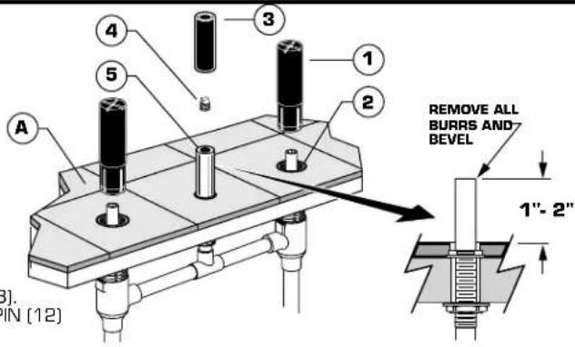
■ Remove the GUARDS (1) from the VALVE BODIES (2). Remove the SPOUT GUARD (3) and 1/4" PLUG (4) from the SPOUT SHANK (5)
The SPOUT SHANK (6) height should be 1" to 2" above the FINISHED DECK (A). Cut the SPOUT SHANK (5) if necessary. Remove all burrs and bevel the end of the shank. Failure to do so may damage the SPOUT O-ring during installation and cause water leakage.
Drill a 3/16" HOLE (C) in the finished deck. See TEMPLATE for location.
■ Lubricate the SPOUT O-RING (6)
■ Remove the PLUG BUTTON [7] from the SPOUT [8].
■ Position the RUBBER RING [9] in the GROOVE [B] in the base of the SPOUT [8]. Push the SPOUT [8] down onto the SPOUT SHANK [5] and align the SPOUT PIN [12] with the 3/16" DRILLED HOLE (C) in the FINISHED DECK (A).
- Tighten the SET SCREW (10) securely with the 5mm HEX KEY (11).
- Insert the PLUG BUTTON (7) into the SPOUT (8).
text_image
4 3 1 2 5 A REMOVE ALL BURRS AND BEVEL 1"- 2" 3). IN (12)ARMADO DE LA LLAVE
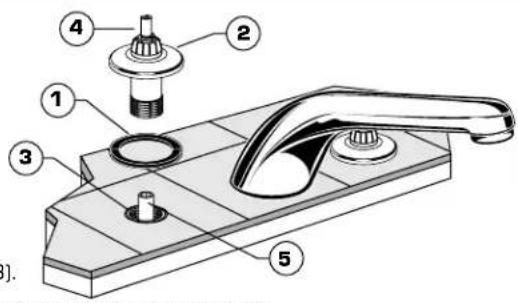
■ Fit ESCUTCHEON SEALS (1) into underside of VALVE ESCUTCHEONS (2).
Thread the VALVE ESCUTCHEONS (2) into the VALVE BODIES (3). Align the HANDLE STEM (4) with the SLEEVE (5) as necessary. Thread the VALVE ESCUTCHEON (2) into the BODIES (3) until the ESCUTCHEON (2) contacts the finished deck.
text_image
Technical diagram of a kitchen sink with numbered parts for identificationJUEGO DE ESCUDETE
■ Turn HANDLE STEM (1) to "OFF" position.
■ Place the HANDLE ADAPTER (2) on the HANDLE STEM (1). Install the ADAPTER SCREW (3) and tighten securely.
■ Position LEVER HANDLE (4) and place on ADAPTER (2). Install the HANDLE SCREW (5) and tighten securely.
text_image
Diagram of a kitchen sink with numbered parts for identification4
INSTALL ACRYLIC HANDLE TRIM
■ Turn HANDLE STEM (1) to "OFF" position.
■ Place the HANDLE ADAPTER [2] on the HANDLE STEM (1).
■ Position ACRYLIC HANDLE (3) and install on ADAPTER (2). Install the HANDLE SCREW (4) and tighten securely.
■ Push in INDEX BUTTON (5). [Hot-left side, Cold-Right side]
INSTALE LAS MANIJAS ACRÍLICAS
text_image
Exploded view diagram of a mechanical component with numbered parts for identificationM968757D
5
TEST INSTALLED FAUCET
■ Remove STREAM STRAIGHTENER (1). With handles in OFF position, turn on water supplies and check all connections for leaks.
■ Operate both handles to flush water lines thoroughly. Replace STREAM STRAIGHTENER [1].
PRUEBA DE LA LLAVE INSTALADA
text_image
Technical diagram of a bathroom sink with labeled parts and directional arrows indicating flow or movement.6
If faucet drips proceed as follows:
■ Stream straightener may accumulate dirt causing distorted and reduced water flow. Remove aerator and rinse clean.
If spout drips, operate handles several times from OFF to ON position. Do not force-handles turn only 90°.
CARE INSTRUCTIONS:
DO: SIMPLY RINSE THE PRODUCT CLEAN WITH CLEAR WATER. DRY WITH A SOFT COTTON FLANNEL CLOTH.
DO NOT: DO NOT CLEAN THE PRODUCT WITH SOAPS, ACID, POLISH, ABRASIVES, HARSH CLEANERS, OR A CLOTH WITH A COARSE SURFACE.
Product names listed herein are trademarks of American Standard Inc.
M968757D
American Standard
COLONY SOFT DECK MOUNT TRIM KIT JUEGO DECORATIVO PARA CUBIERTA COLONY TROUSSE DE GARNITURE POUR MONTAGE SUR PLAGE D'ÉVIER COLONY

text_image
MODEL NUMBER NÚMERO DE MODELO NUMÉRO DE MODÈLE T975.400BP T975.400 T975.500BP T975.500 M918504-0070A SCREW Tornillo VIS M908423-0070A ACRYLIC HANDLE Maneral Acrilico POIGNÉE ACRYLIQUE M916803-YYY0A METAL LEVER HANDLE MANIJA METÁLICA POIGNÉE MÉTALLIQUE PLEINE M918075-0070A HANDLE SCREW TORNILLO DE LA MANIJA VIS DE LA POIGNÉE M961461-YYY0A BUTTON AND SCREW BOTON Y TORNILLO BOUTON ET VIS M918504-0070A SCREW TORNILLO VIS M918021-0070A ADAPTER ADAPTAR APPROPRIER M961640-YYY0A SPOUT BOQUILLA BEC 028678-0070A STREAM STRAIGHTENER REGULADOR DE CHORRO DE AGUA REDRESSEUR DE JET M961460-0020A VALVE ESCUTCHEON KIT JUEGO DE ESCUDETE KIT D'ÉCUSSONReplace the "YYY" with appropriate finish code
| CHROME, CROMO, CHROME | 002 |
| POLISHED BRASS, BRONCE PULIDO, LAITON POLI | 099 |
American Standard
DECK MOUNT TUB FILLERS
Installation Instructions T990.5XX
COLONY DIVERTER & PERSONAL SHOWER TRIM KIT
Thank you for selecting American-Standard...the benchmark of fine quality for over 100 years.
To ensure that your installation proceeds smoothly—please read these instructions carefully before you begin.
natural_image
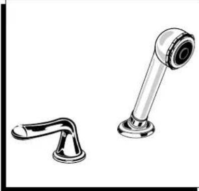
Illustration of two bathroom fixtures: a handle and a showerhead (no text or symbols)Certified to comply with ANSI A112.18.1 U.S. Patent No. D403,750 M968762
text_image
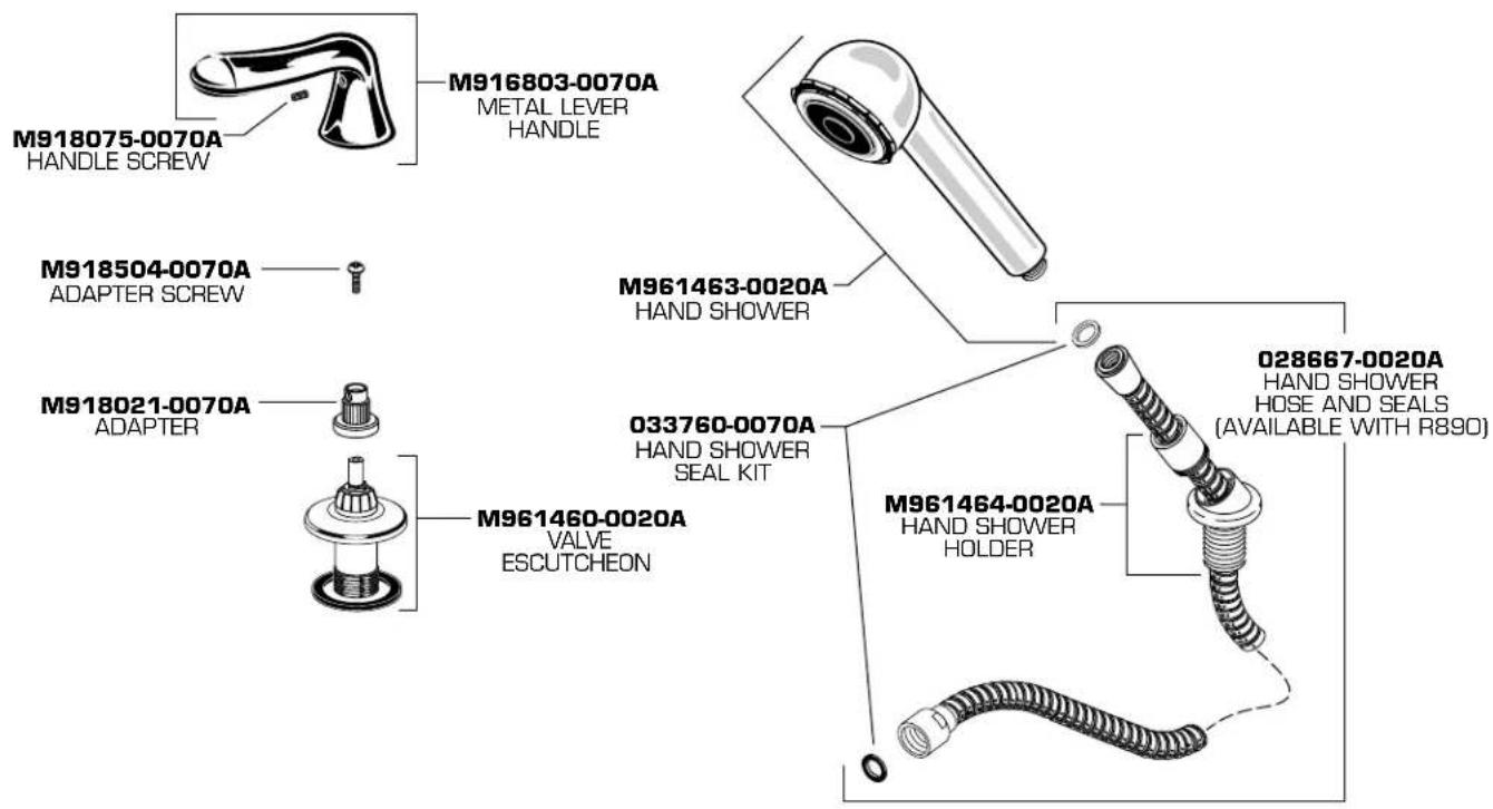
M918075-0070A HANDLE SCREW M916803-0070A METAL LEVER HANDLE M918504-0070A ADAPTER SCREW M918021-0070A ADAPTER M961463-0020A HAND SHOWER 033760-0070A HAND SHOWER SEAL KIT M961460-0020A VALVE ESCUTCHEON M961464-0020A HAND SHOWER HOLDER 028667-0020A HAND SHOWER HOSE AND SEALS (AVAILABLE WITH R890)1 INSTALL DIVERTER VALVE TRIM
■ REMOVE THE DIVERTER GUARD.
■ Place the ESCUTCHEON SEAL over the DIVERTER BODY.
Thread the VALVE ESCUTCHEON into the DIVERTER BODY. Align the HANDLE STEM with the SLEEVE as necessary. Thread the VALVE ESCUTCHEON into the BODY until the ESCUTCHEON contacts the finished deck.
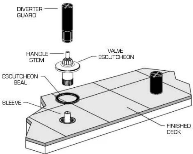
text_image
DIVERTER GUARD HANDLE STEM VALVE ESCUTCHEON ESCUTCHEON SEAL SLEEVE FINISHED DECK2
INSTALL HANDLE TRIM
■ Turn HANDLE STEM fully clockwise (Tub Filler position).
■ Place the HANDLE ADAPTER on the HANDLE STEM. Install the ADAPTER SCREW and tighten securely.
■ Position LEVER HANDLE and place on ADAPTER. Install the HANDLE SCREW and tighten securely.
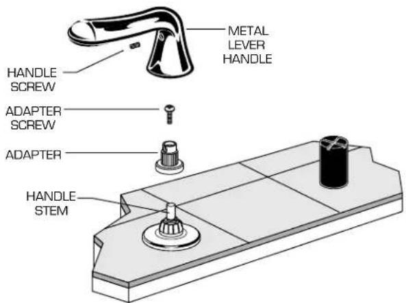
text_image
METAL LEVER HANDLE HANDLE SCREW ADAPTER SCREW ADAPTER HANDLE STEM3
INSTALL HAND SHOWER
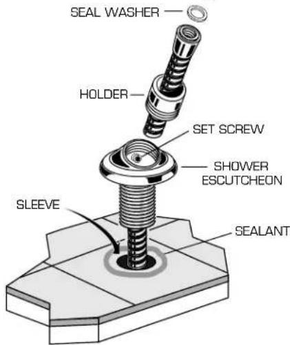
■ Unscrew the HOLDER from the SHOWER ESCUTCHEON. Slip the SHOWER HOSE through the HOLDER and the SHOWER ESCUTCHEON. Insert a SEAL WASHER into the SHOWER HOSE CONNECTOR.
■ Pull out the SLEEVE GUARD and HOSE. Unthread the SLEEVE GUARD from the HOSE END connection. Be careful not to allow the HOSE to fall back through the SLEEVE.
■ Thread the SHOWER HOSE onto the HOSE END connection and tighten securely.
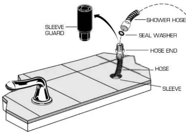
text_image
SLEEVE GUARD SHOWER HOSE SEAL WASHER HOSE END HOSE SLEEVE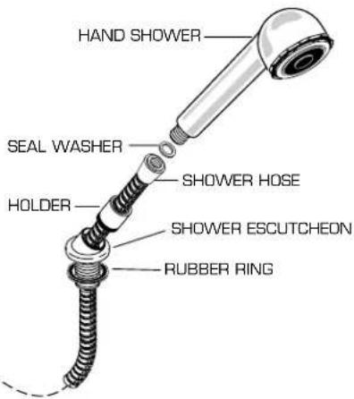
text_image
HAND SHOWER SEAL WASHER HOLDER SHOWER HOSE SHOWER ESCUTCHEON RUBBER RING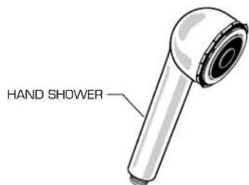
text_image
HAND SHOWER■ Apply a sealant around the HOSE HOLE.
■ Thread the SHOWER ESCUTCHEON into the SLEEVE until the ESCUTCHEON contacts the finished deck.
■ Loosen the SET SCREW in the SHOWER ESCUTCHEON and rotate the ESCUTCHEON towards the center of the tub. Retighten the SET SCREW.
■ Thread the HOLDER into the SHOWER ESCUTCHEON.
■ Insert a SEAL WASHER into the SHOWER HOSE connector and connect the HAND SHOWER. Place the HAND SHOWER into the HOLDER.

HOTLINE FOR HELP
For toll-free information and answers to your questions, call:
1 (800) 442-1902
Weekdays 8:00 a.m. to 7:00 p.m. Eastern Time
IN CANADA 1-800-387-0369 (TORONTO 1-905-306-1093)
text_image
SEAL WASHER HOLDER SET SCREW SHOWER ESCUTCHEON SLEEVE SEALANTM968762
American Standard
DECK MOUNT TUB SYSTEMS ROUGH VALVE KIT
Installation Instructions R800 SERIES R810 SERIES
Thank you for selecting American-Standard... the benchmark of fine quality for over 100 years.
To ensure that your installation proceeds smoothly—please read these instructions carefully before you begin.
text_image
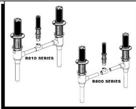
R810 SERIES R800 SERIESCertified to comply with ANSI A112.18.1
U.S. Patent No. D403,750
M968650C
1 ROUGHING-IN
text_image
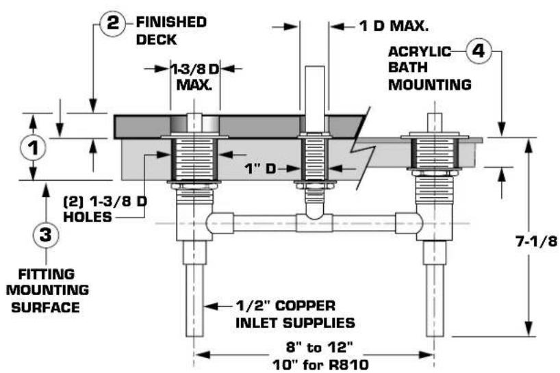
FINISHED DECK 1-3/8 D MAX. 1 D MAX. ACRYLIC BATH MOUNTING (2) 1-3/8 D HOLES 1" D FITTING MOUNTING SURFACE 1/2" COPPER INLET SUPPLIES 8" to 12" 10" for R810 7-1/8- DECK THICKNESS TOTAL DECK THICKNESS UP TO 2-1/2"
- FINISHED DECK FINISHED DECK VARIABILITY ACCOMMODATES DECKING MATERIAL (TILE, MARBLE, CORIAN®...) TO 1" THICK
- FITTING MOUNTING SURFACE ADJUSTABILITY, TO 1-1/2" THICK
- ACRYLIC BATHS ADJUSTABILITY, TO 1-1/2" THICK
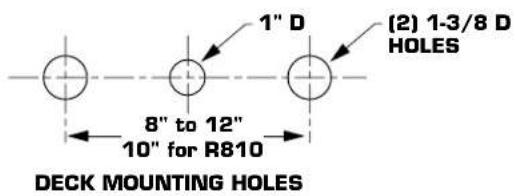
text_image
1" D (2) 1-3/8 D HOLES 8" to 12" 10" for R810 DECK MOUNTING HOLES2 MOUNT SPOUT SHANK
- Drill holes in mounting deck as shown. The maximum allowable deck thickness is 1-1/2".
■ Insert the SPOUT SHANK through the mounting deck from below. Assemble the SPOUT SHANK LOCK RING so it is flush with the top of the threads on the SHANK.
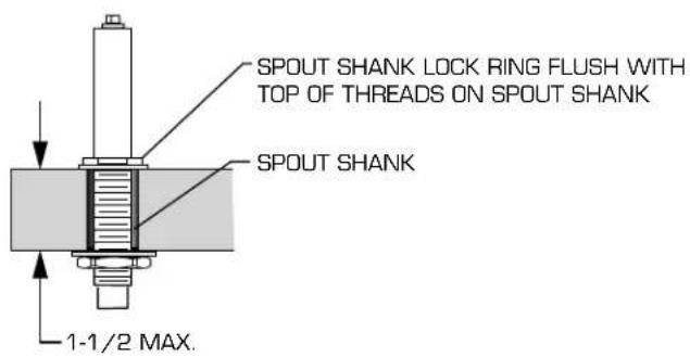
text_image
SPOUT SHANK LOCK RING FLUSH WITH TOP OF THREADS ON SPOUT SHANK SPOUT SHANK 1-1/2 MAX.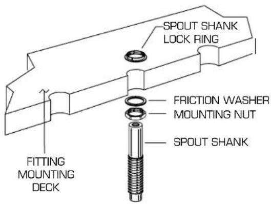
text_image
SPOUT SHANK LOCK RING FITTING MOUNTING DECK FRICCTION WASHER MOUNTING NUT SPOUT SHANK3
MOUNT VALVE BODIES
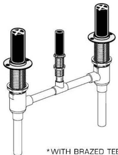
- Cut the copper outlet tubes of the VALVE BODIES as required. (Not necessary for R810).
■ Insert the HOT and COLD VALVE BODIES into the TEE. (Not necessary for R810). The HOT VALVE BODY is marked with a red label.
■ Insert the VALVE BODIES and TEE through the mounting deck from below. Assemble the VALVE LOCK RINGS so they are flush with the top of the VALVE BODIES.
■ Insert the SPOUT SHANK into the TEE. (Not necessary for R810).
■ Tighten the VALVE BODY and SHANK MOUNTING NUTS securely.
■ Fasten the VALVE LOCK RING to the wooden mounting surface with #8 screws (not provided).
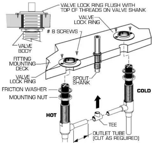
text_image
VALVE LOCK RING FLUSH WITH TOP OF THREADS ON VALVE SHANK8 SCREWS
VALVE LOCK RING VALVE BODY FITTING MOUNTING DECK VALVE LOCK RING SPOUT SHANK FRICTION WASHER MOUNTING NUT COLD HOT TEE OUTLET TUBE (CUT AS REQUIRED)4
SOLDER CONNECTIONS
■ Connect the water supply lines to the copper inlet tubes of the VALVE BODY.
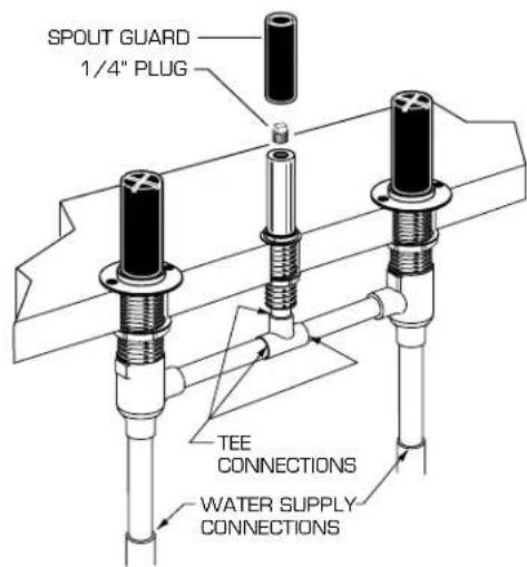
■ Solder all TEE and WATER SUPPLY CONNECTIONS.
■ Remove the GUARD from the SPOUT SHANK. Assemble the 1/4" PLUG to the SPOUT SHANK with a thread sealant.
■ Turn on the water supplies and check all connections for leakage.
■ Replace the GUARD on the SPOUT SHANK. Turn off the water supplies.
text_image
SPOUT GUARD 1/4" PLUG TEE CONNECTIONS WATER SUPPLY CONNECTIONS5
SERVICE
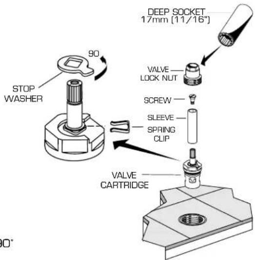
TO CHANGE THE DIRECTION OF HANDLE ROTATION
■ Turn off the water supplies.
■ Turn HANDLE to the off position.
■ Unscrew the VALVE LOCK NUT and remove. A 17mm deep socket is required.
■ Remove the CARTRIDGE by pulling upon the SLEEVE.
■ Remove the SLEEVE from the CARTRIDGE.
■ Remove the SPRING CLIP.
■ Remove the STOP WASHER. Turn it 90° and replace.
■ Replace the SPRING CLIP.
■ Reverse the above steps to reassembly the components.
If the spout drips, operate the handles several times from the off to the on position. Do not force - the handles only turn 90°
text_image
STOP WASHER 90° DEEP SOCKET 17mm [11/16"] VALVE LOCK NUT SCREW SLEEVE SPRING CLIP VALVE CARTRIDGEAmerican Standard
DECK MOUNT TUB SYSTEMS
MODEL NUMBERS
R800 R810
text_image
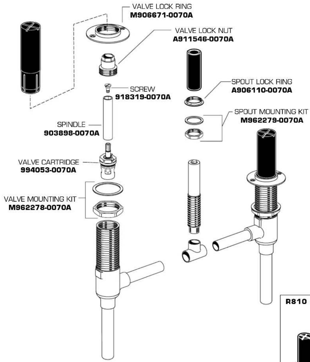
VALVE LOCK RING M906671-0070A VALVE LOCK NUT A911546-0070A SCREW 918319-0070A SPINDLE 903898-0070A VALVE CARTRIDGE 994053-0070A VALVE MOUNTING KIT M962278-0070A SPOUT LOCK RING A906110-0070A SPOUT MOUNTING KIT M962279-0070A R810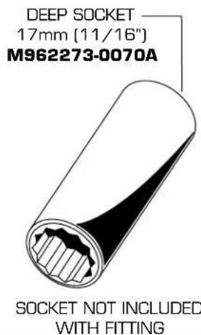
text_image
DEEP SOCKET 17mm (11/16") M962273-0070A SOCKET NOT INCLUDED WITH FITTINGR810 SERIES
natural_image
Technical diagram of a three-pin electrical connector with threaded leads and terminal posts (no text or symbols)
HOTLINE FOR HELP
For toll-free information and answers to your questions, call:
1 (800) 442-1902
Weekdays 8:00 a.m. to 7:00 p.m. Eastern Time
IN CANADA 1-800-387-0369 (TORONTO 1-905-306-1093)
Product names listed herein are trademarks of American Standard Inc.
©American Standard Inc. 2003
American Standard
DECK MOUNT TUB FILLERS
Installation Instructions R890 SERIES
DIVERTER & PERSONAL SHOWER ROUGH VALVE KIT
Thank you for selecting American-Standard...the benchmark of fine quality for over 100 years.
To ensure that your installation proceeds smoothly-please read these instructions carefully before you begin.
natural_image
Technical illustration of a mechanical connector with two cylindrical components and connecting hoses (no text or symbols)Certified to comply with ANSI A112.18.1
U.S. Patent No. D403,750
M968355D
1 ROUGHING-IN
text_image
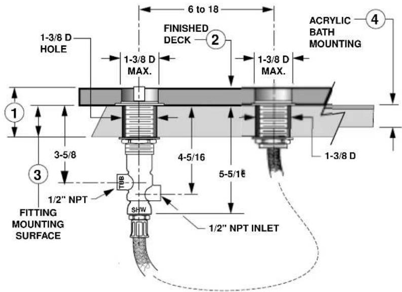
6 to 18 FINISHED DECK 2 1-3/8 D MAX. 1-3/8 D HOLE ACRYLIC BATH MOUNTING 4 1-3/8 D MAX. 1-3/8 D 3-5/8 4-5/16 5-5/16 1/2" NPT FITTING MOUNTING SURFACE SHW 1/2" NPT INLET1. DECK THICKNESS
TOTAL DECK THICKNESS UP TO 2-1/2"
2. FINISHED DECK
FINISHED DECK VARIABILITY ACCOMMODATES DECKING MATERIAL (TILE, MARBLE, CORIAN®...) TO 1" THICK
3. FITTING MOUNTING SURFACE
ADJUSTABILITY, TO 1-1/2" THICK
4. ACRYLIC BATHS
ADJUSTABILITY, TO 1-1/2" THICK
text_image
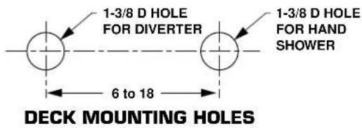
1-3/8 D HOLE FOR DIVERTER 1-3/8 D HOLE FOR HAND SHOWER 6 to 18 DECK MOUNTING HOLES2 LOCATION OF R890 WHEN USED WITH R800
text_image
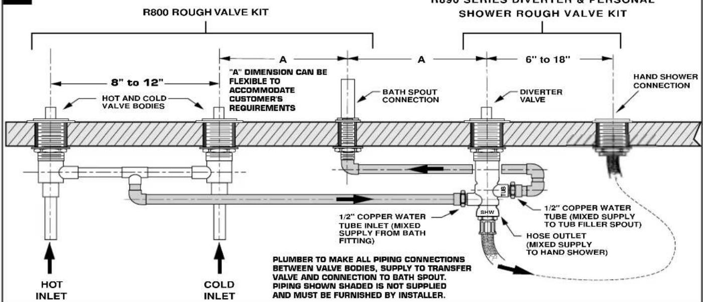
R800 ROUGH VALVE KIT "A" DIMENSION CAN BE FLEXIBLE TO ACCOMMODATE CUSTOMER'S REQUIREMENTS HOT AND COLD VALVE BODIES BATH SPOUT CONNECTION 6" to 18" HAND SHOWER CONNECTION 1/2" COPPER WATER TUBE INLET (MIXED SUPPLY FROM BATH FITTING) 1/2" COPPER WATER TUBE (MIXED SUPPLY TO TUB FILLER SPOUT) HOSE OUTLET (MIXED SUPPLY TO HAND SHOWER) HOT INLET COLD INLET PLUMBER TO MAKE ALL PIPING CONNECTIONS BETWEEN VALVE BODIES, SUPPLY TO TRANSFER VALVE AND CONNECTION TO BATH SPOUT. PIPING SHOWN SHADED IS NOT SUPPLIED AND MUST BE FURNISHED BY INSTALLER.3
INSTALLATION
NOTE: Use thread sealant on all threaded connections.
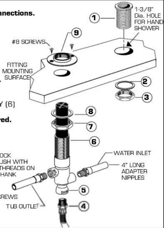
■ Drop the SLEEVE (1) into the hole in the mounting deck.
■ Assemble the WASHER (2) and LOCKNUT (3) to the SLEEVE (1) and tighten securely.
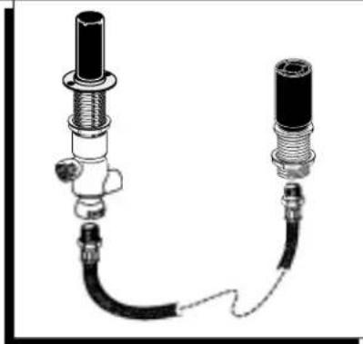
For copper water tube installations, make two 4" long adapter nipples (1/2" Male NPT x 1/2" CWT). Thread nipples into the inlet and tub outlet of the DIVERTER BODY. Tighten connections securely. Do Not Solder these Connections on the DIVERTER BODY. Damage may occur.
Thread HOSE (4) into the SHOWER CONNECTION (5) of the DIVERTER BODY (6) and tighten securely. Check with local plumbing codes for backflow prevention requirements. Install a backflow prevention device if required.
■ Assemble MOUNTING NUT (7) and WASHER (8) onto DIVERTER BODY (6).
■ Insert the DIVERTER BODY (6) through the mounting deck from below.
Assemble the VALVE LOCK RING (9) so it is flush with the top of the DIVERTER BODY (6).
■ Position the DIVERTER BODY (6) as required and tighten the MOUNTING NUT (7) securely.
■ Fasten the VALVE LOCK RING (9) to the wooden mounting surface with #8 screws (not provided).
■ Connect the water inlet and tub outlet lines to the DIVERTER BODY (6).
text_image
connections. #8 SCREWS FITTING MOUNTING SURFACE (6) ed. OCK PUSH WITH THREADS ON HANK CREWS TUB OUTLET 1-3/8" Dia. HOLE FOR HAND SHOWER 2 3 4 5 6 7 8 SHW WATER INLET 4" LONG ADAPTER NIPPLES4
TEST Note: Test Cap not provided.
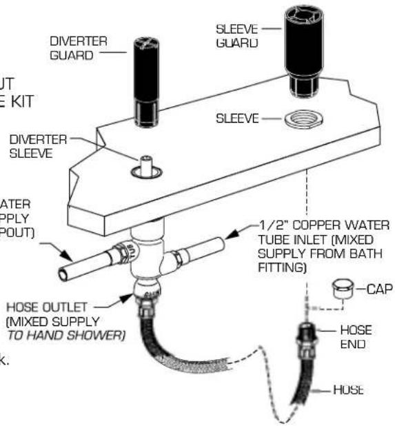
■ Cap the HOSE OUTLET. Remove the DIVERTER GUARD.
■ Remove the SPOUT GUARD. Assemble the 1/4" PLUG to the SPOUT SHANK with a thread sealant. See the R800 SERIES ROUGH VALVE KIT instructions for details.
■ Turn on the water supplies.
■ Rotate the DIVERTER SLEEVE back and forth fully. Check all connections for leakage.
■ Turn off the water supplies. Replace the DIVERTER GUARD and the SPOUT GUARD. Remove the CAP from the HOSE OUTLET.
text_image
OUT E KIT DIVERTER SLEEVE WATER SUPPLY PAYOUT) HOSE OUTLET (MIXED SUPPLY TO HAND SHOWER) 1/2" COPPER WATER TUBE INLET (MIXED SUPPLY FROM BATH FITTING) CAP HOSE END HUSE5
HOSE
■ Insert the HOSE through the SLEEVE from below the mounting deck.
- Thread the SLEEVE GUARD onto the HOSE END connection.
■ Insert the SLEEVE GUARD into the SLEEVE.
6
SERVICE
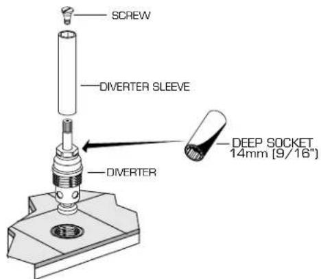
TO REMOVE DIVERTER
■ Turn off the water supplies.
■ Turn HANDLE to the off position.
■ Remove the SLEEVE from DIVERTER by losing screw.
■ Using 14mm (9/16") Deep Socket, remove diverter.
text_image
SCREW DIVERTER SLEEVE DIVERTER DEEP SOCKET 14mm [9/16"]M968355D
American Standard
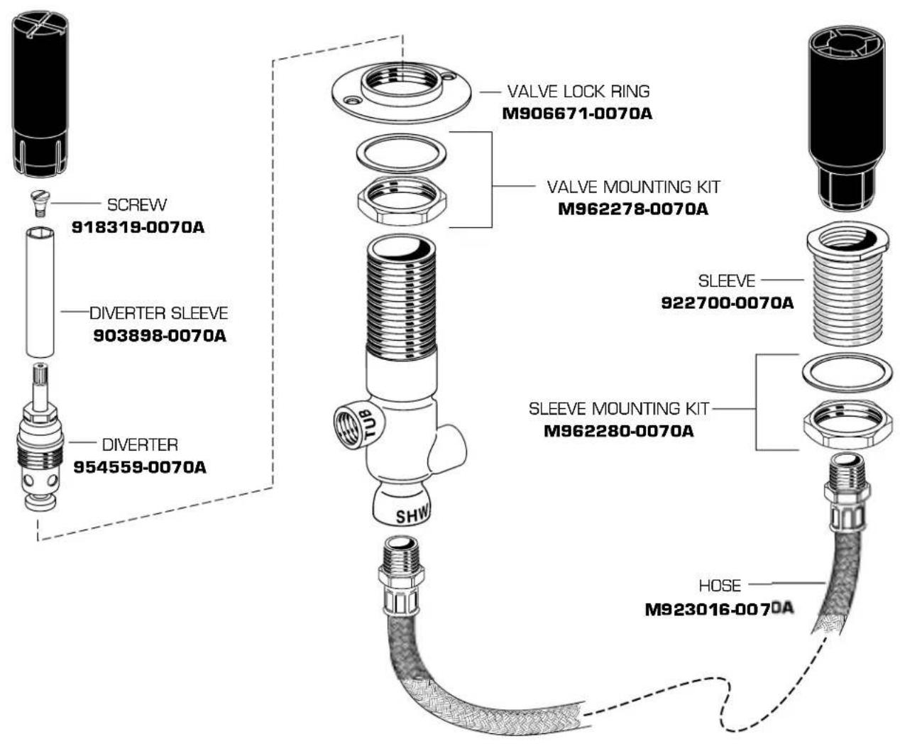
DIVERTER & PERSONAL SHOWER ROUGH VALVE KIT
MODEL NUMBER
R890
text_image
SCREW 918319-0070A DIVERTER SLEEVE 903898-0070A DIVERTER 954559-0070A VALVE LOCK RING M906671-0070A VALVE MOUNTING KIT M962278-0070A SLEEVE 922700-0070A SLEEVE MOUNTING KIT M962280-0070A SHW HOSE M923016-0070A
HOT LINE FOR HELP
For toll-free information and answers to your questions, call:
1-800 442-1902
Weekdays 8:00 a.m. to 8:00 p.m. EST
IN CANADA 1-800-387-0369 [TORONTO 1-905-306-1093]
Weekdays 8:00 a.m. to 7:00 p.m. EST
IN MEXICO 01-800-839-12-00
Product names listed herein are trademarks of American Standard Inc
© American Standard Inc. 2004