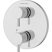
Serin TU064740.002 - Faucets American Standard - Free user manual and instructions
Find the device manual for free Serin TU064740.002 American Standard in PDF.


| Product Type | Balanced pressure shower valve with diverter |
| Brand | American Standard |
| Model | Serin TU064740.002 |
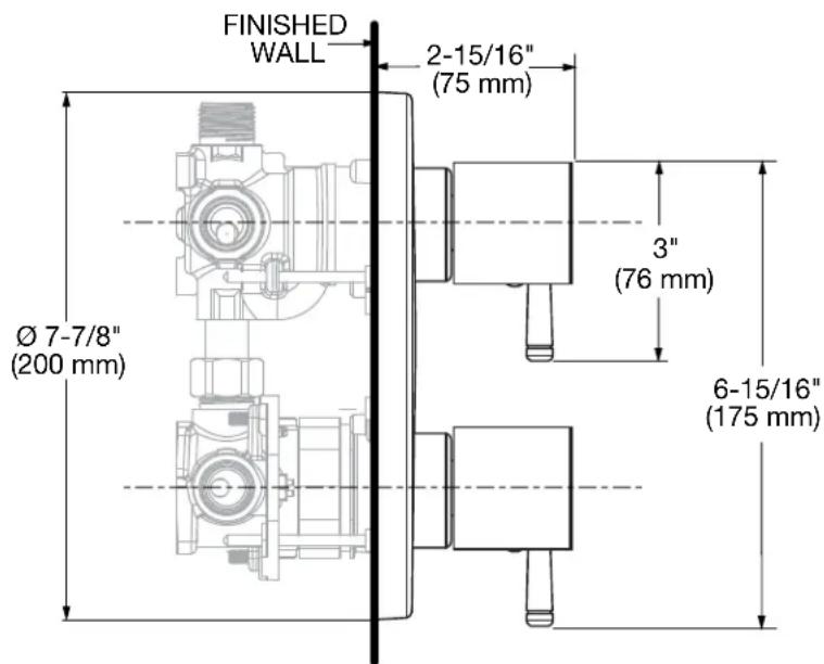
| Rough-in dimensions | Depth: 75 mm (2-15/16 in), diameter: 200 mm (7-7/8 in) |
| Supply | Hot and cold water, balanced pressure |
| Primary functions | Two handles, integrated 2 or 3-way diverter, adjustable anti-scald device |
| Care and cleaning | Clean with a soft cloth and mild detergent; avoid abrasive and acidic products |
| Safety | Anti-scald device (temperature limiter) certified ANSI A112.18.1M |
| Spare parts | Cartridges, handles, adapters, screws, caps, hex key |
| Repairability | Replaceable cartridges, back-to-back installation possible |
| Recommended tools | Phillips screwdriver, flathead screwdriver, hex key |
| Certification | ANSI A112.18.1M |
Frequently Asked Questions - Serin TU064740.002 American Standard
User questions about Serin TU064740.002 American Standard
0 question about this device. Answer the ones you know or ask your own.
Ask a new question about this device
Download the instructions for your Faucets in PDF format for free! Find your manual Serin TU064740.002 - American Standard and take your electronic device back in hand. On this page are published all the documents necessary for the use of your device. Serin TU064740.002 by American Standard.
USER MANUAL Serin TU064740.002 American Standard
natural_image
Technical line drawing of a mechanical flange assembly with bolted components (no text or symbols)Certified to comply with ANSI A112.18.1M
Serin®
Flash™ 2-Handle Integrated Diverter Pressure Balance Valve Trim
Thank you for selecting American Standard... the benchmark of fine quality for over 100 years.
To ensure that your installation proceeds smoothly-please read these instructions carefully before you begin.

Phillips Screwdriver

Flat Blade Screwdriver
RECOMMENDED TOOLS
ROUGHING-IN DIMENSIONS
text_image
FINISHED WALL 2-15/16" (75 mm) Ø 7-7/8" (200 mm) 3" (76 mm) 6-15/16" (175 mm)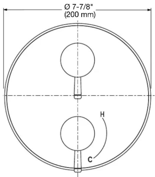
text_image
Ø 7-7/8" (200 mm) H CCARE INSTRUCTIONS:
- To keep your new faucet looking new, please follow these simple care instructions:
DO: - Simply rinse the faucet clean with clear water. - Dry the faucet with a soft cotton cloth.
DO NOT:
- Do not use any abrasive cleaners, cloths, or paper towels.
- Do not use any cleaning agents containing acids, polish abrasives, or harsh cleaners or soaps.
- Regular and routine cleaning will reduce the need for heavy cleaning and polishing. If heavy cleaning is required, the following procedures are recommended:
- Remove as much surface dirt and film using clear water and soft cotton cloth (as described above).
- Use any of the following to remove tough surface film and build-up:
- Mild liquid detergents
– Clear ammonia free liquid glass cleaners - Non-acidic, non-abrasive gentle liquid or fully dissolved powder cleansers mixed according to manufacturers directions
– Non-abrasive liquid polishers
- Once clean, rinse faucet again with clear water to thoroughly remove cleaner or polish and blot dry with a soft cotton cloth.
Failure to follow these care instructions may damage the Faucet's finish.
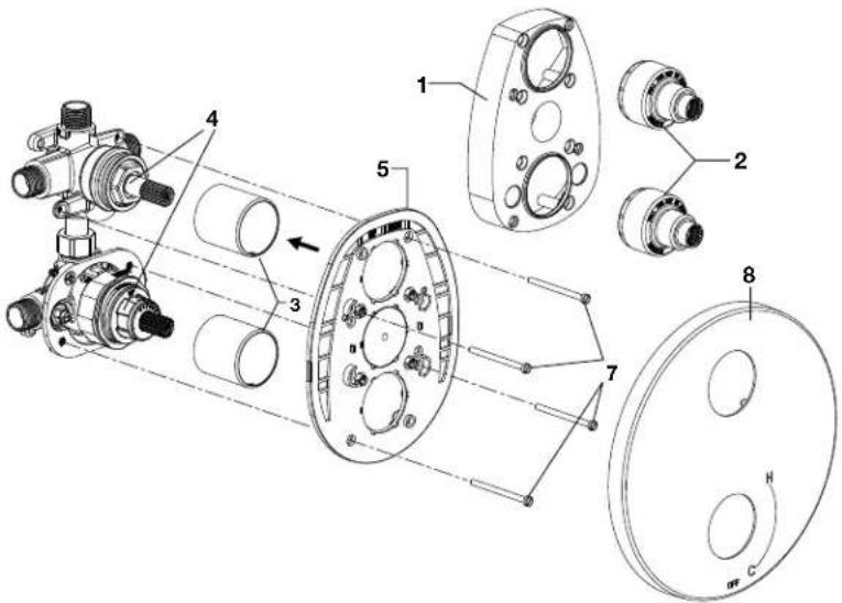
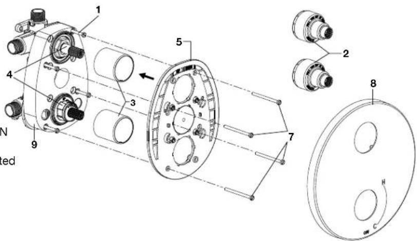
1 TRIM INSTALLATION
- Remove PLASTER GUARD (1) and the two CARTRIDGE COVERS (2).
- Push two CARTRIDGE SLEEVES (3) over the cartridges on VALVE BODY (4).
- Push ESCUTCHEON HOLDER (5) over CARTRIDGE SLEEVES (3).
- Insert four SCREWS (7) through ESCUTCHEON HOLDER (5) and thread in VALVE BODY (4) where indicated by a dashed line.
- Push ESCUTCHEON (8) on to ESCUTCHEON HOLDER (5) until they are secured with the snap fitting.
text_image
Technical diagram of a mechanical assembly with numbered components and labeled parts2 TRIM INSTALLATION FOR THIN WALL
- Remove the two CARTRIDGE COVERS (2).
- Push two CARTRIDGE SLEEVES (3) over the cartridges on VALVE BODY (4).
- Remove the four PLASTER GUARD SCREWS (1).
- Push ESCUTCHEON HOLDER (5) over CARTRIDGE SLEEVES (3).
- Insert four SCREWS (7) through ESCUTCHEON HOLDER (5), and PLASTER GUARD (9) and thread in to the VALVE BODY (4) where indicated by a dashed line.
- Push ESCUTCHEON (8) on to ESCUTCHEON HOLDER (5) until they are secured with the snap fitting.
text_image
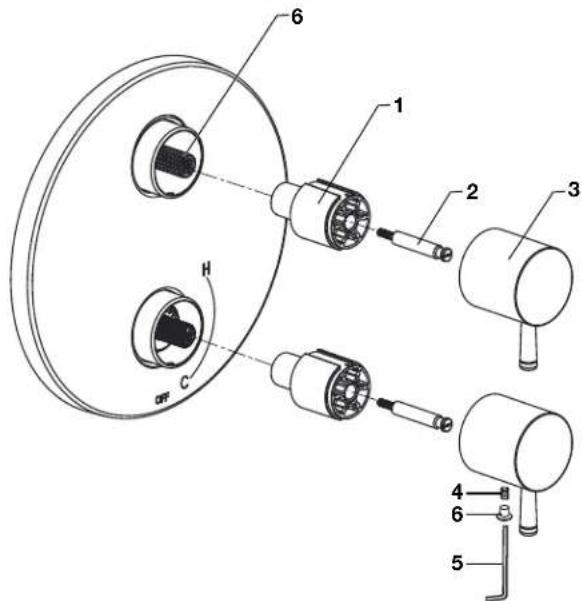
1 2 3 4 5 6 7 8 9 N ed3 HANDLE INSTALLATION
- Push the two HANDLE ADAPTERS (1) on to VALVE STEMS (6) and secure with HANDLE ADAPTER SCREWS (2).
- Push the two HANDLES (3) over HANDLE ADAPTERS (1).
- Secure the two HANDLES (3) with SET SCREW (4) and the provided HEX WRENCH (5).
- PushCOVERCAP(6) into SET SCREW (4).
NOTE: Adjust the orientation of HANDLE ADAPTER (1) to align handles at the 6 o'clock position as pictured.
text_image
Technical diagram of a mechanical assembly with numbered components, likely a valve or pump assembly.SERVICE
CAUTION
Turn off hot and cold water supplies before beginning.
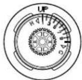
ADJUST HOT LIMIT STOP
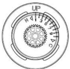
- By restricting HANDLE rotation and limiting the amount of hot water allowed to mix with the cold, the HOT LIMIT SAFETY STOP (1) reduces risk of accidental scalding. To set the maximum hot water temperature of your faucet valve, adjust the setting on the HOT LIMIT SAFETY STOP (1).
- Turn CARTRIDGE STEM (2) to the OFF position (coldest setting) before making adjustment to HOT LIMIT STOP (1). Pull forward and rotate counterclockwise one number to limit hot water temperature. Use NUMBERS (5) on CARTRIDGE (4) on HOT LIMIT STOP (1) for indication.
text_image
UP H 1 3 5 7 9 11 13 15 17 19 21 23 25 27 29 31 33 35 37 39 41 43 45 47 49 51 53 55 57 59 61 63 65 67 69 71 73 75 77 79 81 83 85 87 89 91 93 95 97 99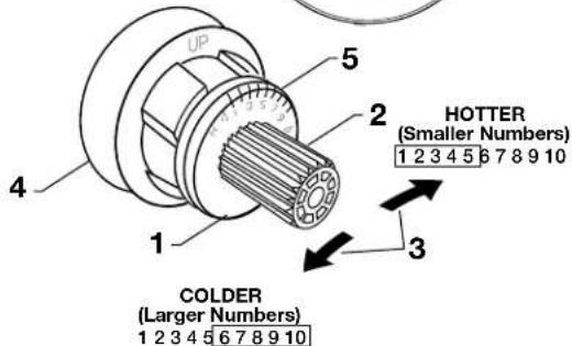
text_image
UP 5 2 HOTTER (Smaller Numbers) 1 2 3 4 5 6 7 8 9 10 1 3 COLDER (Larger Numbers) 1 2 3 4 5 6 7 8 9 10- RemoveCARTRIDGE(B) as detailed in steps above.
- Remove PIN (A) from CARTRIDGE (B) by pulling.
- Separate MANIFOLD (C) from CARTRIDGE (B) by pulling.
- Rotate CARTRIDGE (B) 180 degrees and reinstall MANIFOLD (C) with PIN (A).
- The "UP" TEXT (D) should now be facing downward during installation of the CARTRIDGE (B).
Standard
Back to Back

BACK TO BACK INSTALLATION
DIVERTER TYPE FUNCTION
2-way discreet

2-way shared
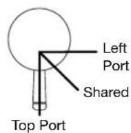
3-way shared
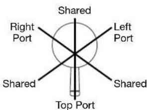
text_image
Shared Right Port Left Port Shared Shared Top Port3-way discreet
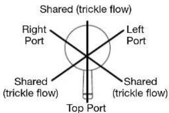
text_image
Shared (trickle flow) Right Port Left Port Shared (trickle flow) Shared (trickle flow) Top Port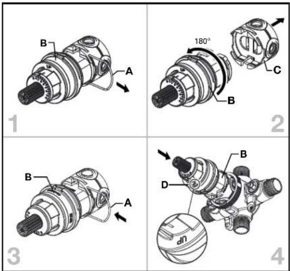
For toll-free information and answers to your questions, call: 1 (800) 442-1902
Mon. - Fri. 8:00 a.m. to 8:00 p.m. EST
Saturday 10:00 a.m. to 4:00 p.m. EST
IN CANADA 1-800-387-0369
(TORONTO 1-905-306-1093)
Weekdays 8:00 a.m. to 7:00 p.m. EST IN MEXICO 01-800-839-1200

PART OF LIXIL
INSTRUCTIONS D'INSTALLATION
TU064740

natural_image
Technical line drawing of a mechanical flange assembly with bolted components (no text or symbols)text_image
Technical diagram of a mechanical assembly with numbered components and labeled parts2 INSTALLATION DU MÉCANISME SUR UN MUR FIN
text_image
Technical diagram of a mechanical assembly with numbered components and cross-sectional views3 INSTALLATION DES MANETTES
text_image
Technical diagram of a mechanical assembly with numbered components, likely a pump or motor component.UN SERVICE
MISE EN GARDE
natural_image
Technical line drawing of a mechanical flange assembly with bolted components (no text or symbols)text_image
Ø 7-7/8" (200 mm) H Ctext_image
Technical diagram of a mechanical assembly with numbered components and labeled partstext_image
Technical diagram of a mechanical assembly with numbered components, likely a valve or pump component.SERVICIO
PRECAUCIÓN
Lunes a Viernes 8:00 a.m. a 6:00 p.m.
Sabado 10:00 a.m. a 4:00 p.m.