
H-10468 - Jack Uline - Free user manual and instructions
Find the device manual for free H-10468 Uline in PDF.

User questions about H-10468 Uline
0 question about this device. Answer the ones you know or ask your own.
Ask a new question about this device
Download the instructions for your Jack in PDF format for free! Find your manual H-10468 - Uline and take your electronic device back in hand. On this page are published all the documents necessary for the use of your device. H-10468 by Uline.
USER MANUAL H-10468 Uline
ULINE H-10467, H-10468 HYDRAULIC FLOOR JACK
1-800-295-5510 uline.com
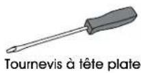
TOOL NEEDED
Flathead
Screwdriver
natural_image
Line drawing of a manual hand truck with a long handle and side wheels (no text or symbols)SAFETY
• Study, understand and follow all instructions before operating this device.
- Do not exceed rated capacity.
- Inspect the jack before each use. Do not use jack if damaged, altered, modified, in poor condition, leaking hydraulic fluid or unstable due to loose or missing components.
- Use only on hard, level surfaces with less than 3 degrees of slope.
- This is a lifting device only. Immediately after lifting, support load with jack stands.
• Center load on saddle prior to lifting.
- Do not move or dolly with jack loaded.
- Use wheel chocks on opposing wheels before jacking a vehicle.
- Do not get under a vehicle until it is fully supported by jack stands.
- Do not use any materials that may serve as risers, spacers or extenders between the lifting saddle and the load.
- Do not use any adapters that replace the stock lifting saddle unless approved or supplied by the jack manufacturer.
- Do not use with lawn mowers or lawn tractors.
- Do not use or modify this product for any other purpose than for what it was designed.
• Always lower the jack slowly and carefully. - Failure to heed these warnings may result in fatal personal injury, property damage or both.
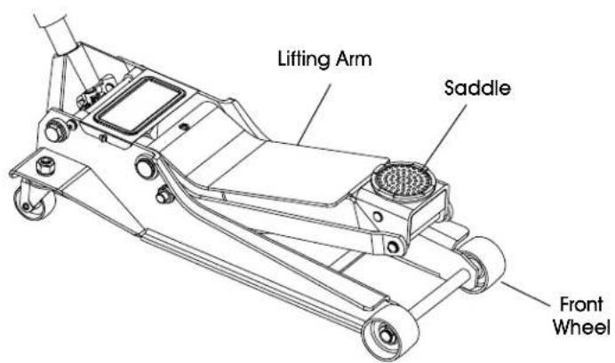
PARTS
text_image
Lifting Arm Saddle Front Wheel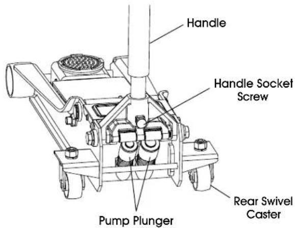
text_image
Handle Handle Socket Screw Pump Plunger Rear Swivel CasterASSEMBLY
BEFORE FIRST USE
- Carefully remove the retaining clip attached to the handle socket. (See Figure 1)

CAUTION! The socket will tend to spring upward when the clip is removed. To prevent possible injury, place one hand on top of the handle socket to control the upward motion of the handle socket retaining clip, then carefully remove the retaining clip. After removing, slowly allow the handle socket to rise back into the resting position.
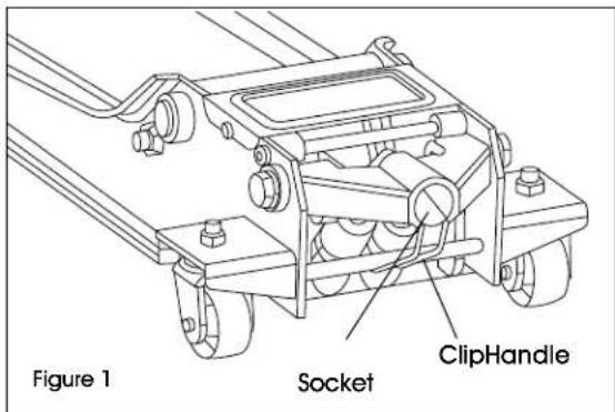
text_image
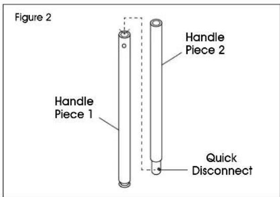
Figure 1 Socket ClipHandle- Press the quick disconnect button on handle piece 2 and insert into handle piece 1. The quick disconnect will automatically pop out when the hole position is aligned with the quick disconnect button. (See Figure 2)
text_image
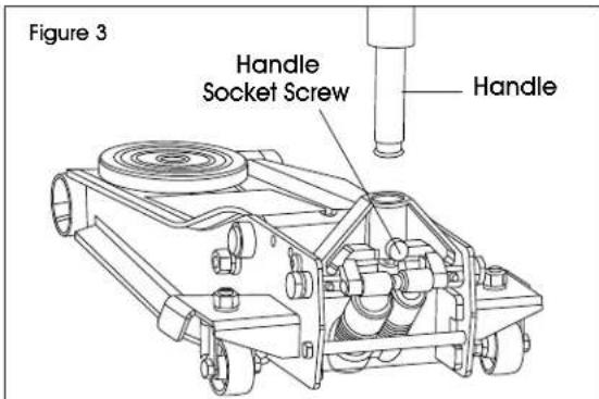
Figure 2 Handle Piece 1 Handle Piece 2 Quick Disconnect- Loosen the handle socket screw to insert the assembled handle. (See Figure 3)
text_image
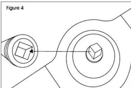
Figure 3 Handle Socket Screw Handle- Place handle into handle socket. Align the square hole located at the bottom of the handle over the square bolt inside the handle socket. (See Figure 4)
natural_image
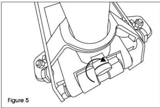
Technical diagram showing two 3D geometric shapes with concentric circles and a labeled figure 'Figure 4' (no text or symbols on the shapes themselves)- Secure the handle in place by tightening the handle socket screw. (See Figure 5)
natural_image
Technical line drawing of a mechanical assembly with a rotating component (no text or symbols)ASSEMBLY CONTINUED
AIR PURGE PROCEDURE

IMPORTANT! Before first use, perform the following air purge procedure to remove any air that may have been added into the hydraulic system due to product shipment and handling. Complete this step without any weight on the jack.
- Remove the cover plate by unfastening the screws. (See Figure 6)
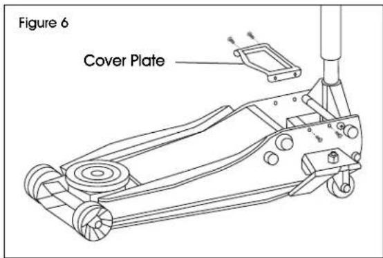
text_image
Figure 6 Cover Plate- Using handle, turn the release valve counterclockwise one full turn to the open position. (See Figure 7)
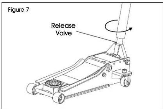
text_image
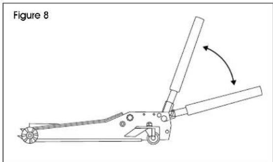
Figure 7 Release Valve- Rapidly pump the handle 6-8 times. Leave the handle in the down position to expose the oil fill plug. (See Figure 8)
natural_image
Technical line drawing of a mechanical tool or device with an arrow indicating rotation (no text or symbols present)- With a flathead screwdriver, push the oil fill plug slightly to the side to purge trapped air from the system. Ensure oil fill plug is securely in place after purging trapped air. (See Figure 9)
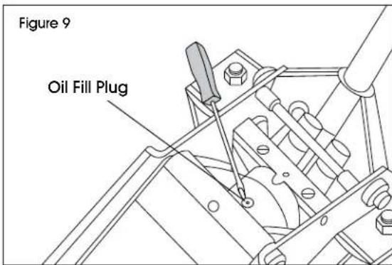
text_image
Figure 9 Oil Fill Plug- Replace the cover plate by fastening the screws (See Figure 10)
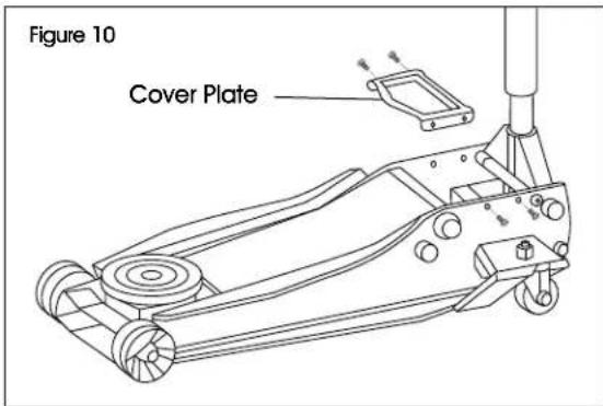
text_image
Figure 10 Cover Plate- Using handle, turn the release valve clockwise to the closed position. (See Figure 11)

text_image
Figure 11 Release Valve- The jack is now ready for use. Check for proper pump action.
OPERATION
RAISING THE JACK
- Chock the vehicle's wheels for lifting stability. Secure the load to prevent inadvertent shifting and movement.
- Set the parking brake in the vehicle.
- Refer to the vehicle manufacturer owner's manual to locate approved lifting points on the vehicle. Position the jack so the saddle is centered and will contact the load lifting point firmly.
- Close the release valve by turning handle clockwise until it is firmly closed.
- Before raising the vehicle, double check and verify the saddle is centered and has complete contact with the lifting point.
- Pump the handle to lift the jack until the saddle contacts the load. Pump the jack handle to lift the vehicle to the desired height. After lifting, support the load with appropriately rated vehicle jack stands before working on the vehicle. (See Figure 12)
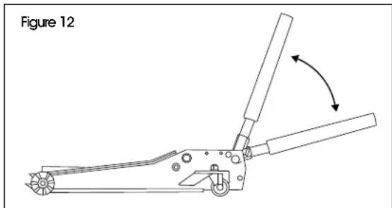
natural_image
Technical line drawing of a mechanical tool or clamp device with directional arrows indicating movement (no text or symbols)
WARNING! Never wire clamp or otherwise disable the lift control valve to function by any means other than using the operator's hand. Use the handle supplied with this jack or an authorized replacement handle to ensure proper release valve operation. Do not use extensions on the operating handle.
LOWERING THE JACK

WARNING! Use extreme caution when lowering the jack. The jack handle may turn rapidly. Opening the release valve too fast can cause the jack to lower rapidly. Failure to heed these warnings could cause serious injury or death.
- Raise the load enough to allow clearance for the jack stands to be removed, then carefully remove the jack stands.
- Grasp the handle firmly with both hands. Securely hold on to the jack handle so user's hands do not slip. Ensure the release valve does not rapidly lower.
- Carefully open the release valve by slowly turning the handle counterclockwise. Do not allow bystanders around the jack or under the load when lowering the jack. (See Figure 13)
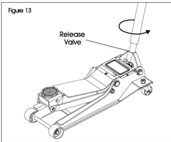
text_image
Figure 13 Release Valve- After removing the jack from under the load, keep the jack in the lowered position to reduce exposure to rust and contamination.
MAINTENANCE
Follow the maintenance instructions carefully to keep equipment in good working condition. Never perform any maintenance while it is under a load.
INSPECTION
Inspect the product for damage, wear and broken or missing parts. Ensure all components function before each use. Follow lubrication and storage instructions for optimum product performance.
BINDING
If the product binds while under a load, use equipment with equal or larger load capacity to lower the load safely to the ground. After unbinding, clean, lubricate and test that equipment works properly. Rusty components, dirt or worn parts can be causes of binding. Clean and lubricate the equipment as indicated in the lubrication section. Test the equipment by lifting it without a load.
CLEANING
If the moving parts of the equipment are obstructed, use cleaning solvent or another good degreaser to clean the equipment. Remove any existing rust with a penetrating lubricant.
LUBRICATION
This equipment will not operate safely without proper lubrication. Using the equipment without proper lubrication will result in poor performance and damage to the equipment. Some parts of this equipment are not self-lubricating. Inspect the equipment before each use and lubricate when necessary. After cleaning equipment, use a light penetrating oil lubricating spray.
- Use a good lubricant on all moving parts.
• For light duty use: lubricate monthly. - For heavy and constant use: lubricate weekly.
- Never use sandpaper or abrasive material on the surfaces.

WARNING!
- Do not use motor oil in the jack. Only use a good grade anti-foaming hydraulic jack oil.
- Do not use hydraulic brake fluid, alcohol, glycerine, detergent, motor oil or dirty oil.
- Use of a non-recommended fluid can cause damage to a jack.
- Dispose of hydraulic fluid in accordance with local regulations.
ADDING OR REPLACING JACK OIL
- Position the jack on level ground and lower the saddle.
- Open release valve by turning handle counterclockwise.
- Remove the cover plate by unfastening the screws. (See Figure 14)

text_image
Figure 14 Cover Plate- Remove the oil plug. (See Figure 15)
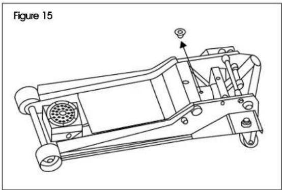
natural_image
Technical line drawing of a mechanical device with no visible text or symbols- If removing oil, turn the jack on its side to drain old oil from the oil fill hole. If not removing oil, proceed to the next step. (See Figure 16)

text_image
Figure 16MAINTENANCE CONTINUED
- Use a funnel to fill the oil case until oil level is just beneath the lower rim. Keep dirt and other foreign materials clear when pouring. (See Figure 17)
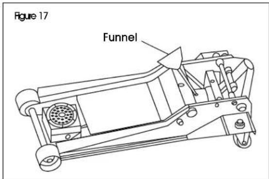
text_image
Figure 17 Funnel- Replace oil plug. (See Figure 18)
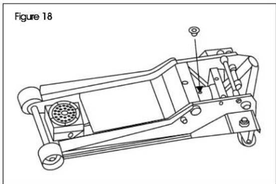
natural_image
Technical line drawing of a mechanical device with labeled components (no text or symbols beyond label)- Replace cover plate by fastening the screws and perform the air purge procedure. (See Figure 19)
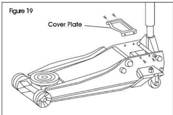
text_image
Figure 19 Cover PlateRUST PREVENTION
- Check rams and pump plungers on the hydraulic unit assemblies daily for any signs of rust or corrosion.
- Without a load, lift the equipment as high as it goes and look under and behind the lifting points. If signs of rust are visible, clean as needed.
STORING THE JACK
- Lower the lifting arm.
- Place the handle in the upright position.
- Store in a dry location, recommended indoors.

NOTE: If the jack is stored outdoors, be sure to lubricate all parts before and after use to ensure the jack stays in good working condition. Always store jack in the fully retracted position when stored in outdoor or caustic environments that can cause corrosion and/or rust.
TROUBLESHOOTING
| OPERATING ISSUE CAUSES RECOMMENDATIONS | ||
| Jack will not lift load. Release | valve is not completely closed.Weight capacity exceeded.Air is in the hydraulics.Low oil level.Hydraulic unit malfunctioning. | Turn handle clockwise.Lighten load.Purge air from system.Add oil as required.Replace the unit. |
| Jack will not hold load. Release | valve is not completely closed.Low oil level.Hydraulic unit malfunctioning. | Turn handle clockwise.Add oil as required.Replace the unit. |
| Jack will not lower. Oil reservoir | is overfilled.Jack is binding or foreign obstruction. | Drain excess oil. Lubricate moving parts.Remove obstruction. |
| Poor jack lifting. Release valve | is not completely closed.Air is in the hydraulics.Low oil level.Hydraulic unit malfunctioning. | Turn handle clockwise.Purge air from system.Add oil as required.Replace the unit. |
| Will not lift to full extension. Low oil level. Add oil as required. | ||
Safe operating temperature is between 40°F – 105°F.
ULINE H-10467, H-10468 GATO HIDRÁULICO DE PISO
800-295-5510 uline.mx
natural_image
Line drawing of a manual push truck with handle and wheels (no text or symbols)SEGURIDAD
natural_image
Technical line drawing of a mechanical assembly with no visible text or symbolsnatural_image
Line drawing of a manual hand truck with a long handle and wheels (no text or symbols)OUTIL REQUIS
SÉCURITÉ
natural_image
Technical diagram showing two circular components with a central hexagonal bolt, connected by a line to concentric rings (no text or symbols)natural_image
Technical line drawing of a mechanical assembly with rotational motion indicator (no text or symbols)MONTAGE SUITE
PROCÉDURE DE PURGE DE L'AIR

text_image
Figure 6 Plaque-couverclenatural_image
Line drawing of a manual tool with a handle and lever mechanism, labeled Figure 8 (no text or symbols on the diagram itself)text_image
Figure 10 Plaque-couverclenatural_image
Technical line drawing of a mechanical device with a lever mechanism and directional arrow (no text or symbols)


