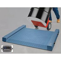
H-11934 - Scale Uline - Free user manual and instructions
Find the device manual for free H-11934 Uline in PDF.


User questions about H-11934 Uline
0 question about this device. Answer the ones you know or ask your own.
Ask a new question about this device
Download the instructions for your Scale in PDF format for free! Find your manual H-11934 - Uline and take your electronic device back in hand. On this page are published all the documents necessary for the use of your device. H-11934 by Uline.
USER MANUAL H-11934 Uline
ULINE H-11933, H-11934 PORTABLE FLOOR SCALE
1-800-295-5510
uline.com
TOOLS NEEDED
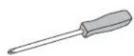
Phillips
Screwdriver
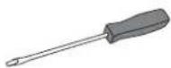
Flathead
Screwdriver

Two Person Assembly Recommended
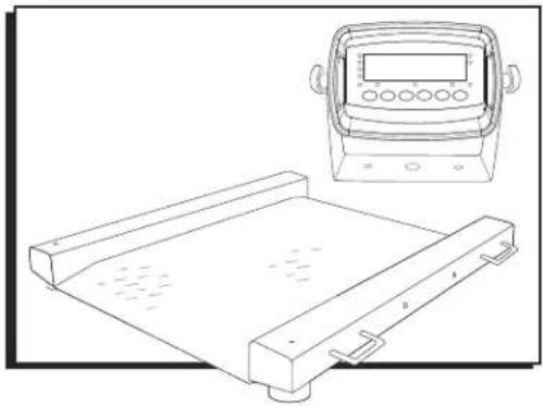
natural_image
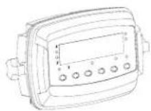
Line drawing of a balance scale with an inset display unit (no text or symbols)PARTS
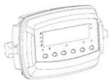
Indicator x 1
natural_image
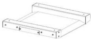
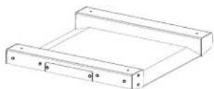
Technical line drawing of a mechanical bracket or frame (no text or symbols)Portable Floor Scale x 1
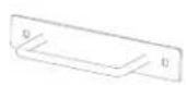
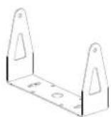
Handle x 2 Foot x 4

natural_image
Pure electrical circuit lines without any symbols
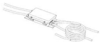
Installation Guide x 1Junction Box and Cable x 1U-Fram
SAFETY

Read and follow all instructions before use. Calibration, inspections and maintenance should be performed by professionals.
- Ensure the indicator rests on a stable surface.
- Do not disassemble or modify unit.
- Do not exceed the rated load limit of the unit.
- Do not step on the unit.
- Do not jump on the unit.
- Do not use this product if there are any signs of damage.
- Do not use for purposes other than weighing.
- Avoid faulty readings before weighing samples with static electric charge by discharging them or wiping the indicator with an anti-static agent.
ELECTRICAL SAFETY
- Unit must be connected to a GFCI outlet.
- Disconnect power before servicing unit.
- All operators must discharge themselves before servicing unit by touching a grounded surface or by wearing a grounded anti-static wrist strap.
- Always pull the plug – not the cord – when disconnecting from the outlet.
- Do not use if the power cord is worn or damaged.
- Power cords should only be replaced by qualified service technicians using genuine replacement parts.
SETUP
PREPARATION
- If the indicator is powered by an adapter, plug the adapter directly into the "DC" pin located at the bottom of the indicator.
• Always use a wall outlet to avoid interference from other wires. - Turn on the indicator when there is no load.
-
Calibrate before weighing when the scale is initially installed or moved to a new location.
-
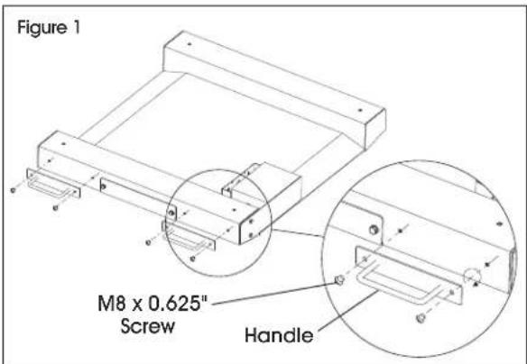
Install the two handles using four M8 x 0.625" screws with a Phillips screwdriver. (See Figure 1)
text_image
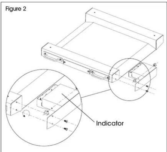
Figure 1 M8 x 0.625" Screw Handle- Remove the indicator. (See Figure 2)
text_image
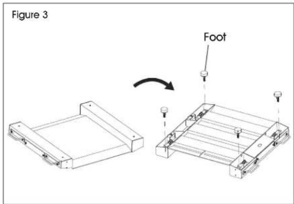
Figure 2 Indicator- With a second person, flip the scale upside down. Screw in the feet clockwise on the four corners. Ensure feet are level. (See Figure 3)
text_image
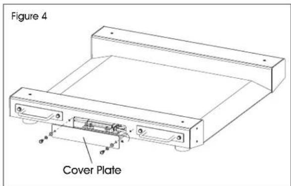
Figure 3 Foot- Remove the side cover plate. (See Figure 4)
text_image
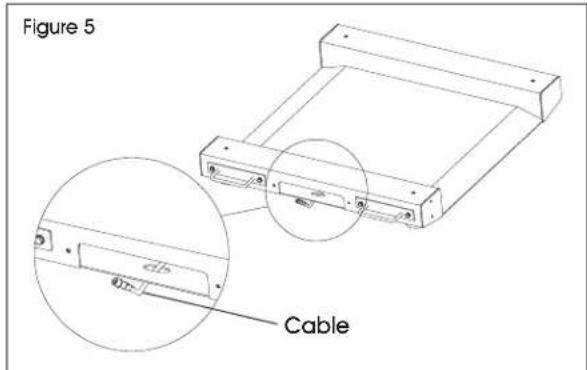
Figure 4 Cover Plate- Run the cable through the oval hole inside the cavity and pull it out from the bottom. (See Figure 5)
text_image
Figure 5 CableSETUP CONTINUED
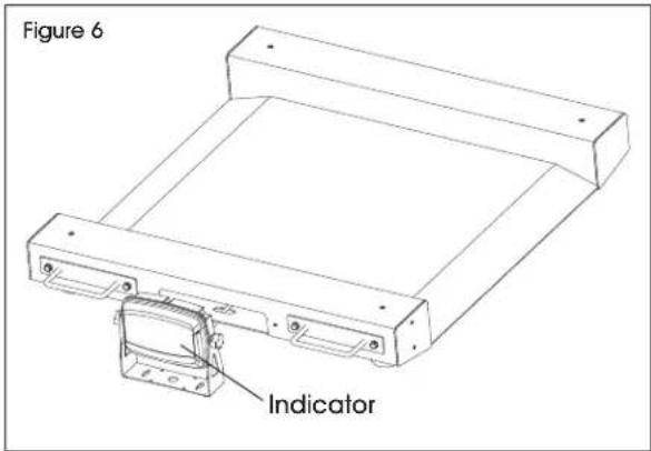
- Plug the cable to the load cell port on the indicator. (See Figure 6)
text_image
Figure 6 Indicator- Resecure the cover plate. (See Figure 7)
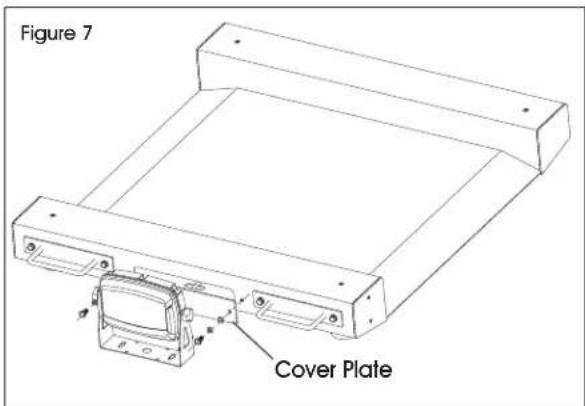
text_image
Figure 7 Cover Plate- If the scale is not level, adjust the feet from the top with a flathead screwdriver. (See Figure 8)
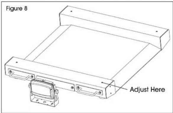
text_image
Figure 8 Adjust Here
IMPORTANT! Before measuring your weight, ensure scale is placed horizontally on a hard and flat surface. Avoid placing it on soft wooden floors, carpets or gaps between tiles and avoid bringing it into contact with the wall or other objects.
POWER SUPPLY
AC ADAPTER
- If the indicator is powered by an adapter, plug the adapter directly into the "DC" pin located at the bottom of the indicator. It is recommended to plug into a wall outlet to avoid interference with other wirings.
BATTERY
- If you have an indicator with the rechargeable battery option, charge the internal battery fully before first use.
- A 110 to 220 V AC adapter should be provided with the indicator. Use only the AC adapter provided to prevent damage to the indicator. To keep the battery in best condition, fully discharge the battery every month by leaving the indicator on until the indicator powers off, and then recharge fully. If the battery is not going to be used for a long period of time, it is recommended to remove it to avoid leakage.
OVERVIEW OF CONTROLS
CONTROL PANEL
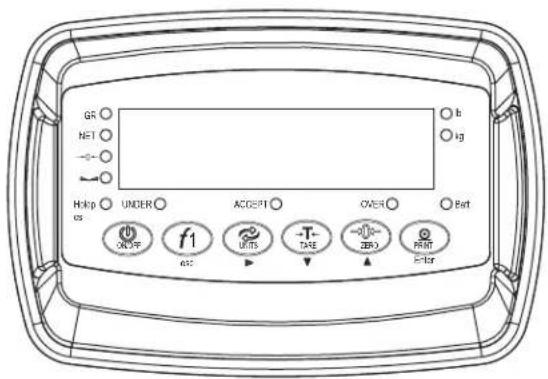
text_image
GR NET - - - Help OS UNDER ACCEPT OVER Bet OK f1 Units -T- DATE 2003 PRINT EnterDISPLAY
| LED INSTRUCTION | |
| GR ON when the current weight is GROSS weight. | |
| NET ON when the current weight is NET weight. | |
| →0← | ON when the current weight is 0 lb. |
| The weighing data is stable. | |
| Hold ON when the weight is hold. | |
| UNDER ON when the weight below min. value. | |
| ACCEPT ON when in normal weight. | |
| OVER ON when overload. | |
| Batt | GREEN when the battery is full.RED when it is low. |
| lb. ON when the weight unit is pound. | |
| kg. ON when the weight unit is kilogram. | |
| g ON when the weight unit is gram. | |
| OZ. ON when the weight unit is ounce. | |
CONTROL FUNCTIONS
| KEY PRIMARY FUNCTION SECONDARY FUNCTION | ||
 | ON/OFPowers the indicator ON or OFF if held for two seconds. | ---- |
 esc esc | F1Used as the main function key for either hold or piece counting application. | ESCSaves and exits. |
 | UNITSShifts between weighing units. Right arrow key. | ▶ |
 | TAREResets the scale to zero when there is something on the scale.(ex. Tare out the weight of a pallet to weigh only the product on it.) | ▼Down arrow key. |
 | ZEROZeros the scale. | ▲Up arrow key. |
 Enter Enter | PRINTPrints data. | ENTEREnter. |
OVERVIEW OF CONTROLS CONTINUED
REAR PANEL
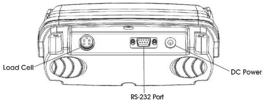
text_image
Load Cell RS-232 Port DC Power| PORT FUNCTION | |
| LOAD CELL Port for connecting load cell. | |
| RS-232 PORT Serial interface port (computer, printer). | |
| DC POWER Port for DC power (DC 12 V adapter is available). |
OPERATION
POWER ON
Turn on the power by pressing the power button for two seconds. Once on, the scale will ask the voltage and then begin to auto-check and count down from 9-0 sequentially before entering the weighing mode.

NOTE: Anything on the scale before powering on will automatically be tared out.
ZEROING
The zero function is used only when the scale is empty and is not at gross zero due to material buildup.
- Pressing the ZERO key will reset scale to 0.
- Depending on what the manual zero range parameter is set to, you can zero out any number within the set selection. After that, you will receive an error and will need to take out the weight.
UNIT SELECTION
To switch between measuring units (kg./g./lb./oz.), press the UNITS key.
TARE FUNCTION
The tare function is used when you only want to see the current change in weight, not the entire amount of weight that is on the scale.
- When the indicator is in gross mode (gross light is shown), pressing the TARE key will tare the current weight on the scale and enter the net mode (net light shown). For example, if using a container, add the container to the scale, press TARE and the display will show the tare symbol and reset back to 0.
- Add product to the scale to weigh without the weight of the container.
- To exit tare mode, press the TARE key again to enter gross mode and you will see the total weight of the container and the product.

NOTE: If removing the container, the scale will show the negative weight of the container.
OPERATION CONTINUED

NOTE: F1/ESC is pre-set to "HOLD" function. To switch to "COUNT", go to parameter setting C50 and select 2.
HOLD
There are three different hold functions to choose from in the C11 parameter.
PEAK HOLD
Grabs the highest weight (for materials testing, ie. tension and pulling force).
- Press the F1/ESC key, then add weight to the scale.
- The indicator will show the highest weight it recorded and hold it on the screen until a higher weight is placed on the scale.
MANUAL HOLD
Grabs the current weight and holds it so it will not change or fluctuate.
- While weighing, press F1/ESC and the indicator will hold the current weight on the screen until F1/ESC is pressed again.
AVERAGE HOLD
Used for weighing an animal. The indicator will display the average weight sampled from three seconds.
- Add livestock to scale and press F1/ESC.
- Indicator screen will show LOC for three seconds, then display the average weight from those three seconds.
- Press F1/ESC again to exit holding mode.
COUNTING FUNCTION
The counting function is used to count a high volume of identical parts. Set a sample and then either add to the sample or take away from the sample to count the number of objects on the scale.
- In weighing mode, put a sample weight on the scale. (Sample options are 5, 10, 20, 50, 100, 200, 500.)
- Press the F1/ESC key to go to the counting mode ("pcs" will light up).
- It will then display the sample number (ex. PCS 0), which you can change using the up or down arrows.
- Press the PRINT/ENTER key to confirm the sample number.
- The scale is now ready to start counting. Load item on the scale and the indicator will show the quantity.
- To exit counting mode, press the F1/ESC key.
- If you want to count a different product, hold the F1/ESC key and the sample pieces will reset back to zero.
If the indicator is connected to a printer and the weight on the scale is stable, press the PRINT/ENTER key to print the current weight.
CALIBRATION
HOW TO ENTER
- Turn on the scale by holding ON/OFF for two seconds.
- Press F1/ESC and PRINT/ENTER together to access the setup menu.
Available Keys:
| KEY KEY NAME KEY FUNCTION | ||
| RIGHT ARROW | Move to the right by one place of the set value. | |
| UP ARROW Increase the set value. | ||
| DOWN ARROW Reduce the set value. | ||
| esc | ESC | Exit current menu. |
| enter | ENTER | Move into next menu. |
OPERATION CONTINUED
CALIBRATION MENU
- Turn on the scale by holding ON/OFF for two seconds.
- Press F1/ESC and PRINT/ENTER together to access the setup menu.
- If done correctly, the display should now show COI.
- Press PRINT/ENTER to access the C1 channel. The display should show C1 #
- Press ZERO to choose which unit you want to calibrate in (1 = kg., 2 = lb.).
- Press PRINT/ENTER to set the value. The display will now show CO3.
- Press PRINT/ENTER to access the C2 channel. The display should show C2 #
- Press ZERO ▲ to change the setting to the decimal places desired. (The C2 channel is used to adjust the decimal point on the scale. A value of 1 means there is one digit behind the decimal point.)
- Press PRINT/ENTER to set the value. The display will now show CO3.
- Press PRINT/ENTER to access the C3 channel. The display should show C3 #
- Press ZERO to cycle through the values until the desired graduation appears. (The C3 channel adjusts the divisions on the scale. A value of 1 selected and C2 set to 1 means the scale will read in 0.1 lb. increments.)
- Press PRINT/ENTER to set the value. The display will now show CO4.
- Press PRINT/ENTER to access the C4 channel. The display will show # # # # # #
- Enter in the maximum capacity you want to use for this scale by using UNITS to move the cursor right, and TARE ▼ and ZERO ▲ to move the values down and up. (The C4 channel is to move the used to enter in the max capacity of the scale. Ensure this does not exceed the maximum capacity of the scale. Maximum capacity divided by the increment set in C02 and C03 above cannot exceed 5,000.)
- Press PRINT/ENTER to set the value. The display will now show COS.
- Press PRINT/ENTER to access the C5 channel. The display should show CS #
-
The C5 channel calibrates zero on the scale. Ensure the scale is empty.
-
Press ZERO ▲ to change the value to 1.
- Press PRINT ENTER. This display will count down from 10-1 while the scale is calibrating zero. When the display shows zero, the zero calibration is complete.

NOTE: The portable floor scale offers two calibration methods: Single Point, which uses one weight to calibrate, or Linear Calibration, which uses multiple (2-7) weights for a more accurate calibration.
SINGLE POINT CALBIRATION
- Press PRINT ENTER to continue. The display will now show COS.
- Press PRINT ENTER to access the C06 channel. The display will show C6 0.
- The C6 channel is used to calibrate the scale with a known weight. Press ZERO. The display will flash to set the value of C6 to C61. Press PRINT/ENTER. The display will flash SPAN, and then show # # # # # #.
- Enter the calibration weight value you will use (at least 10% of max capacity you set in C04) by using UNITS ▶ to move the cursor right, and TARE ▼ and ZERO ▲ to move the values down and up.
- Place the calibration weight on the empty scale and press PRINT/ENTER.
- The scale will count down from 10 to 0. Once 0 has been reached, the display will show CALEnO.
- Press PRINT ENTER to set the value. The display will now show CO7.
- Press F1/ESC to save and exit the setup menu.
- The scale has now been calibrated. The display will show the value of the calibration weight on the scale.
- If the scale does not show the value of the calibration weight, check that the feet on the platform are not screwed in too tightly, and verify that the platform is level.
- Unload the scale; the display should read 000000.
- If the scale does not display 000000, check that the feet on the platform are not screwed in too tightly, and verify that the platform is level.
OPERATION CONTINUED
LINEAR CALIBRATION
- Press PRINT/ENTER to continue. The display will now show C06.
- Press PRINT/ENTER to access the C06 channel. The display will show C5 0.
- The C6 channel is used to calibrate the scale with a known weight. Press ZERO to set the value of C6 to C6 2. Press PRINT/ENTER. The display will flash SPAN and then show LnE 2.
- Press ZERO ▲ to enter the number of weights you want to use (2-7); the more you use, the more accurate the calibration will be. (An example of 2 will be used.)
- Press PRINT/ENTER to set the value. The screen will flash dbno01 then 000100.
- Enter the lowest calibration weight value you will use (at least 10% of max capacity you set in C04) by using UNITS ▶ to move the cursor right and TARE ▼ and ZERO ▲ move the values down and up.
- Place the calibration weight you have on the empty scale and press PRINT/ENTER.
- The scale will count down from 10 to 0. Once 0 has been reached, the display will show the screen will flash dbno01 then 000100.
- Enter the next calibration weight value you will use by using UNITS ▶ to move the cursor right, and TARE ▲ and ZERO ▼ to move the values down and up.
- Place the calibration weight you have on the empty scale and press PRINT/ENTER.
- The scale will count down from 10 to 0. Once 0 has been reached, the display will show CALEnO.
- Follow steps 7-12 on the single point calibration instructions.
INDICATOR PARAMETER SETTINGS
The parameter settings menu has a calibration section (C01 to C07 explained above) and a parameter settings section (C08 and up).
To access the calibration section, the seal switch (located at one corner of the PCB) must be off. This will allow access to all C01 and up settings. If the seal switch is on, then only C08 and up can be accessed by the user. If you break the official seal by opening the back of the indicator to access the seal switch, you may need to have the indicator recertified. Adjust the seal switch back to the original setting after calibration/configuration has been performed.
To enter calibration/parameter settings, follow the procedure below.
- Ensure UNITS is set to either kg or lb.
- Press and hold F1/ESC and PRINT/ENTER keys at the same time for two seconds.
- Navigate through the settings (C01 to C45) as shown in the table on page 9 by using the arrow keys and return keys as labeled under each indicator button.
- Press PRINT key to enter/edit the parameter setting.
- Press PRINT/ENTER or F1/ESC keys to save and exit settings at any time.
OPERATION CONTINUED
PARAMETER SETTINGS
| FUNCTION PARAMETER SETTINGS/OPTIONS | ||
| Weighing Unit C01 | 1 = kg.2 = lb.3 = gram4 = oz.NOTE: For calibration, only kg. or lb. are allowed. | |
| Decimal Setting C02 | 0 = no decimal1 = 0.02 = 0.003 = 0.0004 = 0.0000 | |
| Graduation Setting (readability of the least significant digit) | C03 | Options: 1, 2, 4, 10, 20, 50Example with no decimal places (ie. C02=0)1 = 1 lb.2 = 2 lb.5 = 5 lb.10 = 10 lb.20 = 20 lb.50 = 50 lb. |
| Maximum Capacity C04 Set max capacity (ex. 100 kg. = 0100.00) | ||
| Zero Calibration C05 | 0 = Zero calibration not needed.1 = Set the zero calibration.NOTE: Ensure scale is empty and the stable light is on. | |
| Calibration C06 | 0 = Calibration not needed.1 = Ready to calibrate with one calibration weight.2 = Ready to calibrate using multiple calibration weights (linear).3 = Sensitivity output. | |
| Restore Default Settings C07 | 0 = Do not restore.1 = Restore to default settings. | |
| Warning Tone C08 | 0 = Turn off warning tone.1 = Turn on warning tone. | |
| Automatic Power-Off | C09 | 0 = Turn off auto power-off.10 = Power off automatically if no change within 10 minutes.30 = Power off automatically if no change within 30 minutes.60 = Power off automatically if no change within 60 minutes. |
| Power Saving Mode | C10 | 0 = Turn off power saving setting.3 = Turn off display if no change within three minutes.5 = Turn off display if no change within five minutes. |
OPERATION CONTINUED
| FUNCTION PARAMETER SETTINGS/OPTIONS | ||
| Hold Function C11 | 0 = Turn off hold function.1 = Peak hold: Grabs the highest weight.2 = Manual hold: Grabs the current weight.5 = Auto average hold: Average hold without the need to press the hold key. | |
| Unit Conversion | C12 | * See Unit Conversion Parameter Settings table on page 12. |
| Upper Limit Alarm | C13 | Set upper limit within the max. capacity. |
| Lower Limit Alarm | C14 | Set lower limit within the max. capacity. |
| Inner Code Display C15 Check the inner code (raw data). | ||
| Set Date C16 Set date from left to right: year/month/day. | ||
| Set Time | C17 | Set the time from left to right: hour/minute/second. |
| Communication Setting | C18 | Set the time from left to right: hour/minute/secondSet the serial interface data output method:0 = Turn off serial interface data output.1 = Continuous sending mode, for remote display.2 = Print to paper thermal ticket printer.3 = Command request mode, for computer.4 = PC continuous sending mode, for computer.5 = PC/remote display, continuous sending mode.6 = Print to adhesive label thermal printer.7 = Print to Zebra/large adhesive label thermal printer.8 = Reserved. |
| Baud Rate | C19 | 0 = 1,2001 = 2,4002 = 4,8003 = 9,6004 = 14,400 |
| Manual Zero Range | C20 | 0 = Turn off manually zero setting.1 = +/- 1% max capacity2 = +/- 2% max capacity4 = +/- 4% max capacity10 = +/- 10% max capacity20 = +/- 20% max capacity100 = +/- 100% max capacity |
OPERATION CONTINUED
| FUNCTION PARAMETER SETTINGS/OPTIONS | ||
| Initial Zero Range C21 | 0 = No initial zero setting.1 = +/- 1% max capacity2 = +/- 2% max capacity4 = +/- 4% max capacity10 = +/- 10% max capacity20 = +/- 20% max capacity100 = +/- 100% max capacity | |
| Zero Tracking C22 | 0 = Turn off zero tracking.0.5 = +/- 0.5d1.0 = +/- 1.0d2.0 = +/- 2.0d3.0 = +/- 3.0d4.0 = +/- 4.0d5.0 = +/- 5.0dNOTE: Zero tracking range cannot be bigger than manual zero range.NOTE: d = division. | |
| Zero Tracking Time C23 | 0 = Turn off zero tracking time.1 = 1 second2 = 2 seconds3 = 3 seconds | |
| Overload Range C24 | 00 = Turn off overload range.01-99d = Overload range setting. | |
| Negative Display C25 | 0 = -9d10 = -10% max. capacity20 = -20% max. capacity50 = -50% max. capacity100 = -100% max. capacity | |
| Standstill Time C26 | 0 = Quick1 = Medium2 = Slow | |
| Standstill Range C27 | 1 = 1d2 = 2d5 = 5d10 = 10d | |
| Digital Filter(for filtering moving weight such as animals) | C28 | 0 = Turn off dynamic filter.1 = 1 digital filter strength2 = 2 digital filter strength3 = 3 digital filter strength4 = 4 digital filter strength5 = 5 digital filter strength6 = 6 digital filter strengthNOTE: The higher the number, the higher the filter strength. |
| Noise Filter C29 | 0 = Turn off noise filter.1 = 1 digital filter strength2 = 2 digital filter strength3 = 3 digital filter strength | |
OPERATION CONTINUED
| FUNCTION PARAMETER SETTINGS/OPTIONS | ||
| Print Time and Date C30 | 0 = yy.mm.dd1 = mm.dd.yy2 = dd.mm.yy3 = yy.mm.dd | |
| Zero Setting C34 | 0 = Back to zero.1 = Press ZERO and PRINT together to go back to zero. | |
| Gravity of Calibration Location C36 9.7000 - 9.9999 | ||
| Gravity of Destination C37 9.7000 - 9.9999 | ||
| Version No. C38 ---- | ||
| Weight Reversed Setting C39 | 0 = Normal Weight.1 = Weight Reversed. | |
| Print Mode | C41 | 0 = Auto mode1 = Gross mode2 = Tare mode |
| Print Carriage Return | C42 | 0-9 (How much space between printouts.) |
| Space Print | C43 | 0-9 (Where the data prints on the paper: 0 = left; 9 = right) |
| Date Print | C44 | 0 = Do not print the date.1 = Print the date. |
| Time Print | C45 | 0 = Do not print the time.1 = Print the time. |
| Baud Rate for 2nd RS232 | C48 | 0 = 1,200 (for remote display)1 = 2,4002 = 4,8003 = 9,600 |
| F1 (hold or count) | C50 | 1. hold 2. count |
UNIT CONVERSION PARAMETER SETTINGS
| PARAMETER SETTINGS | UNITS AVAILABLE |
| C0 1 = 1 and C 12 = 0 | kg. |
| C0 1 = 2 and C 12 = 0 | lb. |
| C0 1 = 1 and C 12 = 1 | kg./lb. |
OPERATION CONTINUED
DEFAULT PARAMETER SETTINGS
| FUNCTION PARAMETER DEFAULT SETTING | ||
| Weighing Unit C01 1 | ||
| Decimal Setting C02 0 | ||
| Graduation Setting C03 1 | ||
| Maximum Capacity C04 100,000 | ||
| Zero Calibration C05 0 | ||
| Calibration C06 0 | ||
| Restore Default C07 0 | ||
| Warning Tone | C08 1 | |
| Automatic Power Off | C09 | 60 |
| Power Saving Mode | C10 | 0 |
| Hold Function | C11 | 0 |
| Unit Conversion | C12 | 1 |
| Upper Limit Alarm | C13 | 000000 |
| Lower Limit Alarm | C14 | 000000 |
| Inner Code Display | C15 | ---- |
| Set Date | C16 | ---- |
| Set Time | C17 | ---- |
| Communication Setting | C18 | 1 |
| Baud Rate | C19 | 3 (9,600) |
| Manual Zero Range C20 | 10 | |
| Initial Zero Range | C21 | 10 |
| Zero Tracking | C22 | 1.0 |
| Zero Tracking Time | C23 3 | |
| Overload Range | C24 9 | |
| Negative Display | C25 | 10 |
| Standstill Time | C26 1 | |
| Standstill Range | C27 2 | |
| Digital Filter | C28 3 | |
| Noise Filter | C29 2 | |
| Print Time and Date | C30 0 | |
OPERATION CONTINUED
| FUNCTION PARAMETER | DEFAULT SETTING | |
| Multi-Connection Add C34 0 | ||
| Gravity of Calibration Location C36 9.7936 | ||
| Gravity of Destination C37 9.7936 |
PRINT MODE
For printing on a non-adhesive ticket printer.
Parameters 16, 17, 30 and 42-45 all affect ticket print-out.
Normal Weighing Ticket Printout Example:
Date: 05/01/2017
Time: 11:30:52
Net: 25.6lb
Tare: 10.3lb
Gross: 35.9lb
Print to Adhesive Label Printers:
Format 1 Format 2
Date: 05/01/2017
Time: 11:30:52
Net: 25.6lb
Tare:
Gross: 10.3lb 35.9lb
Date: XX.XX. XX (yy.mm.dd)
Time: XX.XX.XX (hh.mm.ss)
NET 6.00kg (net weight)
TARE 2.88kg (tare)
GROSS 8.88kg (gross weight)
TROUBLESHOOTING
| ERROR CODE POSSIBLE CAUSES RECOMMENDATIONS | ||
| UUUUUU | Overload.Cables are not connected properly.Load cell is defective. | Reduce the weight.Check load cell connection.Inspect load cell. Check the input/output.If the above actions do not work, try the following instructions:Check if the cable that runs from the indicator to the junction box is damaged. If it is, replace the cable.Check for any water damage inside the junction box. If there is, replace the junction box.Ensure all wires on all five terminal blocks are not loose. Retighten the screws if needed.Recalibrate.If none of the above actions work, one or more load cells may be defective. Call Uline Customer Service at 1-800-295-5510. |
| ### | Calibration is not good.Cables are not connected properly.Load cell is defective. | Ensure scale is leveled.Check load cell connection.Inspect load cell input and output resistance.If the above actions do not work, try the following instructions:Check if the cable that runs from the indicator to the junction box is damaged. If it is, replace the cable.Check for any water damage inside the junction box. If there is, replace the junction box.Ensure all wires on all five terminal blocks are not loose. Retighten the screws if needed.Recalibrate.If none of the above actions work, one or more load cells may be defective. Call Uline Customer Serviceat 1-800-295-5510. |
TROUBLESHOOTING CONTINUED
| ERROR CODE EXPLANATION RECOMMENDATIONS | ||
| Err1 | No weight was used during calibration, or the weight used was above the max capacity. | Use correct weight within the defined range. |
| Err2 | The weight used during calibration was below the minimum required weight. | The calibration weight minimum is 10% of the maximum capacity set in C04. It is recommended to use 60-80% of the maximum capacity. |
| Err3 | During calibration, the input signal is negative. | 1. Check all wire connections.2. Check load cell for damages.3. Recalibrate.4. If none of the above actions work, the PCB may need to be replaced. |
| Err4 | Signal is unstable during calibration. | Start calibration after the platform is stable. |
| Err5 | EEPROM Error. Replace the PCB. | |
TROUBLESHOOTING CONTINUED
| ERROR CODE EXPLANATION RECOMMENDATIONS | ||
| Err6 | Exceed zero range. | 1. Check cables for any indentations, crimps or cuts.2. Check scale for damages.3. Try calibration first. Press and holdPRINT/ENTERandF1/ESCat the same time for three seconds to get into calibration mode.COshould appear.4. WithCOlon the screen, pressPRINT/ENTER. The left side of the screen should showCIand the right side should show I.CI2, 2 stands for lbs.5. PressPRINT/ENTER.CO2should appear. PressPRINT/ENTER.C20should appear. The 0 is the number of decimal places you are weighing in. PressPRINT/ENTER.CO3should appear.6. PressPRINT/ENTER.C3Ishould appear. The 1 stands for 1 graduation setting. This means the weight would increase by 1 lb. PressPRINT/ENTER.CO4should appear. PressPRINT/ENTER.7.100000should appear. This is the max capacity of the scale. PressPRINT/ENTER.CO5should appear. PressPRINT/ENTER.8.C50should appear. This is the zero calibration. Clear the scale and ensure the feet are attached. PressZERO▲to change the 0 to 1.CSIappears. PressPRINT/ENTER.CAL10 to CAL9...to CALI.0should appear. PressPRINT/ENTER.CO6should appear.9. PressPRINT/ENTER.C60should appear. This is where the calibration weight of at least 10% of max capacity will be used. PressZERO▲to change the 0 into a 1.C6Iwill appear. PressPRINT/ENTER.SPRnwill appear, followed by010000.10. Enter the weight to calibrate. If00000Iwas on the screen and it should be000000, pressTARE▼to decrease the value. PressUNITS►to move left until the tenths place starts blinking. Match the number on the screen to the weight being used. Place the weight on the scale. With the weight on the scale and the matching weight on the screen, pressPRINT/ENTER.CAL10, CAL9, CAL8...to CAL0will appear with some number on the screen. ThenCALEndwill appear. Remove weight from the scale.11. PressPRINT/ENTERon theCALEndscreen.CO7will appear. With nothing on the scale, pressF1/ESC. Calibration is complete. |
TROUBLESHOOTING CONTINUED
| OPERATING ISSUE POSSIBLE CAUSES RECOMMENDATIONS | ||
| The scale does not turn on. | Loose power cord.Outlet is defective. | Ensure the power cord is plugged in.Ensure the power source works. Test the power source by connecting a different appliance to the same outlet to check if it's operational. |
| The reading goes negative when a load is applied. | The Sig+ and Sig- wires are connected to the wrong ends of the load cell. | Switch the Sig+ and Sig- wires connected to the load cell and/or the junction box (if one is used.) |
ULINE H-11933, H-11934 BÁSCULA PORTÁTIL DE PISO
800-295-5510 uline.mx
natural_image
Line drawing of a mechanical device with a control panel and a separate display unit (no text or symbols)PARTES
1 Indicador
natural_image
Technical line drawing of a mechanical bracket or frame (no text or symbols)natural_image
Pure electrical circuit lines without any symbolsNET 6.00kg (net weight)
TARE 2.88kg (tare)
GROSS 8.88kg (gross weight)
natural_image
Line drawing of a digital balance scale with control panel and display unit (no text or symbols)PIÈCES
Indicateur x 1
natural_image
Technical line drawing of a rectangular frame with mounting holes and a central hole (no text or symbols)Balance de plancher portative x 1
natural_image
Pure electrical circuit lines without any symbolstext_image
Figure 3 Pattetext_image
Figure 4 Plaque-couvercletext_image
Figure 5 CâbleINSTALLATION SUITE
text_image
Figure 7 Plaque-couvercleSOURCE D'ALIMENTATION
ADAPTATEUR CA
CONSERVATION MANUELLE
COMMENT ACCÉDER AU MENU
| RÉGLAGE DES PARAMÈTRES | UNITÉS DISPONIBLES |
| C0 1 = 1 and C 12 = 0 | kg. |
| C0 1 = 2 and C 12 = 0 | lbs. |
| C0 1 = 1 and C 12 = 1 | kg./lb. |
FONCTIONNEMENT SUITE
RÉGLAGE DES PARAMÈTRES PAR DÉFAUT
| Date: | 05/01/2017 |
| Time: | 11:30:52 |
| Net: | 25.6lb |
| Tare: | 10.3lb |
| Gross: | 35.9lb |
Format 2
| Date: | XX.XX. XX (yy.mm.dd) |
| Time: | XX.XX.XX (hh.mm.ss) |
| NET | 6.00kg (net weight) |
| TARE | 2.88kg (tare) |
| GROSS | 8.88kg (gross weight) |


