
H-747 - Scale Uline - Free user manual and instructions
Find the device manual for free H-747 Uline in PDF.

User questions about H-747 Uline
0 question about this device. Answer the ones you know or ask your own.
Ask a new question about this device
Download the instructions for your Scale in PDF format for free! Find your manual H-747 - Uline and take your electronic device back in hand. On this page are published all the documents necessary for the use of your device. H-747 by Uline.
USER MANUAL H-747 Uline
natural_image
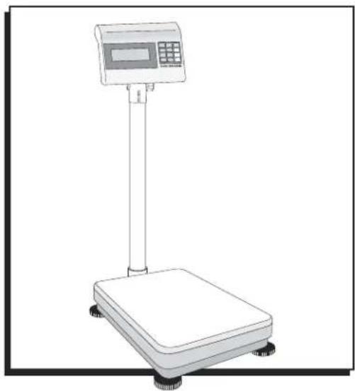
Line drawing of a digital balance scale with a digital display and control panel (no text or symbols)TOOLS NEEDED
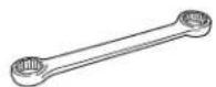
10 mm
Box Wrench
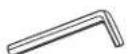
Allen Wrench
(Included)
PARTS
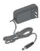
AC Adapter Support
Bracket
Tower Platform Base
natural_image
Illustration of a rectangular electronic device with four wheels and a small attached component (no text or symbols)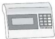
Display Indicator
ASSEMBLY
- Remove scale parts from packaging.
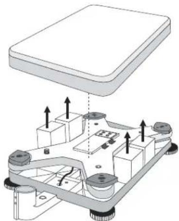
- Lift the scale pan off the platform base.
- Remove the four styrofoam blocks from the platform base. (See Figure 1)
- Replace the scale pan.
Figure 1
natural_image
Diagram of a mechanical assembly with labeled components and directional arrows (no text or symbols)ASSEMBLY CONTINUED
- Place the scale on the stable, level surface on which it is intended to be used.
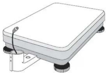
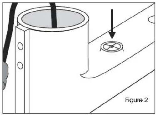
- Using the bubble level on the base bracket as a guide, adjust the four leveling feet until scale is level. (See Figure 2)
natural_image
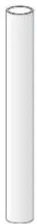
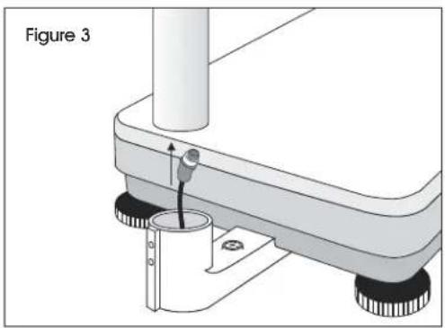
Technical diagram showing a cylindrical component with a circular hole and a separate circular feature, labeled Figure 2 (no text or symbols on the diagram itself)- Feed the data cable from the base bracket through the tower. (See Figure 3)
natural_image
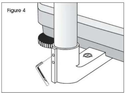
Mechanical assembly diagram showing a lever mechanism with a person inserted, labeled as Figure 3 (no text or symbols on the diagram itself)- Tighten the set screws in the base bracket using the included Allen wrench. (See Figure 4)
natural_image
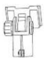
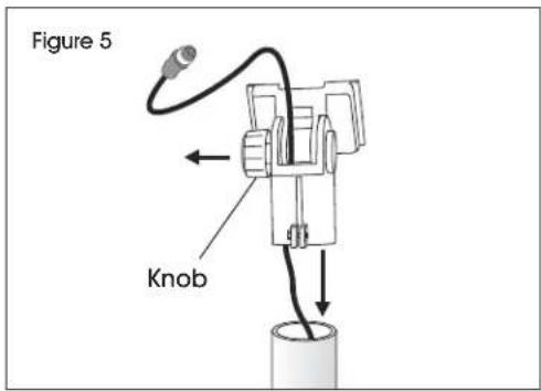
Technical diagram of a mechanical assembly with a cylindrical component and base mount (no text or symbols)- Feed the data cable through the support bracket by unscrewing the knob and pulling the support bracket pieces apart. (See Figure 5)
- Once data cable is threaded through support bracket as shown, tighten the knob and place the support bracket on the tower. (See Figure 5)
text_image
Figure 5 Knob-
Tighten the bolt at the base of the support bracket using a 10 mm box wrench.
-
Slide the display Indicator onto the support bracket. Adjust the angle of the display by loosening the knob on the support bracket. Tighten the knob when finished adjusting the angle. (See Figure 6)
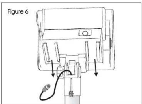
text_image
Figure 6- Plug the data cable and the AC adapter into the display indicator. (See Figure 7)
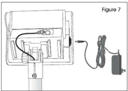
natural_image
Diagram of a device with cable and power cord, labeled Figure 7 (no text or symbols on diagram itself)COUNTING FUNCTION
- Prior to use, connect the AC adapter and monitor cable.
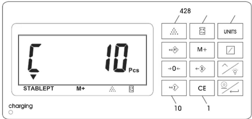
- This scale has fixed samples of 10, 20, 50 and 100 pieces.
-
The larger sample sizes will provide you with a more accurate unit weight.
-
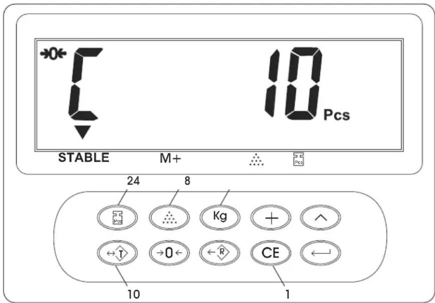
Prior to placing any object onto the scale, press the CE key (1). (See Figure 8)
- Select the fixed sample key of 10, 20, 50, 100 pieces (2). (See Figure 8)
- Place the requested number of samples onto the scale.
- Press the COUNT key (4). (See Figure 8)
- Remove all parts from the scale.
- Place the desired number of pieces onto the scale. This will provide an accurate count reading.
- Remove all parts from the scale.
- For the H-670 and H-4593: Press the UNITS key (8) to return to the weight display screen. (See Figure 8)
- For the H-747 and H-794: Press the Kg key (8) to return to the weight display screen. (See Figure 8)
- Press the TARE key (10) to zero out the weight of a container being used to hold parts. (See Figure 8)
text_image
STABLEPT M+ 10 Pcs charging 428 UNITS M+ →O← R CE 10 1H-670 & H-4593

text_image
0* T 10 Pcs STABLE M+ 248 Kg + ^ ←T →O ← R CE ← 10 1H-747 & H-794
Figure 8
CALIBRATION INSTRUCTIONS

NOTE: Scale can only be accurately calibrated using standard calibrated scale weights. Using non-calibrated weights may result in inaccurate scale calibration. Nothing should be on the scale and scale should be level.
ACTIVATE WEIGHT CALIBRATION MODE

- Switch the mini jumper SWA1 to "ADJ" position. Adjust is down; Lock is up. The switch is located under a panel on the right side of the keypad housing.
- Turn on the scale. As scale counts down to zero, press and hold the ZERO key until the software version (ex: 02018) appears on the display.
- Release ZERO key. F appears in display.
- Press ENTER key. Display shows 2Ero.
- Press ENTER key. Display shows 0---, -CHg .

- Press UNITS or Kg key to set scale to lb or kg as needed.

- Use the UP and ENTER keys to preset the weight being used to calibrate the scale. The UP key sets the number and the ENTER key moves right one digit.
Example: To set a weight of 3.0 kg, you would press the ENTER key three times to move right three spaces and the UP key three times to enter the number 3.
- Place your calibrated weight on the scale.
- Press ENTER key. Display shows WRITE.
• Scale displays weight and beeps. - Scale is calibrated, it will now return to weighing mode automatically.
- Switch the mini jumper SWA1 back to "LOCK."
natural_image
Line drawing of a digital scale instrument with a control panel and display (no text or symbols)natural_image
Diagram of a mechanical assembly with labeled components and directional arrows (no text or symbols)natural_image
Diagram of a device with cable and power cord, no text or symbols presenttext_image
10 Pcs STABLE PT M+ charging 428 UNITS PT M+ →0← R CE 10 1H-670 y H-4593
text_image
*0* 1 10 Pcs STABLE M+ 24 8 Kg + ^ ←T →0 ←R CE ← 10 1H-747 y H-794
natural_image
Line drawing of a digital scale instrument with a control panel and display (no text or symbols)natural_image
Illustration of a rectangular electronic device with four legs and a small attached component (no text or symbols)plateforme
natural_image
Diagram of a mechanical or electronic component with directional arrows indicating movement or force (no text or symbols present)MONTAGE SUITE
natural_image
Technical diagram showing a cylindrical component with a circular inset and an arrow pointing to it, labeled 'Figure 2' (no text or symbols on the diagram itself)natural_image
Technical diagram of a mechanical assembly with a cylindrical component and mounting base (no text or symbols)natural_image
Diagram of a device with cable and power cord connected to a battery (no text or symbols)GUIDE DE RÉFÉRENCE RAPIDE
FONCTION DE COMPTAGE
text_image
10 Pcs STABLE PT M+ charging 428 UNITS PT M+ →0← R CE 10 1H-670 et H-4593

text_image
*0* 1 10 Pcs STABLE M+ 24 8 Kg + ^ ←T →0 ←R CE ← 10 1H-747 et H-794
Figure 8
INSTRUCTIONS D'ÉTALONNAGE


