
H-5837 - Scale Uline - Free user manual and instructions
Find the device manual for free H-5837 Uline in PDF.

User questions about H-5837 Uline
0 question about this device. Answer the ones you know or ask your own.
Ask a new question about this device
Download the instructions for your Scale in PDF format for free! Find your manual H-5837 - Uline and take your electronic device back in hand. On this page are published all the documents necessary for the use of your device. H-5837 by Uline.
USER MANUAL H-5837 Uline
ULINE H-5836, H-5837 WASHDOWN PLATFORM SCALE
1-800-295-5510 uline.com
TOOLS NEEDED
2 mm Allen Wrench 4.5 mm Allen Wrench Phillips Screwdriver
natural_image
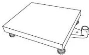
Line drawing of a digital scale with four legs and a digital display on top (no text or symbols)PARTS
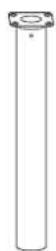
Column x 1

text_image
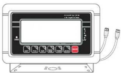
Diagram of an electronic device front panel with labeled buttons and ports, including a display screen and cable connections.Display Indicator x 1

natural_image
Line drawing of a rectangular electronic device with wheels and a side-mounted bracket (no text or symbols)Platform Base x 1
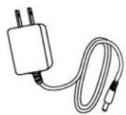
AC Adapter x 1
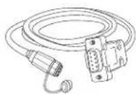
RS-232 Adapter x 1
SETUP

WARNING! Disconnect all power to the scale before installing, cleaning or servicing. Failure to do so could result in bodily harm or damage to the scale.
SELECTING THE LOCATION
The scale should always be used in an environment that is free from excessive air currents, corrosives, vibration and temperature or humidity extremes. These factors will affect displayed weight readings.
Avoid placing the scale next to or near:
- Open windows or doors.
• Air conditioning or heat vents.
• Vibrating, rotating or reciprocating equipment. - Magnetic fields.
• Equipment that generates magnetic fields. - Direct sunlight.
• An unstable work surface.
• A dusty environment. - Large users of electricity, like welding equipment or large motors.
• Unstable power sources.
UNPACKING THE SCALE
- Remove the scale parts from packaging.
- Place the scale on a flat surface.
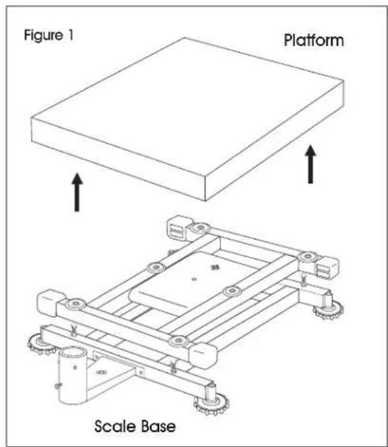
- Remove the platform from top of the scale base. (See Figure 1)
text_image
Figure 1 Platform Scale Base- Remove the styrofoam pad from under the platform.
SETUP CONTINUED
REMOVING THE SHIPPING SCREW
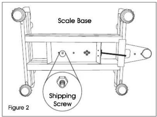
- Remove shipping screw from bottom of the scale base using a 2 mm Allen wrench. (See Figure 2)
text_image
Scale Base Shipping Screw Figure 2INSTALLING THE PLATFORM
- Remove protective covering from the scale platform.
- Place the platform on top of the scale base.

CAUTION! Do not press down with excessive force. This could damage the load cell.
LEVELING
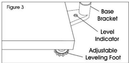
- The scale is equipped with a level indicator located on the back of the scale on the base bracket. (See Figure 3)
text_image
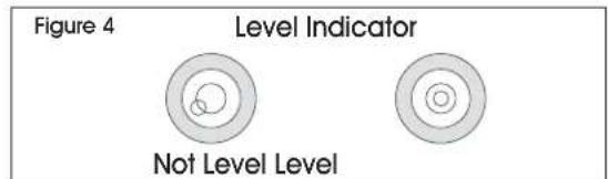
Figure 3 Base Bracket Level Indicator Adjustable Leveling Foot- Use the adjustable leveling feet located on the bottom of the scale until the bubble appears in the center of the indicator. (See Figure 4)
text_image
Figure 4 Level Indicator Not Level Level
NOTE: Check the level indicator every time scale is moved to a new location to verify scale is balanced.
ASSEMBLING THE COLUMN
- Unscrew the carriage bolt in the column using a Phillips screwdriver and detach the support bracket from the column. Unscrew four small Phillips head bolts from the support bracket. Set column, support bracket, carriage bolt and small Phillips head bolts aside.
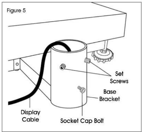
- On the base bracket, loosen two set screws using a 2 mm Allen wrench and the socket cap bolt using a 4.5 mm Allen wrench. (See Figure 5)
text_image
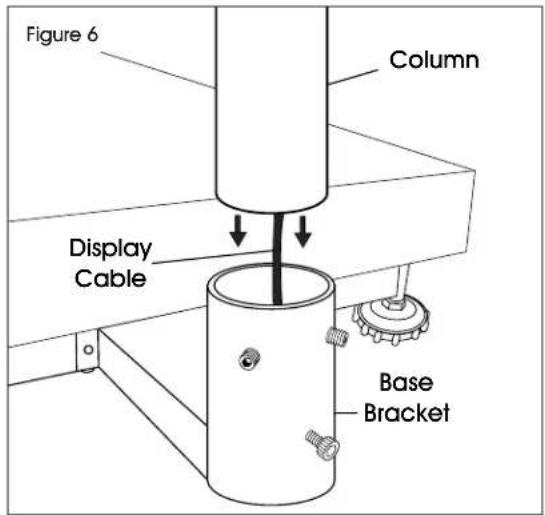
Figure 5 Set Screws Base Bracket Display Cable Socket Cap Bolt- Insert column into base bracket. Make sure column rests on the bottom of the base bracket. (See Figure 6) Pull display cable all the way through the column so no slack is under the platform.
text_image
Figure 6 Column Display Cable Base Bracket- Secure column with set screws using a 2 mm Allen wrench and with the socket cap bolt using a 4.5 mm Allen wrench, but do not tighten.
SETUP CONTINUED
ATTACHING INDICATOR TO THE COLUMN
- Place the indicator bracket onto the top (flat side) of the support bracket. Align the large center holes and four small holes.
- Insert four small Phillips head bolts through the small holes on top of the indicator bracket and the support bracket. Tighten until pieces are securely attached.
- Feed black display cable from the display indicator through the large center holes in the indicator bracket and support bracket. Connect to the display cable end at the top of the column by aligning holes and pushing connectors together. Twist a quarter of a turn to lock into place. (See Figure 7)
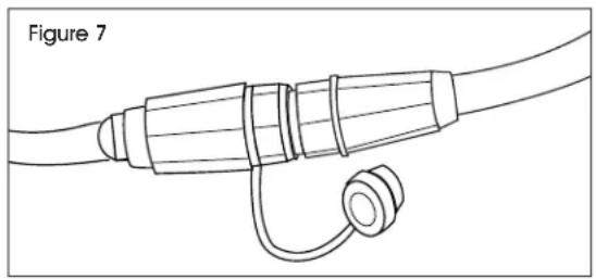
natural_image
Line drawing of a cable with a coiled cable and connector (no text or symbols)- Place support bracket into the column with the display facing the platform. Pull display cable all the way through the column so excess is under the base bracket. Make sure RS-232 cable is on the back of the display. (See Figure 8)
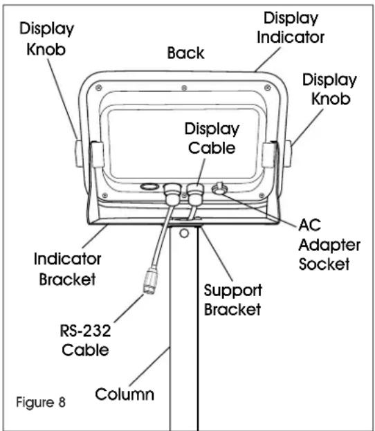
text_image
Display Knob Back Display Indicator Display Knob Display Cable AC Adapter Socket Indicator Bracket Support Bracket RS-232 Cable Column Figure 8- Tilt display to desired position.
- Insert carriage bolt back into the column and tighten.
- Tighten base bracket set screws and socket cap bolt.
CONNECTING POWER
The scale can operate continuously by connecting the AC adapter to an outlet or operate eight hours on a fully charged battery.

WARNING! Only use the original AC adapter and battery that came with the scale. Using an alternative AC adapter or battery could damage the scale.
AC ADAPTER
Plug the AC adapter into the AC adapter socket on the back of the indicator. Plug the AC adapter plug into a standard 110 volt outlet.

WARNING! When AC adapter is not in use, AC adapter socket must be capped. Leaving the socket uncapped during water exposure could result in damage.

NOTE: Verify the local voltage and receptacle type are correct for the scale.
BATTERY
The scale is equipped with a rechargeable battery.
When the battery voltage is low, a battery symbol will appear in the lower left-hand corner of the display. After 15 minutes, the backlight will start to flicker and the display will show 8± t / 0 . The scale will automatically turn off 30 minutes after the symbol appears.
CHARGING THE BATTERY
When the battery indicator ( ) appears in the lower left-hand corner of the display, the battery needs to be recharged.
Plug the AC adapter into a power source to charge the battery. Scale does not need to be turned on. It will take 12 hours to fully charge the battery.
The charging indicator is located on the left side of the display, above the word CHARGE. The indicator light color will change to indicate the battery status:
- RED – Battery needs to be recharged.
- ORANGE – Battery is being charged.
- GREEN – Battery is fully charged.
BATTERY MAINTENANCE
Recharge battery every three months when not in use.
If the scale is not used for an extended period of time, remove the battery from the battery compartment to avoid leakage. Store the battery in a sealed bag or box in a dry, temperate environment.
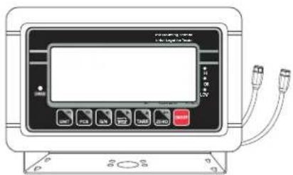
OVERVIEW OF CONTROLS
DISPLAY AND KEYPAD
text_image
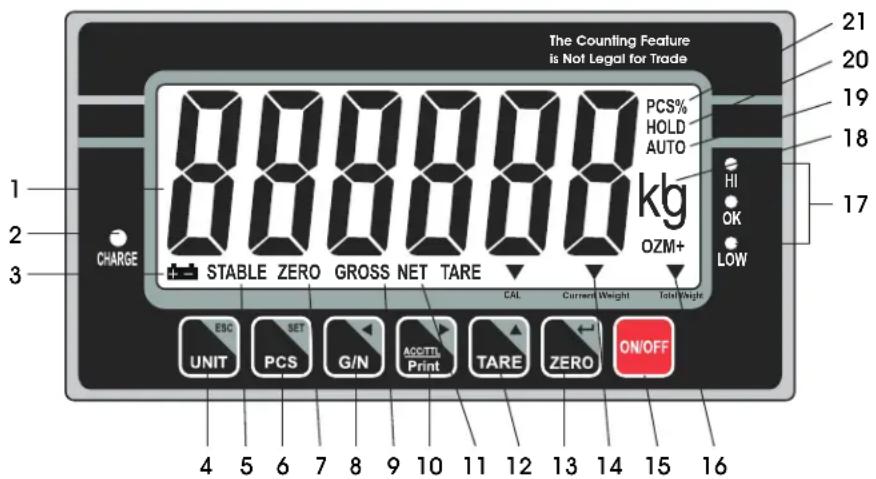
The Counting Feature is Not Legal for Trade PCS% HOLD AUTO kg OZM+ HI OK LOW 1 2 3 CHARGE STABLE ZERO GROSS NET TARE CAL Current Weight Total Weight ESC SET G/N ACC/TL Print TARE ZERO ON/OFF UNIT PCS G/N ACC/TL Print TARE ZERO ON/OFF 4 5 6 7 8 9 10 11 12 13 14 15 16KEYPAD PARTS
| # DESCRIPTION |
| 4 UNIT / ESC Key |
| 6 PCS / SET Key |
| 8 G/N Key |
| 10 ACC/TTL Print Key |
| 12 TARE Key |
| 13 ZERO Key |
| 15 ON/OFF Key |
DISPLAY AND KEYPAD DEFINITIONS
| # | NAME DESCRIPTION | |
| 1 | DISPLAY | Displays the total weight, unit weight and number of counted items. |
| 2 | CHARGE | Charging indicator. Indicates the battery charging status. |
| 3 |  | Battery indicator. Indicates battery is low and needs to be recharged. |
| 4 | UNITESC | Units key. Used to change weighing unit.ESC key. Used to exit the set-up menu. |
| 5 | STABLE | Stable indicator. Indicates the scale weight is stable. |
| 6 | PCSSET Setup | Count key. Used to enter the counting operation.menu key. Used to enter setup menu. |
| 7 | ZERO Zero indicator. Indicates the scale is at zero. | |
| 8 | G / N◀ | Gross/Net Weight key. Used to show the net or gross weight.Left arrow key. Used to move the active digit to the left. |
| 9 | GROSS | Gross indicator. Indicates scale is displaying the gross weight. |
| 10 | ACC / TTL Print▶ | Accumulation key. Used to enter and show accumulated weights or counts in memory.Print key. Used to send data to a printer or PC.Right arrow key. Used to move the active digit to the right. |
| # | NAME DESCRIPTION | |
| 11 | NET | Net indicator. Indicates scale is displaying the net weight. |
| 12 | TARE▲ | Tare key. Used to zero out the weight of a container being used to hold small parts.Value increment key. Used to change the active digit value. |
| 13 | ZERO Zero← | key. Used to clear and zero the display.Enter key. Used to enter the selected menu, sub-menu and setting. |
| 14 | CURRENT WEIGHT | Current weight indicator. Indicates current weight in accumulation mode. |
| 15 | ON / OFF | On/off key. Used to turn the scale on or off. |
| 16 | TOTAL WEIGHT | Total weight indicator. Indicates total weight in accumulation mode. |
| 17 | HI / OK / LOW | Limits indicator. Indicates the high-low limits in weighing and counting. |
| 18 | LB / OZ / KG | Weighing unit indicator. Indicates current weighing unit. |
| 19 | AUTO | Automatic accumulation indicator. Indicates the scale is in automatic accumulation mode. |
| 20 | HOLD | Hold indicator. Indicates the scale is in dynamic weighing mode. |
| 21 | PCS% | Counting mode indicator. Indicates scale is in counting mode. |
OPERATION
PRIOR TO USE
- Fully charge the battery before using scale for the first time.
- Let the scale warm up for 15 minutes before use.

WARNING! Never drop items onto the platform. The scale is a sensitive precision instrument.
WARNING! Do not exceed the scale capacity and overload the scale.
WARNING! Do not stack items on the scale platform when the scale is not in use.
TURNING THE SCALE ON/OFF
ON/OFF key is located in the lower right hand corner of the display.

CAUTION! Never power the scale on with weight on the platform.

- To turn the scale on, press the ON/OFF key. The scale will show the version and enter a self-test mode. After completing the self-test, the scale will enter the weighing application mode.

- To turn the scale off, press the ON/OFF key
CHANGE UNIT OF MEASURE
Press the UNIT key UNIT until the desired weighing unit appears – lb, oz or kg.
CALIBRATION
The scale is pre-calibrated during production. You must use a precision test weight to properly calibrate the scale. The test weight CANNOT exceed the scale's capacity.

NOTE: Calibration can be done in English (lb.) and Metric system weight (kg) at the scale's full capacity.
CALIBRATION WEIGHTS
| Model # Lb. Kg | ||
| H-5836 100 lb. | 50 kg | |
| H-5837 200 lb. | 100 kg |
SINGLE POINT CALIBRATION (SPAN)
Single point calibration uses two calibration points, zero and full weight capacity of the scale.
- Turn on the scale.
- Press the PCS/SET key PCS during the self-test.
- Display will be show n .
- Press the G/N key G/N, then the UNIT/ESC key UNIT and then the TARE key TARE. Display will show po chk.
-
Press the TARE key TARE until display shows p ≥ 2 .
-
Press the ZERO key ZERO to confirm. Press the TARE key TARE until display shows sign.
-
Press the ZERO key ZERO to confirm. Press the TARE key TARE to select cal.
-
Press the ZERO key ZERO to confirm.
-
Press the ZERO key ZERO to enter calibration, display will show unid.
-
Remove all the weight from the platform.
-
When indicator is stable, press the ZERO key to confirm.
-
Display will show the last calibration weight. Change the calibration weight value to the full capacity of the scale. Press the G/N key and the ACCT/TTL/Print key to change the active digits and press the TARE key change the value.
-
When the calibration value is correct, press the ZERO key ZERO to confirm.
-
Display will show load.
-
Place the calibration weight on the platform.
-
When indicator is stable, press the ZERO key ZERO key to confirm.
-
Display will return to weighing mode.
OPERATION CONTINUED
ZERO
If there is a minor weight displayed without anything on the platform, press the ZERO key ZERO to clear the display. Zero indicator will be shown on the display.
TARE
When weighing an item that is in a container, taring stores the container weight to memory so only the item weight is displayed.
To store tare weight into memory and set display to zero:
- Place an empty container on the platform.
- Press the TARE key TARE. The net indicator will be displayed on the bottom of the display.
- The container's weight is then stored in the scale's memory and zero is displayed.
- Add pieces to the container. As the pieces are added, their net weight will be displayed.
- Press the G/N key to display the gross weight and net weight.
- Removing the container from the platform will cause the scale to display the container's negative weight. Pressing the TARE key will readjust the scale to zero.
WEIGHING
Use this mode to weigh items.
- Place item to be weighed on the scale platform. Weight will be show in the display.
COUNTING
Use this mode to count parts of uniform weight.
SAMPLE OF UNIT WEIGHT
The scale cannot determine how many pieces are on a platform without a sample.
- Press the PCS/SET key to enter the counting mode. P IO will be shown on the display.
- Press the TARE key to change the sample quantity - 10, 20, 50, 100 or 200 units.
P10/P20/P50/P100/P200
-
Place objects intended for sampling on the platform and press the ZERO key ZERO . "----" will be shown on the display followed by the sample quantity.
-
Place remaining objects on the platform. The total quantity will be displayed.
- Press the PCS/SET key to exit to the normal weighing mode.
LACK OF UNIT WEIGHT
The minimum weight must be at least 20 times the scale accuracy for accurate calculations. Reference the table below for minimum weights.
| Model # | Minimum Piece Weight | Minimum Sample Weight |
| H-5836 0.01 lb. | 0.4 lb. | |
| H-5837 0.025 lb. | 1 lb. |
If the unit weight is too light, another scale is needed. Continuing to use this scale will result in less accurate results.
CHECK WEIGHING
Use this mode to set a number for a weighing check. When the weight of the objects on the platform is between the preset checking numbers, the alarm sound beeps repeatedly.
SET CHECK WEIGHT

NOTE: Weight on platform must be equal to or greater than minimum weight in order for check weighing mode to operate accurately.
- Press and release the UNIT key and the PCS/SET key simultaneously. SEE H will be shown on the display.
- To set the high limit, press the ZERO key ZERO . 00000 will be shown on the display with the last digit blinking.
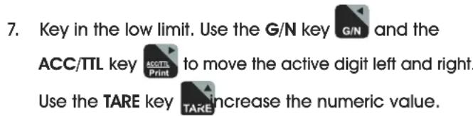
- Key in the high limit. Use the G/N key G/N and the ACC/TTL key ACC/TTL to move the active digit left and right. Use the TARE key TARE to increase the numeric value.
- Press the ZERO key ZERO to confirm. S E H will be shown on the display.
- Press the TARE key until Set L is shown on the display.
- To set the low limit, press the ZERO key ZERO . 00000 will be shown on the display with the last digit blinking.
OPERATION CONTINUED
text_image
7. Key in the low limit. Use the G/N key G/N and the ACC/TTL key ACCTEL to move the active digit left and right. Use the TARE key TARE increase the numeric value.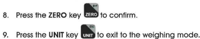
text_image
8. Press the ZERO key ZERO to confirm. 9. Press the UNIT key UNIT to exit to the weighing mode.- Place item to be weighed on the scale platform. Weight will be shown on the display. Scale will beep if weight is within specified high-low range. Indicators on right of the display will show if weight is above (HI), below (LO) or within (OK) the specified range.
CLEAR CHECK WEIGHT
- Press the UNIT key UNIT and the PCS/SET key PCS at the same time until SET H is shown on the display.
- To clear the high limit, press the ZERO key ZERO . 00000 will be shown on the display with the last digit blinking.
- Press PCS key SET to clear out the value.
- Press the ZERO key ZERO to confirm. Set H will be shown on the display.
- Press the TARE key TARE until Set L is shown on the display.
- To clear the low limit, press the ZERO key ZERO . 00000 will be shown on the display with the last digit blinking.
- Press the PCS key PCS to clear out the value.
- Press the ZERO key ZERO to confirm.
- Press the UNIT key UNIT to exit to the weighing mode.
ACCUMULATION
Use this mode to measure the cumulative weight or counting values of a sequence of items. The maximum number of samples is 99 entries or the scale weight capacity.
MANUAL ACCUMULATION
NOTE: Weight on platform must be equal to or greater than minimum weight in order for accumulation mode to operate accurately.
- Follow steps above to weigh or count items on the scale platform.
- Once the stable indicator is shown on the display, press the ACC/TTL Print key . ACC I will be shown on the display and the total value will be displayed for three seconds. Weighing or counting value will be stored into memory. If a printer is connected, the data will print.
- Remove items from platform. Display will return to zero or a negative value.
- Add additional items to platform.
- Once the stable indicator is shown on the display, press the ACC/TTL Print key 📄 new data will be added to memory. Continue until all data is added.
RECALL DATA
- With nothing on the platform, press and release the ACC/TTL Print key 📄 display the total value of items stored to memory. The number of accumulated values will be displayed, ACC #, followed by the total accumulated value for three seconds.
CLEAR DATA
- To clear data stored to memory, press and hold the G/N key G/N and the ACC/TTL Print key ACC/TTL Print at the same time.
- ACC 0 will be shown on the display. All the accumulated values will be cleared from memory.
OPERATION CONTINUED
AUTOMATIC ACCUMULATION
Use this application to automatically add weighing and counting values to the scale memory and to print values if a printer is connected.

NOTE: Automatic accumulation must be enabled. See Setup section on page 10.
When in the automatic accumulation application, the auto indicator will be shown in the upper right hand corner of the display.
- Place items to be weighed or counted on the scale platform.
- Once the stable indicator is shown on the display, the scale will make a beeping sound.
- RCC I will be shown on the display and the total value will be displayed for three seconds. Weighing or counting value will be stored into memory.
- Remove items from platform. Display will return to zero or a negative value.
- Add additional items to platform. New data will be added to memory. Continue until all data is added.
- To recall data and clear data, see sections above.
DYNAMIC WEIGHING
Use this mode to weigh moving items.
- Press and release the TARE key TARE and the
ZERO key zand the same time to enter the dynamic weighing mode. The hold indicator will appear in the upper right hand corner of the display.
-
Place item to be weighed on the scale platform. Once the stable indicator appears, the final weight will be shown on the display.
-
Press and release the TARE key TARE and the
ZERO key zero the same time to exit the dynamic weighing mode.
RS-232
To use the RS-232 port, connect the gray RS-232 adapter to the gray RS-232 cable on the display indicator. (See Figure 9)
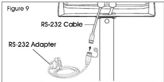
text_image
Figure 9 RS-232 Cable RS-232 AdapterSPECIFICATIONS
RS-232 output of weighing data:
- Code: ASCII
• Data Bits: 8 data bits - Parity: No Parity
- Baud Rate: 600bps – 900bps selectable.
RS-232 (9-PIN D TYPE CONNECTOR)
| Pin 2 | RXD | Input | Receiving Data |
| Pin 3 | TXD | Output | Transmission Data |
| Pin 5 | GND | — | Signal Ground |
9 Pin D Connector
| Scale | Computer/Printer |
| Pin 2: | Pin 3 |
| Pin 3: | Pin 2 |
| Pin 5: | Pin 5 |
Check Weighing Output
Pin 1: VB
Pin 4: Vcc 5v (Output)
Pin 5: Com (Ground)
Pin 6: Ok (Output)
Pin 7: Low (Output)
Pin 8: Hi (Output)
Pin 9: Beep (Output)
CONTINUOUSLY OUTPUT PROTOCOL
Weighing Mode
| , | / L | k | g | CR | LF | |||||||||||
| -HEADER 1 - | -HEADER 2 - | - NEIGH DATA - | - NEIGH UNIT - | TERMINATOR | ||||||||||||
Counting Mode
| P | C | S | : | ∪ | p | c | s | CR | LF | |||||||
| -∅TY-UNT | ||||||||||||||||
HEADER1: ST=STABLE, US=UNSTABLE
HEADER2: NT=NET, GS=GROSS
OPERATION CONTINUED
Con2:
| Header0 | Header1 | Header2 | Header3 | Weight1 | Weight2 | Weight3 | Weight4 | Weight5 | Weight6 | Tare1 | Tare2 | Tare3 | Tare4 | Tare5 | Tare6 | Terminator1 | Terminator2 |
Header0=02H
Header1 follow decimal point
Decimal point=0, header1=22H
Decimal point=1, header1=23H
Decimal point=2, header1=24H
Decimal point=3, header1=25H
Decimal point=4, header1=26H
Header2 follow weigh status, default value=20H
If in net mode (tare value not 0), header2=header2|01H
If gross weight "-" header2=header2|02H
If overload or gross weight "-" header2=header2|04H
If unstable, header2=header2|08H
If weighing unit=kg, header2=header2|10H
Header3 follow weighing unit
If weighing unit=g, header3=21H
If weighing unit=oz, header3=23H
Weight1 \~ weight6: weighing data
Tare1 \~tare6: tare value
Terminator1: 0DH
Terminator2: 0AH
Con3:
| Header0 | Header1 | Weight1 | Weight2 | Weight3 | Weight4 | Weight5 | Weight6 | Weight7 | Unit1 | Unit2 | Status | Terminator1 | Terminator2 |
HEADER0=01H
Header1 follow weight "+" or "-"
When weight "+", header1="+" when weight "-", header="-
Weight1\~weight7: weight data (include decimal point)
Unit1 \~ unit2: weight unit
Status: when stable, status=0, when unstable, status=1
Terminator1: 0DH
Terminator2: 0AH
LEGAL FOR TRADE
When the indicator is used in trade or a legally controlled application, it must be set up, verified and sealed in accordance with local weights and measures regulations. It is the responsibility of the purchaser to ensure that all pertinent legal requirements are met.
CALIBRATION
- Break the seal on the indicator housing.
- Open the housing.
- See calibration process on page 5. Complete steps 1-5.
- After step 5, press the calibration switch on the mainboard. (See Figure 10)
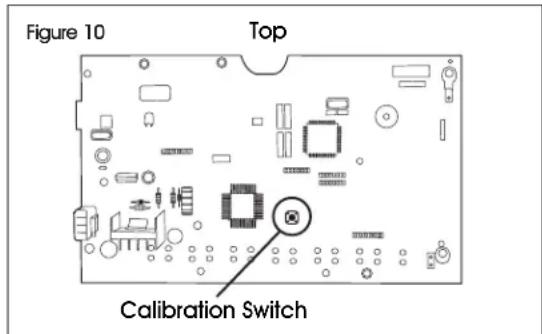
text_image
Figure 10 Top Calibration Switch- Complete remaining calibration steps on page 5.
VERIFICATION
The local weights and measures official or authorized service agent must perform the verification procedure.
SEALING
The local weights and measures official or authorized service agent must apply a security seal to prevent tampering with the settings.
SETUP MENU
BACKLIGHT
At startup, the backlight will automatically turn on when the scale is in use. Enter this menu to change the backlight setting.

- Press and hold the ZERO key ZERO for 3 seconds. SET bF will be shown on the display.

-
Press the ZERO key ZERO to enter the backlight menu.
-
Press the TARE key TARE until the desired setting is shown on the display.
-
AU – Backlight automatically turns on when the scale is in use.
- on - Backlight is always on.
-
oFF - Backlight is never on.
-
Press the ZERO key ZERO to select the new setting.
-
Press the UNIT key UNIT to exit the sub menu.


AUTO POWER-OFF
When the auto power-off time is enabled, the scale will automatically turn off when there has been no load on the platform and the scale is stable at zero position for a specified period of time (in minutes). At startup, the auto power-off is disabled. Enter this menu to turn the auto power-off feature on or off.
- Press and hold the ZERO key ZERO for three seconds. SET bF will be shown on the display.
- Press the TARE key TARE until SET of F is shown on the display.
- Press the ZERO key ZERO to enter the auto power-off menu.
-
Press the TARE key TARE until the desired setting is shown on the display.
-
oFF -Auto power-off is off.
• oF 5 – Auto power-off at 5 minutes.
• oF IS – Auto power-off at 15 minutes. -
Press the ZERO key ZERO to select the new setting.
-
Press the UNIT key UNIT to exit the sub menu.
HIGH/LOW LIMIT BEEPING SOUND
At startup, the beeping sounds are set to beep when weights are inside the limits. Enter this menu to change the beeping sound setting.
- Press the UNIT key UNIT and the PCS/SET key PCS at the same time until SET H is shown on the display.
- Press the TARE key until bEEP is shown on the display.
- Press the ZERO key ZERO to enter the submenu.
- Press the TARE key TARE until desired setting is shown on the display.
• nonE - No beeping sounds.
- oF- Beeping sounds between the limits.
- nG - Beeping sounds outside of the limits.
-
Press the ZERO key ZERO to select the new setting.
-
Press the UNIT key EBC UNIT to exit to the weighing mode.
ENABLE DYNAMIC WEIGHING
At startup, the dynamic weighing mode is enabled. Enter this menu to turn the dynamic weighing mode on or off.
- Turn on the scale and press the PCS key during the self-test. P_n will be shown on the display.
- Press the G/N key G/N, then the UNIT key UNIT and then the TARE key TARE. Po CHF will be shown on the display.
- Press the TARE key TARE until P3 a th is shown on the display.
- Press the ZERO key ZERO to enter the menu. anm will be shown on the display.
- Press the ZERO key ZERO to enter the sub menu.
- Press the TARE key TARE until the desired setting is shown on the display.
- on – Dynamic weighing is on.
- oFF -Dynamic weighing is off.
- Press the ZERO key ZERO to select the new setting.
- Press the UNIT key UNIT twice to exit the menu.
ENABLE ACCUMULATION, AUTO ACCUMULATION AND RS-232
At startup, the accumulation mode is enabled. Enter this menu to turn the accumulation and auto accumulation modes on or off and to set the RS-232 communication.
- Turn on the scale and press the PCS key PCS during the self-test. P_n will be shown on the display.
- Press the G/N key G/N, then the UNIT key UNIT and then the TARE key TARE. Po CHF will be shown on the display.
- Press the TARE key TARE until PI com is shown on the display.
- Press the ZERO key ZERO to enter the menu. Mode will be shown on the display.
SETUP MENU CONTINUED
-
Press the ZERO key ZERO to enter the sub menu.
-
Press the TARE key TARE until the desired setting is shown on the display.
-
Cont - Continuously sends data to printer.
- SE / - Sends data one time to printer when indicator is stable.
- ST C – Sends data continuously to printer when indicator is stable.
- PrI – Sends data one time to printer when the
- Cont - Continuously sends data to printer.
- SE / - Sends data one time to printer when indicator is stable.
- S C - Sends data continuously to printer when indicator is stable.
ACC/TTL Print key ACC/TTL Print pressed.
- Pr2 – Performs accumulation and sends data one time to printer when the ACC/TTL Print key is pressed.
- Ruto – Performs auto accumulation and auto print when indicator is stable and returns to 0.
- Pr2 – Performs accumulation and sends data one
time to printer when the ACC/TTL Print key is pressed. -
Ruto – Performs auto accumulation and auto print when indicator is stable and returns to 0.
-
Press the ZERO key ZERO to select the new setting.
-
Press the UNIT key ESC UNIT twice to exit the menu.
BAUD RATE
Baud rate is the RS-232 transmission speed. If using a printer, both the printer and the scale must be set to the same baud rate. At startup, the baud rate is set at 9,600. Enter this menu to change the baud rate setting
- Turn on the scale and press the PCS key PCS during the self-test. P_n will be shown on the display.
- Press the G/N key G/N, then the UNIT key UNIT and then the TARE key TARE. Po CHF will be shown on the display.
- Press the TARE key TARE until PI com is shown on the display.
- Press the ZERO key ZERO to enter the menu. Mode will be shown on the display.
- Press the TARE key TARE until Baud is shown on the display.
- Press the ZERO key ZERO to enter the sub menu.
- Turn on the scale and press the PCS key PCS during the self-test. P_n will be shown on the display.
- Press the G/N key G/N, then the UNIT key UNIT and
then the TARE key TARE. Po CHF will be shown on the display. - Press the TARE key TARE until PI com is shown on the display.
- Press the ZERO key ZERO to enter the menu. Mode will be shown on the display.
- Press the TARE key TARE until _aud is shown on the display.
-
Press the ZERO key ZERO to enter the sub menu.
-
Press the TARE key TARE until the desired setting is shown on the display.
600
• 1200
• 2400
• 4800
• 9600
- Press the ZERO key ZERO to select the new setting.
- Press the UNIT key UNIT twice to exit the menu.
PRINTER SET-UP
Enter this menu to select a printer.
- Turn on the scale and press the PCS key PCS during the self-test. P_n will be shown on the display.
- Press the G/N key, then the UNIT key UNIT and then the TARE key TARE. Po CHF will be shown on the display.
- Press the TARE key TARE until PI com is shown on the display.
- Press the ZERO key ZERO to enter the menu. Mode will be shown on the display.
- Press the TARE key TARE until P_type is shown on the display.
- Press the ZERO key ZERO to enter the sub menu.
-
Press the TARE key TARE until the desired setting is shown on the display.
-
EPUP - Ticket printer
• LP-50 - Label Printer -
Press the ZERO key ZERO to select the new setting.
- Press the UNIT key UNIT twice to exit the menu.


- Press the TARE key TARE until the desired setting is shown on the display.


- Press the ZERO key ZERO to select the new setting.

- Press the UNIT key UNIT twice to exit the menu.
BAUD RATE
Baud rate is the RS-232 transmission speed. If using a printer, both the printer and the scale must be set to the same baud rate. At startup, the baud rate is set at 9,600. Enter this menu to change the baud rate setting


MAINTENANCE
CLEANING

CAUTION! Disconnect the unit from the AC adapter and cap AC adapter socket before cleaning. Do not use with pressure washers or other high pressure water jets. Rated IP65 for use with hoses.
Use a stainless steel cleaning solution for the stainless steel indicator housing and platform.
Apply cleaner to a clean, damp cloth and wipe surface. Dry thoroughly.
Use a mild detergent for the display and keypad.

WARNING! Do not use solvents, chemicals, alcohol, ammonia or abrasives.
TROUBLESHOOTING
| ERROR CAUSE RECOMMENDATIONS | ||
| Inaccurate weights Shipping | screw needs to be removed. | Remove shipping screw. |
| Scale needs to be recalibrated. | Recalibrate the scale. | |
| Err 4 | Scale needs to be recalibrated. | Recalibrate the scale. |
| Err 5 | Load cell connectivity issue. | Verify all load cell connection wires are secure. |
| AD board connectivity issue. | Verify all AD board connection wires are secure. | |
| -0L- | Maximum capacity exceeded. | Remove load from platform. |
| 8st10 | Battery needs to be recharged. | Recharge battery. |
If the problem persists or the troubleshooting section does not resolve or describe your problem, contact Uline Customer Service at 1-800-295-5510.
ULINE H-5836, H-5837
800-295-5510
uline.mx
BÁSCULA IMPERMEABLE DE PLATAFORMA
natural_image
Line drawing of a digital scale with four legs and a digital display on top (no text or symbols)PARTES

1 Columna
text_image
Diagram of an electronic device front panel with labeled buttons and ports, including a display screen and cable connectors.1 Pantalla Indicadora
natural_image
Line drawing of a rectangular electronic component with mounting feet and a cylindrical protrusion (no text or symbols)natural_image
Line drawing of a cable with a coiled connector and a labeled diagram (no text or symbols on the diagram itself)text_image
The Counting Feature Is Not Legal for Trade PCS% HOLD AUTO kg OZM+ HI OK LOW 1 2 3 CHARGE STABLE ZERO GROSS NET TARE CAL Current Weight Total Weight ESC SET G/N ACCETI Print TARE ZERO ON/OFF UNIT PCS G/N ACCETI Print TARE ZERO ON/OFF 4 5 6 7 8 9 10 11 12 13 14 15 16PARTES DEL TECLADO
| Modelo No. Lbs. | Kg | |
| H-5836 100 lbs. | 50 kg | |
| H-5837 200 lbs. | 100 kg |
| Header0 | Header1 | Weight1 | Weight2 | Weight3 | Weight4 | Weight5 | Weight6 | Weight7 | Unit1 | Unit2 | Status | Terminator1 | Terminator2 |
TÍMULO0=01H
The Ground Truth image displays a single, solid horizontal line. According to Rule 2 (UNDERSCORE & LINE RULES), this is a stylistic or background line, not a placeholder underscore. Therefore, the OCR result must ignore it and output nothing or only meaningful text. The provided OCR content is "____", which consists of four underscores. This is an incorrect interpretation of the line as a placeholder, violating the rule that stylistic lines must be ignored. The OCR has hallucinated underscores where none should exist based on the GT's visual context. Hence, the OCR result is inconsistent with the Ground Truth.
a seleccionar la
natural_image
Line drawing of a digital scale with four legs and a digital display on top (no text or symbols)PIÈCES
text_image
IN OR ON OFF USB USB USB USBColonne x 1 Base de Idéplaretterficie X 1

natural_image
Line drawing of a rectangular electronic device with mounting feet and a side-mounted knob (no text or symbols)
Adaptateur CA x 1
natural_image
Line drawing of a cable with a coiled connector and a bulbous end (no text or symbols)text_image
The Counting Feature Is Not Legal for Trade PCS% HOLD AUTO kg OZM+ HI OK LOW 1 2 3 CHARGE STABLE ZERO GROSS NET TARE CAL Current Weight Total Weight ESC SET G/N ACCITIE Print TARE ZERO ON/OFF UNIT PCS G/N ACCITIE Print TARE ZERO ON/OFF 4 5 6 7 8 9 10 11 12 13 14 15 16TOUCHES DU CLAVIER
| # | DESCRIPTION |
| 4 | Touche UNIT / ESC |
| 6 | Touche PCS / SET |
| 8 | Touche G/N |
| 10 | Touche d'impressionACC/TTL Print |
| 12 | Touche de TARE |
| 13 | Touche de ZERO |
| 15 | Touche ON/OFF |
ACCUMULATION MANUELLE

EFFACEMENT DES DONNÉES
| Header0 | Header1 | Weight1 | Weight2 | Weight3 | Weight4 | Weight5 | Weight6 | Weight7 | Unit1 | Unit2 | Status | Terminator1 | Terminator2 |
EN-TÊTEO=01H


