H-5032 - Forklift Uline - Free user manual and instructions
Find the device manual for free H-5032 Uline in PDF.


User questions about H-5032 Uline
0 question about this device. Answer the ones you know or ask your own.
Ask a new question about this device
Download the instructions for your Forklift in PDF format for free! Find your manual H-5032 - Uline and take your electronic device back in hand. On this page are published all the documents necessary for the use of your device. H-5032 by Uline.
USER MANUAL H-5032 Uline
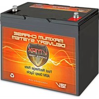
ULINE H-5032 PALLET TRUCK BATTERY
1-800-295-5510 uline.com
natural_image
Two types of wrench illustrations: a left-angle wrench and a multi-wheeled wrench (no text or symbols)5 mm Allen Wrench 13 mm Wrench
BATTERY REPLACEMENT INSTRUCTIONS
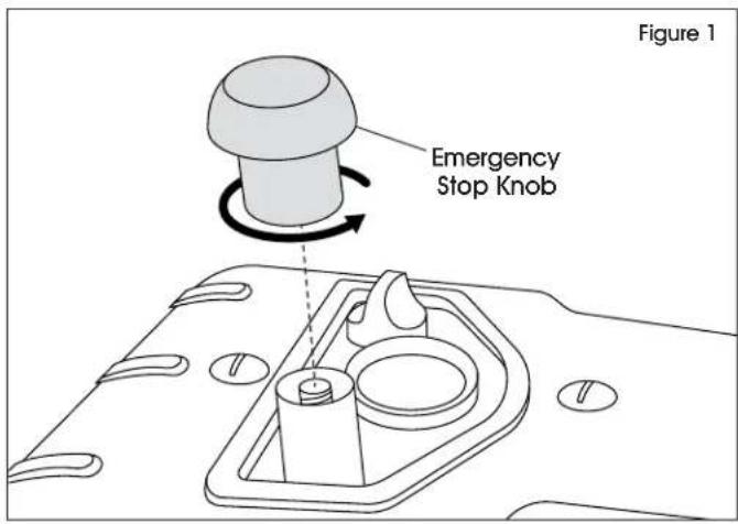
- Unscrew emergency stop knob from top of pallet truck. (See Figure 1)
text_image
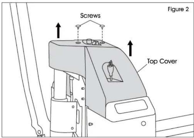
Figure 1 Emergency Stop Knob- Remove two screws on top cover and lift up to remove top cover. (See Figure 2)
text_image
Screws Figure 2 Top Cover- Lift forks to the highest position and turn off the unit.
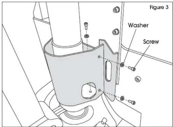
IMPORTANT! If batteries are dead, remove six screws and washers (three per side) with 5 mm Allen wrench from hydraulic guards to lift forks manually. (See Figure 3)
text_image
Figure 3 Washer ScrewBATTERY REPLACEMENT INSTRUCTIONS CONTINUED
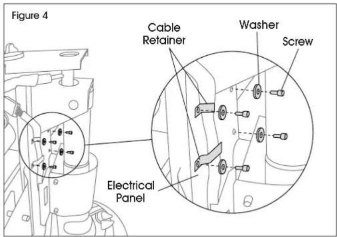
- Remove four screws and washers holding cable retainers and electrical panel in place using 5 mm Allen Wrench. (See Figure 4)
text_image
Figure 4 Cable Retainer Washer Screw Electrical Panel- Disconnect the three battery cables using 13 mm wrench. (See Figure 5)
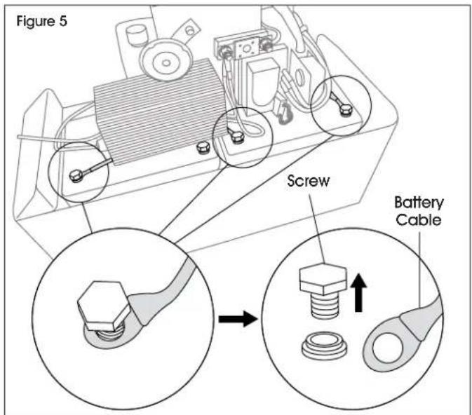
text_image
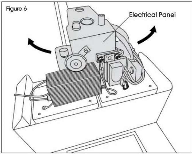
Figure 5 Screw Battery Cable- Rotate electrical panel left/right to clear batteries for removal. (See Figures 6-7)
text_image
Figure 6 Electrical Panel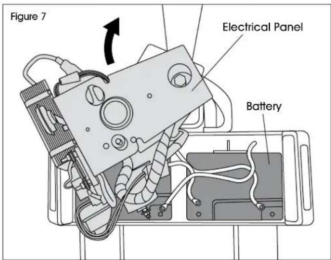
text_image
Figure 7 Electrical Panel Battery- Remove old batteries and replace with new batteries.
- Reposition electrical panel into place.
BATTERY REPLACEMENT INSTRUCTIONS CONTINUED
- Reconnect the battery cables using 13 mm wrench. (See Figure 8)
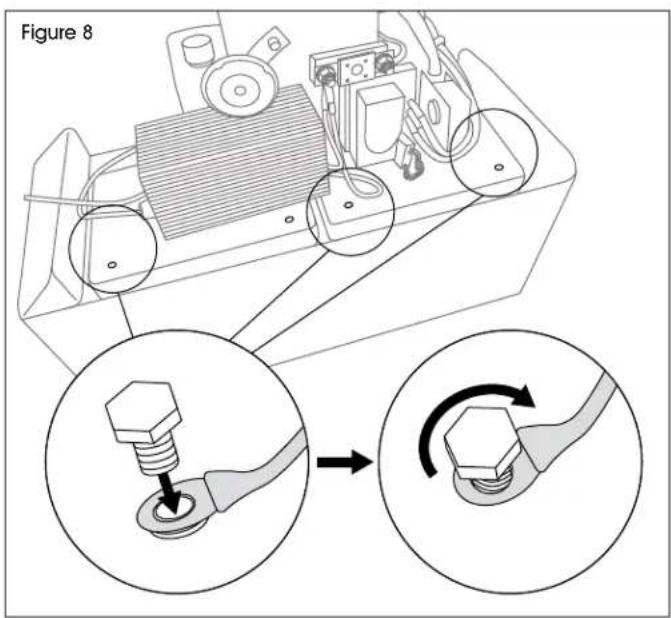
text_image
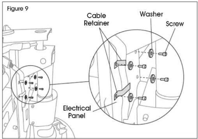
Figure 8- Replace previously removed screws, washers and guards back into place on electrical panel. (See Figure 9)

IMPORTANT! Ensure cable retainers are installed properly, securely holding cable.
text_image
Figure 9 Cable Retainer Washer Screw Electrical Panel-
Turn on unit and test lifting functions.
-
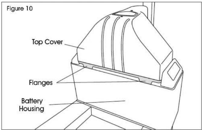
Replace top cover and secure with previously removed screws. (See Figure 10)

NOTE: Ensure flanges on front and back of top cover are correctly positioned and inside battery housing. (See Figure 10)