H-1679-MNBRD - Forklift Uline - Free user manual and instructions
Find the device manual for free H-1679-MNBRD Uline in PDF.

User questions about H-1679-MNBRD Uline
0 question about this device. Answer the ones you know or ask your own.
Ask a new question about this device
Download the instructions for your Forklift in PDF format for free! Find your manual H-1679-MNBRD - Uline and take your electronic device back in hand. On this page are published all the documents necessary for the use of your device. H-1679-MNBRD by Uline.
USER MANUAL H-1679-MNBRD Uline
ULINE H-1679-MNBRD MAINBOARD FOR PALLET TRUCK SCALES
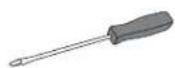
TOOLS NEEDED

text_image
Phillips Screwdriver Flathead Screwdriver 3 mm Flathead Screwdriver1-800-295-5510 uline.com
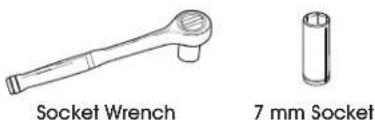
text_image
Socket Wrench 7 mm Socketnatural_image
Line drawing of a rectangular electronic device with multiple buttons and a cable, no text or symbols presentINSTRUCTIONS
MAINBOARD REMOVAL

IMPORTANT! Set all screws, nuts, caps and magnets aside after removal as they will be used for installation.
- Remove four screws connecting indicator faceplate to housing using a Phillips screwdriver. (See Figures 1-2)
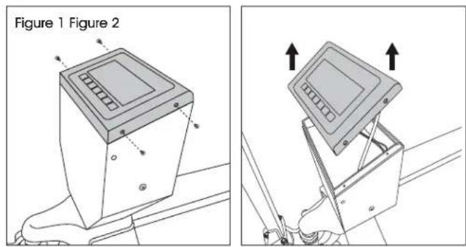
text_image
Figure 1 Figure 2- Turn faceplate over. Remove six nuts from mainboard using wrench with 7 mm socket. (See Figure 3)
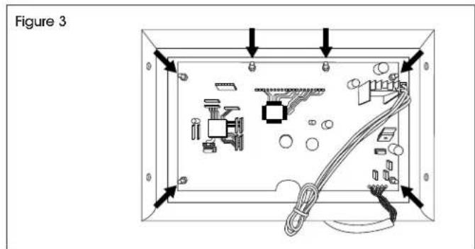
text_image
Figure 3-
Lift mainboard to remove from faceplate.
-
Remove red caps from front of mainboard.
- Disconnect white four-pin connector. Depress tab with flathead screwdriver to remove. (See Figures 4-5)
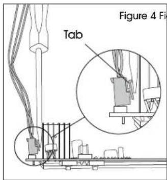
text_image
Figure 4 Fig Tab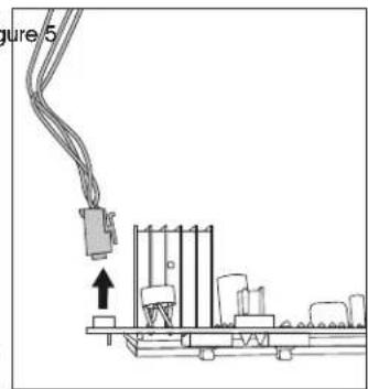
natural_image
Pure electrical circuit lines without any symbols- Remove screws on side of indicator housing (one on each side) with Phillips screwdriver to release front panel. (See Figure 6)
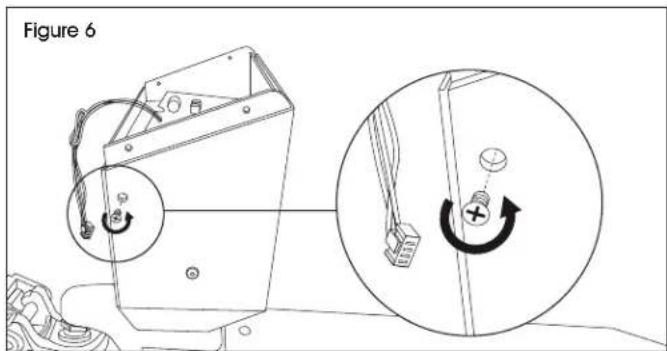
text_image
Figure 6INSTRUCTIONS CONTINUED
- Remove four screws from junction box faceplate with Phillips screwdriver. Remove faceplate. (See Figure 7)
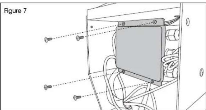
natural_image
Technical diagram of an electrical enclosure with screw placements and wiring, labeled Figure 7 (no text or symbols on the diagram itself)- Take photo of termination block wire pattern. Use a 3 mm flathead screwdriver to loosen screws holding colored wires. (See Figure 7)

IMPORTANT! Termination block screws only need one full turn to release wires.
- Gently remove colored wires from termination block. (See Figure 8)
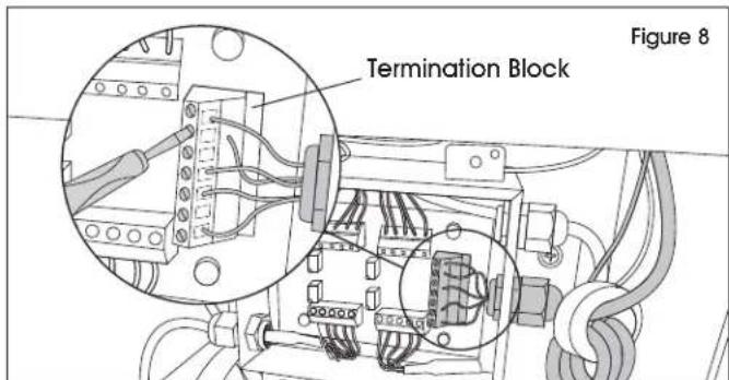
text_image
Termination Block Figure 8- Unscrew cord grip cap connecting main cable to junction box. (See Figure 9)
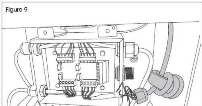
natural_image
Electrical wiring diagram inside a device labeled Figure 9, showing internal components and connections (no text or symbols beyond label)- Cut cable tie and unbundle main cable from circular magnet. Pull main cable through hole at top of indicator housing to remove.
INSTALLATION
- Insert main cable through hole at top of indicator housing. (See Figure 10)
- Wrap main cable around circular magnet three times. Slide cord grip cap onto end of main cable. (See Figure 11)
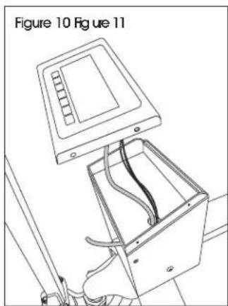
natural_image
Technical line drawing of an open electrical enclosure with internal wiring, labeled Figure 10 (no text or symbols on diagram)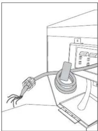
natural_image
Line drawing of a cable being inserted into an electrical enclosure (no text or symbols)- Feed main cable through cord grip on junction box. (See Figure 12)
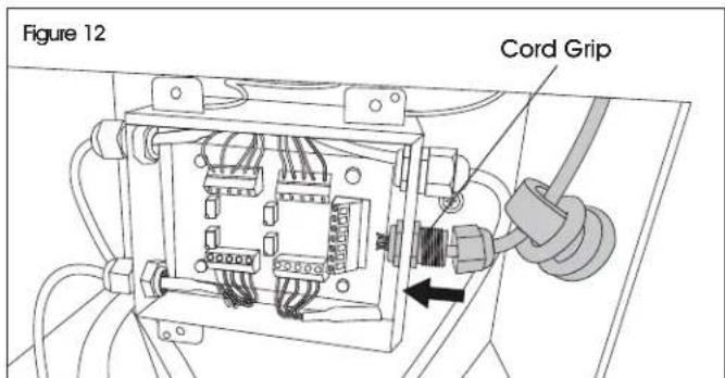
text_image
Figure 12 Cord GripINSTRUCTIONS CONTINUED
- Insert colored wires into termination block. Reference photo taken on step 8 of Mainboard Removal. Tighten screws using 3 mm screwdriver. (See Figure 13)

NOTE: Gently tug on wires to ensure proper installation.
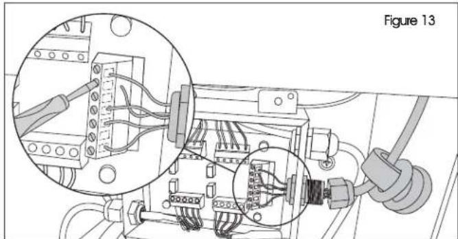
natural_image
Electrical wiring diagram showing connections between components in a circuit board (no text or symbols)- Screw on cord grip cap to secure main wire to junction box. (See Figure 14)
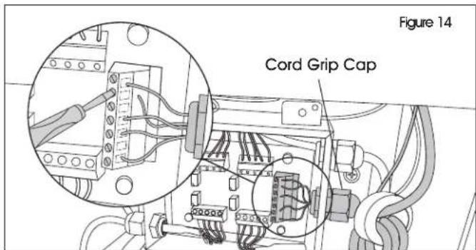
text_image
Figure 14 Cord Grip Cap- Replace and secure junction box faceplate using four previously removed screws and Phillips screwdriver. (See Figure 15)
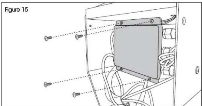
text_image
Figure 15- Replace front panel and secure with two previously removed Phillips head screws. (See Figure 16)
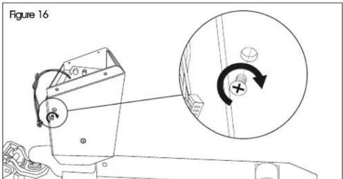
text_image
Figure 16- Reconnect four-pin connector to mainboard. (See Figure 17)
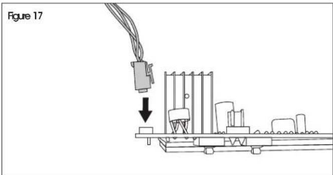
text_image
Figure 17-
Replace previously removed red caps onto mainboard.
-
Slide mainboard over posts on indicator faceplate. Secure using previously removed nuts and 7 mm socket wrench. (See Figure 18)

IMPORTANT! Check button and board functionality after tightening nuts. Buttons may not function if nuts are too tight or too loose.
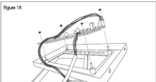
natural_image
Technical line drawing of a mechanical assembly with wires and components, labeled Figure 18 (no text or symbols on the diagram itself)INSTRUCTIONS CONTINUED
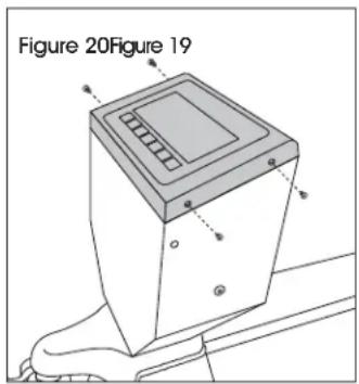
- Secure indicator faceplate to housing using four previously removed screws and Phillips screwdriver. (See Figures 19-20)
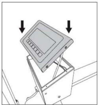
natural_image
Diagram of a device with an open lid and arrows indicating downward motion (no text or symbols)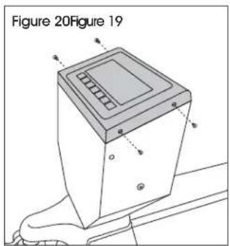
text_image
Figure 20Figure 19- Complete calibration. (See Calibration below)
CALIBRATION
ENTER TECHNICAL PARAMETER MODE

NOTE: Must use 10% of capacity to calibrate.
- Press ZERO and TARE keys at the same time. The display will show "F1 UNIT".
- Press TARE key until display shows "PROG" and press ZERO key to show "PN" on the display.
- Press in order M+, U and TARE keys to enter technical parameter setting mode.
- Press TARE key to select parameter, press ZERO key to enter value and U key to exit.
- It may be necessary to use TARE key to set a value or use M+ and PT keys to move the active digit.
CALIBRATION
- Enter Technical Parameter Setting mode (see Enter Technical Parameter Mode) until display shows "P1 rEF".
- Press the TARE key until display shows "P2 CAL". Press ZERO key to enter and press TARE key until display shows "CAL".
- Press ZERO key twice and display will show "UNLD". Remove all weight from the forks. After STABLE indicator is visible, press the ZERO key.
- The display shows the calibration weight value. Use the M+, PT and TARE keys to set the weight value.

NOTE: Use M+/PT keys to move active digit, use TARE key to change value. You can also press G/N to make value zero.
-
After weight is keyed, press ZERO key to enter. Display will show "LOAD".
-
Add calibration weight onto forks. After STABLE indicator is visible press ZERO key to enter.
Display returns to normal once calibration is successful. If an error message is shown, try the calibration steps again; a disturbance may have prevented a successful calibration. If the problem persists, please contact Uline Customer Service at 1-800-295-5510.
ULINE H-1679-MNBRD
PANEL PRINCIPAL PARA BÁSCULAS CON PATÍN HIDRÁULICO
natural_image
Line drawing of a rectangular electronic device with multiple ports and a cable, no text or symbols presentINSTRUCCIONES
natural_image
Line drawing of a cable being inserted into a device (no text or symbols visible)natural_image
Diagram of a device with an open lid and arrows indicating downward motion (no text or symbols)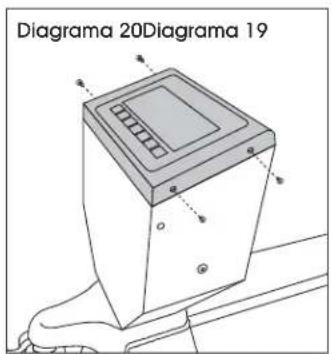
text_image
Diagrama 20Diagrama 19CALIBRACIÓN
INGRESAR AL MODO DE PARÁMETRO TÉCNICO

natural_image
Line drawing of a device with labeled buttons and cable, no text or symbols presentOUTILS REQUIS
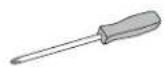
Tournevis cruciforme
natural_image
Diagram of a mechanical assembly with a connector and base components, no visible text or symbolsnatural_image
Technical diagram of an electrical enclosure with screw placements and wiring, labeled as Figure 7 (no text or symbols on the diagram itself)natural_image
Technical diagram of an electrical enclosure with wiring and connectors, labeled Figure 9 (no text or symbols on the diagram itself)text_image
Figure 10 Figure 11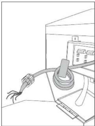
natural_image
Line drawing of a cable being inserted into a device (no text or symbols)natural_image
Electrical wiring diagram showing connections between components in a circuit (no text or symbols)text_image
Figure 15text_image
Figure 16text_image
Figure 17natural_image
Technical line drawing of a mechanical assembly with wires and components, labeled Figure 18 (no text or symbols on the diagram itself)INSTRUCTIONS SUITE
natural_image
Diagram of a device with an open lid and two arrows pointing downward (no text or symbols)