H-4121 - Forklift Uline - Free user manual and instructions
Find the device manual for free H-4121 Uline in PDF.


User questions about H-4121 Uline
0 question about this device. Answer the ones you know or ask your own.
Ask a new question about this device
Download the instructions for your Forklift in PDF format for free! Find your manual H-4121 - Uline and take your electronic device back in hand. On this page are published all the documents necessary for the use of your device. H-4121 by Uline.
USER MANUAL H-4121 Uline
natural_image
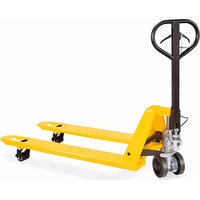
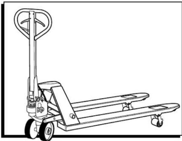
Line drawing of a manual pallet jack with handle and wheels (no text or symbols)TECHNICAL DATA
| CAPACITY 5,500 LBS. | |
| Max. Fork Height 7.5" | |
| Min. Fork Height | 3.0" |
| Fork Length | 48" |
| Width Overall Forks | 27" |
| Fork Wheel Diameter | 3" Polyurethane |
| Steering Wheel Diameter | 7" Rubber |
| Net Weight | 181 lbs. |
OPERATION

WARNING! Operator must read and understand instructions here and on truck prior to use.
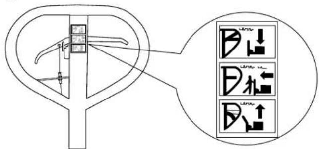
On the handle of the pallet truck, you will find the control lever which can be set in three positions. (See Figure 1)
Figure 1
text_image
Technical diagram showing a mechanical component with three directional control icons labeled P, P1, and P2.- LOWER = to lower the forks
- NEUTRAL = to move the load
- RAISE = to raise the forks
If the forks elevate while pumping in the NEUTRAL position, turn the setting screw clockwise until pumping the handle does not raise the forks and the NEUTRAL position functions correctly.
- If the forks descend while pumping in the NEUTRAL position, turn the setting screw counterclockwise until the forks do not lower.
- If the forks do not descend when the control lever is in the LOWER position, turn the setting screw clockwise until raising the control lever lowers the forks. Then check the NEUTRAL position as per steps 1 and 2.
- If the forks do not lift while pumping in the RAISE position, turn the setting screw counterclockwise until the forks elevate while pumping in the RAISED position. Then check the NEUTRAL and LOWER position as per steps 1, 2 and 3.

NOTE: When viewing the truck from the handle side, the setting screw is located on the right side of the pump above the right wheel. The truck will lower faster or slower depending on how far in or out the screw is adjusted.
MAINTENANCE
HOW TO EXPEL AIR FROM THE PUMP UNIT
Air may enter the unit over time or when the seals are replaced. To expel the air, lift the control lever to the LOWER position and move the handle up and down several times.
DAILY CHECK AND MAINTENANCE
Daily checks of the pallet truck can limit wear and tear on the unit. Pay special attention to the wheels, the axles, the handle, the forks and lift and lower controls.
LUBRICATION
Use motor oil or grease to lubricate all moveable parts.
SAFETY
For safe operation of the Pallet Truck With Hand Brake, please read all warning signs and instructions here and on the pallet truck prior to use.
- Do not operate the pallet truck unless you are familiar with it and have been trained and authorized to do so.
- Do not use the truck on sloping ground.
- Never place any part of your body in the lifting mechanism or under the forks or load. Do not carry passengers.
-
We advise that operators wear gloves and safety shoes.
-
Do not handle unstable or loosely stacked loads.
- Do not overload the truck.
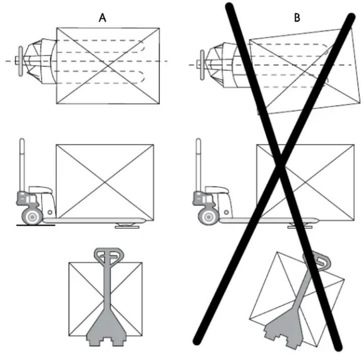
- Always center loads on the forks, not at the end of the forks. (See Figure 2)
- The capacity of the truck assumes an evenly distributed load with the center of the load being at the halfway point of the length of the forks.
- Make sure that length of the forks matches the length of the pallet load.
- Lower the forks to lowest height when the truck is not being used.
Figure 2
HAND BRAKE INSTRUCTIONS
BRAKING
- Locate brake lever on left side of the handle. Pull brake lever up to apply brake. (See Figure 3)
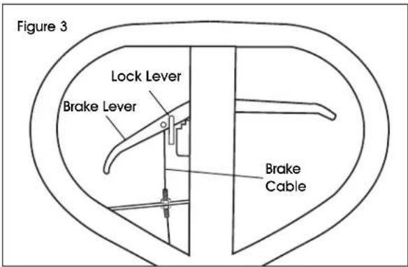
text_image
Figure 3 Lock Lever Brake Lever Brake Cable- Let go of brake lever to release brake.
- To engage parking brake, pull brake lever up to apply brake. (See Figure 4)
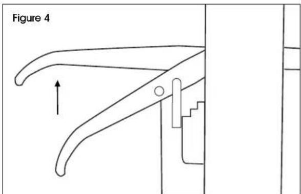
text_image
Figure 4- Continue pulling brake lever and slide lock lever into position. (See Figure 5)
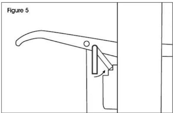
text_image
Figure 5- Release brake lever. Brake will remain engaged when truck is not in use.
- To release parking brake, pull brake lever up and remove lock lever from position. (See Figure 6)
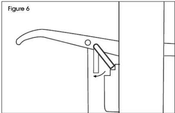
text_image
Figure 6BRAKE ADJUSTMENT
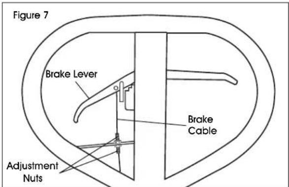
- Locate the adjustment nuts on the left side of handle. (See Figure 7)
text_image
Figure 7 Brake Lever Brake Cable Adjustment Nuts- Loosen top and bottom nuts to release tension in brake cable.
- Tighten nuts individually, pulling brake lever up as you go to test brake.
- Adjust nuts until desired tension and brake power is achieved.
HAND BRAKE INSTRUCTIONS CONTINUED
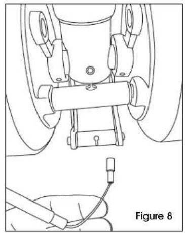
- Insert end of brake cable into bottom hinge pin. (See Figure 8-9)
natural_image
Technical line drawing of a mechanical assembly with a labeled component (Figure 8), showing no text or symbols beyond the label.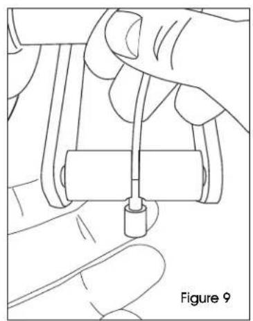
natural_image
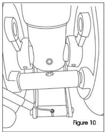
Line drawing of a hand holding a cable with a small component, labeled 'Figure 9' (no text or symbols on the diagram itself)- Pull tight until bottom cable knob is firmly in place. (See Figure 10)
natural_image
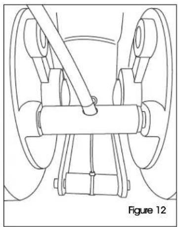
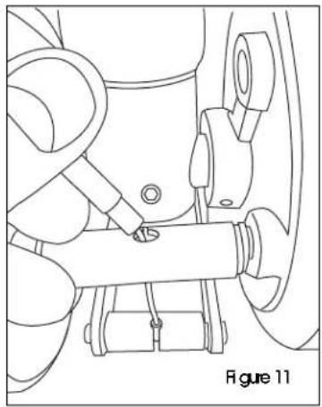
Technical line drawing of a mechanical assembly with no visible text or symbols- Insert top of brake cable into top holding pin and push into place. (See Figures 11-12)
natural_image
Technical line drawing of a mechanical assembly with no visible text or symbols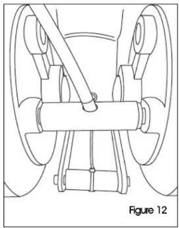
natural_image
Technical line drawing of a mechanical assembly with no visible text or symbolsTROUBLESHOOTING
| OPERATING ISSUE CAUSES RECOMMENDATIONS | ||
| The forks do not raise. The setting | screw is not in the correct position.Air in the hydraulic oil. | Adjust the setting screw.(See Operation)Expel the air. (See Maintenance) |
| The forks do not descend. The rod and/or cylinder are deformed resulting from a seriously unbalanced load.A part has been broken or deformed resulting from an unbalanced load.The setting screw is not in the correct position. | Replace the rod and/or cylinder.Repair or replace component.Adjust the setting screw.(See Operation) | |
| Leaks. Seals worn out or damaged. | Some parts may be cracked or worn out. | Replace seals with new ones.Replace pump. |
| The forks descend without being lowered. | Air in the hydraulic oil.Components worn out or damaged.The setting screw is not in the correct position. | Expel the air. (See Maintenance)Replace components.Adjust the setting screw.(See Operation) |
| Brake not working. | Cable sheath is improperly mounted. | Ensure cable sheath is properly mounted between pump and wheels. |

NOTE: Do not attempt to repair the pallet truck unless you are trained and authorized to do so.
ULAN2
PATÍN HIDRÁULICO CON FRENO DE MANO
800-295-5510
uline.mx
natural_image
Line drawing of a manual pallet jack with handle and wheels (no text or symbols)INFORMACIÓN TÉCNICA
text_image
Technical diagram showing a mechanical component with three directional control icons labeled P, L, and R.natural_image
Technical line drawing of a mechanical assembly with a labeled component (Diagrama 8), showing no text or symbols beyond the label.natural_image
Technical line drawing of a mechanical assembly with no visible text or symbols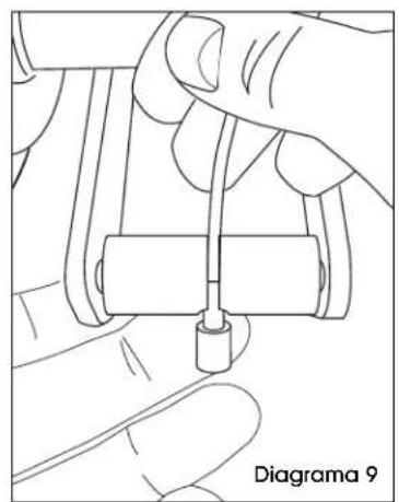
natural_image
Hand holding a small cylindrical object with a connecting rod, no visible text or symbols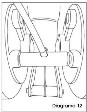
natural_image
Technical line drawing of a mechanical assembly with no visible text or symbolsnatural_image
Technical line drawing of a mechanical assembly with no visible text or symbolsnatural_image
Line drawing of a manual pallet jack with handle and wheels (no text or symbols)DONNÉES TECHNIQUES
text_image
Technical diagram showing a mechanical component with three directional control icons labeled P, B, and D.natural_image
Technical line drawing of a mechanical assembly with a close-up view of a component labeled Figure 8 (no text or symbols on the diagram itself)natural_image
Technical line drawing of a mechanical assembly with no visible text or symbols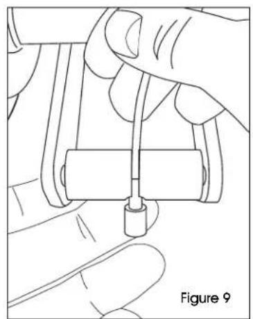
natural_image
Line drawing of a hand holding a small cylindrical object with a handle, labeled 'Figure 9' (no text or symbols on the diagram itself)