
Touchless K-10953 - Faucet KOHLER - Free user manual and instructions
Find the device manual for free Touchless K-10953 KOHLER in PDF.

| Product type | Touchless electronic faucet |
| Brand | Kohler |
| Model | Touchless K-10953 |
| Power supply | 6 V DC (lithium 2CR5 battery or AC adapter) |
| Power | 1 W |
| Sensor type | Passive infrared (sensor eyes) |
| Minimum water pressure | 20 psi (137 kPa) |
| Mounting hole diameter | 1-1/16\" (2.7 cm) to 2-1/2\" (6.4 cm) |
| Mounting configuration | Single or double threaded rod |
| Adjustable maximum hot water temperature | Up to 105°F (41°C) by default, adjustable by splines (10°F per notch) |
| Filters included | Yes, filter assembly on each stop valve (20 microns recommended) |
| Recommended battery | Lithium 2CR5 6 V (not supplied by Kohler) |
| Main material | Chrome-plated metal and plastic (spout, body) |
| Dimensions (approximate) | Height: approximately 15 cm, Depth: approximately 20 cm (swivel spout) |
| Weight (approximate) | 1.5 kg (with battery) |
| Main functions | Automatic motion activation, automatic shut-off, limited temperature adjustment |
| Maintenance and cleaning | Clean the sensors with a soft, damp cloth; clean the filters and aerator periodically |
| Safety | Adjustable temperature stop to prevent burns; automatic shut-off after use |
| Spare parts and repairability | Sensor, solenoid, diaphragm, O-rings, filters, aerator, battery, AC adapter |
| General information | Follow local codes; shut off water before installation; use a thermometer for adjustment |
Frequently Asked Questions - Touchless K-10953 KOHLER
User questions about Touchless K-10953 KOHLER
0 question about this device. Answer the ones you know or ask your own.
Ask a new question about this device
Download the instructions for your Faucet in PDF format for free! Find your manual Touchless K-10953 - KOHLER and take your electronic device back in hand. On this page are published all the documents necessary for the use of your device. Touchless K-10953 by KOHLER.
USER MANUAL Touchless K-10953 KOHLER
K-10950, K-10951 K-10952, K-10953
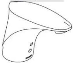
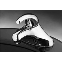
natural_image
Line drawing of a showerhead with handle and outlet (no text or symbols)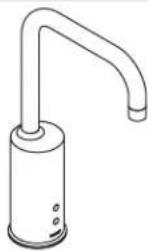
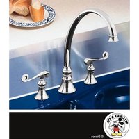
K-10954, K-10955
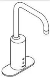
natural_image
Line drawing of a hand washing machine (no text or symbols)Mproduct numbers are for Mexico (i.e. K-12345M)
Thank You For Choosing Kohler Company
We appreciate your commitment to Kohler quality. Please take a few minutes to review this manual before you start installation. If you encounter any installation or performance problems, please don't hesitate to contact us. Our phone numbers and website are listed on the back cover. Thanks again for choosing Kohler Company.
Tools and Materials

Before You Begin
NOTE: The faucet shown in the following installation procedures may differ from your actual product. However the installation steps apply to all faucets packed with this guide.
□ Observe all local plumbing and building codes.
□ Shut off the main water supply.
□ Carefully inspect the waste and supply tubing for any sign of damage.
☐ The faucet will not function properly with lavatories that have a lip height of more than 1"(2.5 cm).
☐ For this faucet to function properly, install the faucet so the sensor points directly toward the user.
Before installation, unpack the new faucet and inspect it for damage. Remove and dispose of the protective tape covering the sensor eyes on the front of the faucet body.
☐ Return the faucet to the carton until you are ready to install it.
☐ For new installations, install the faucet before installing the lavatory.
Before You Begin (cont.)
☐ The faucet is rated at 6 V D C 1 W a n d i s operated by a 6 V D C battery or an optional AC power supply.
NOTE: In areas where the water has a high particulate level, install a 20-micron water filter in the water supply line.
☐ Kohler Co. reserves the right to make revisions in the design of faucets without notice, as specified in the Price Book.
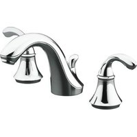
natural_image
Line drawing of a mechanical tool dispensing liquid into a square basin (no text or symbols)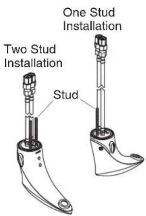
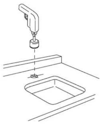
1. Prepare for Installation
NOTE: When installing this faucet to a 1-1/16" (2.7 cm) to 1-1/4" (3.2 cm) diameter hole, a single stud configuration should be employed. When installing this faucet to a 1-1/4"(3.2 cm) to 2-1/2" (6.4 cm) diameter hole, a two stud configuration should be employed.
NOTE: The faucet comes configured for a two threaded stud installation.
☐ For new installations, drill a 2-1/2"(6.4 cm) diameter mounting hole if there is no existing installation hole.
☐ If installing the faucet on an existing deck, confirm the mounting hole is a minimum diameter of 1-1/16"(2.7 cm).
☐ If the installation requires a one stud configuration, remove both studs using a pliers. Take care not to damage the threads. Reinstall the stud in the single stud mounting hole behind the flex hoses.
☐ If a single supply of tempered water will be used, remove the flexible hose from the hot side of the faucet and replace it with the provided plug.
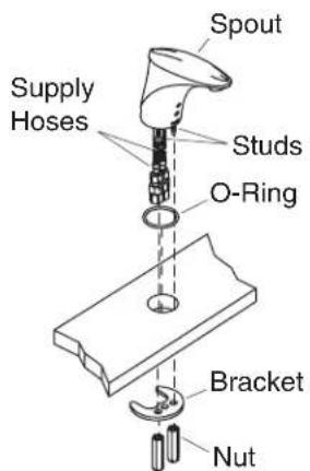
Without Escutcheon
With Escutcheon
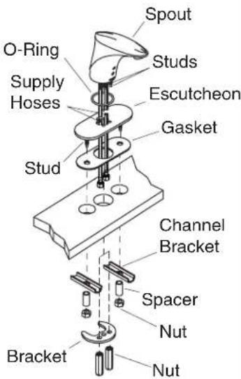
2. Faucet Installation
☐ Slide the O-ring over the flex hoses and studs, and attach it to the groove in the base of the spout.
☐ Ifinstallingtheoptionalescutcheon: Thread the supplied studs into the holes in the bottom of the escutcheon. Carefully slide the escutcheon and gasket over the flex hoses and stud(s) up to the base of the spout.
□ Run the flex hose and studs through the mounting hole from above.
☐ Slide the bracket onto the stud(s). If a single stud configuration is being used, slide the stud through the middle hole in the bracket.
☐ Thread the supplied nut(s) onto the faucet stud(s).
☐ Forescutcheoninstallations: Slide the channel brackets and spacers onto the escutcheon studs. Thread the nuts onto the studs to secure.
□ Tighten all nuts securely. Do not overtighten.
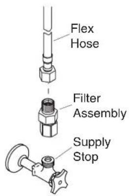
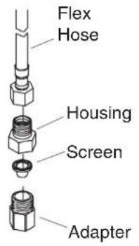
3. Attach the Filter Assembly
☐ Turn on the water and flush the water through the supply stops into a bucket.
□ Turn off the water.
☐ Thread a filter assembly onto each supply stop.
☐ Thread a flex hose onto the other end of each filter assembly.
☐ Turn on the water and flush the faucet by activating it.
NOTE: For optimum performance, clean your filters periodically. Refer to the Maintenance Guide.
4. Optional Temperature Limiting Adjustment

CAUTION: Riskofpersonalinjury. Scalding may result if the limit stop is not reinstalled properly.
NOTE: The water temperature does not need to be adjusted if the water temperature is below 105^ F ( 41^ C).
NOTE: Use a thermometer rated for 120^ F ( 49^ C) or greater.
NOTE: When using a tempered water supply, install the vandal-resistant plug button.
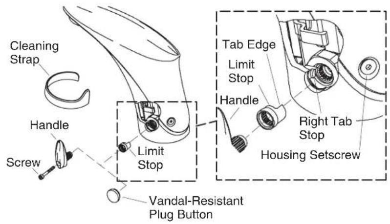
Adjust the Water Temperature Limit – Handle Installations
☐ Turn on the water and adjust to the full hot position by turning the handle toward the back of the faucet until it stops.
☐ Determine the temperature using a thermometer. If the temperature exceeds 105^ F ( 41^ C), complete the following steps.
□ Turn the handle until vertical.
□ Attach the cleaning strap over the sensor.
☐ Remove the handle screw using the supplied 2.5 mm hex wrench.
□ Remove the handle and the limit stop.
□ Remove the limit stop from the handle splines.
Optional Temperature Limiting Adjustment (cont.)
☐ Rotate and reposition the limit stop on the handle splines. Rotating the limit stop clockwise toward the back of the faucet will decrease the maximum temperature limit. Each spline represents approximately 10^ F ( 5^ C) change in temperature.
☐ Reinstall the handle vertically with the limit stop in place. Do not secure the handle with the screw at this time.
☐ Turn the handle to full hot and check the water temperature.
☐ Repeat the above procedures until the desired temperature is reached.
□ Secure the handle assembly with the screw.
□ Remove the cleaning strap and turn on the water.
Adjust the Water Temperature Limit – Vandal Resistant Installations
NOTE: If you install the vandal-resistant plug button, save the limit stop and handle to adjust the water temperature at a later date.
☐ Using the handle, adjust the water to the desired temperature.
☐ Remove the handle screw using the supplied 2.5 mm hex wrench.
☐ Position the vandal-resistant plug button and firmly press into place.
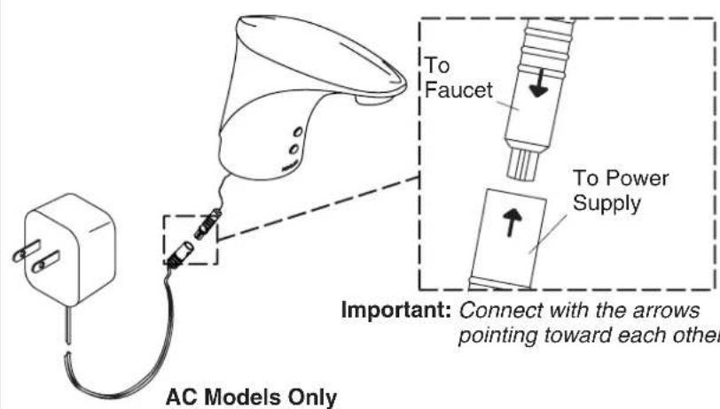
5. Installation Checkout
IMPORTANT!Connect the connectors with the arrows pointing directly toward each other.
☐ If installing the AC version, connect the valve cord to the AC power supply.
□ Plug the power cord into the appropriate outlet.
□ Use the aerator key provided to remove the aerator. Clean any debris from the aerator screen and reinstall.
□ Check for leaks with and without the water running.
6. Troubleshooting
Troubleshooting Table
| SymptomsProbable | CausesRecommended | Action |
| 1.No water flow (DC). | A.There is a loose connection. | A.Remove the spout and check the connection from the battery to the solenoid and from the solenoid to the sensor. Make sure that the connector arrows are aligned and that the connection is secure. Refer totheMaintenanceGuide. |
Kohler Co. 9 1025498-2-E
| Troubleshooting (cont.) | ||
| SymptomsProbable | CausesRecommended | Action |
| B.The wires are pinched or damaged. | B.Remove the spout and verify that the wires are tucked inside the spout before reassembling. If the wires are cut or damaged, order a new solenoid or sensor assembly. | |
| C.There is water leakage on electrical components or connectors. | C.Remove the spout and check for corrosion on the connections between the battery to solenoid and the solenoid to sensor. If possible, clean the terminals. If unable to repair the connection, order a new sensor assembly or solenoid assembly, as required. Inspect the O-ring on the valve for cuts, debris, etc. If the O-ring is damaged, order a new O-ring. The origin of the leak must be investigated and repaired. Refertothe MaintenanceGuide. | |
| D.The battery life has expired. | D.Replace the battery. Refer totheMaintenanceGuide. | |
| 2.No water flow (AC). | A.The AC unit is not plugged in. | A.Plug the AC wall brick firmly into a working outlet. |
| B.The ground fault breaker is tripped. | B.Check that the breaker for the circuit used by the faucet is on. | |
| C.There is a loose connection. | C.Remove the spout and check the connection from the AC unit to the solenoid and from the solenoid to sensor. Make sure that the connector arrows are aligned and that the connection is secure. Refer totheMaintenanceGuide. | |
1025498-2-E 10 Kohler Co.
| Troubleshooting (cont.) | ||
| SymptomsProbable | CausesRecommended | Action |
| D.The wires are pinched or damaged. | D.Remove the spout and verify that the wires are tucked inside the spout before reassembling. If wires are cut or damaged, order new solenoid or sensor assembly. | |
| E.There is water leakage on electrical components or connectors. | E.Remove the spout and check for corrosion on connections between AC unit to solenoid and the solenoid to sensor. If possible, clean the terminals. If you are unable to repair the connection, order a new battery assembly or sensor assembly, as required. The origin of the leak must be investigated and repaired. RefertotheMaintenance Guide. | |
| F.The AC unit does not work. | F.Measure the voltage of the unit. The voltage should measure 6 volts. If there is no power or low power is detected, order a new unit. | |
| 3.No water flow (Either AC or DC). | A.Sensor eyes are dirty. | A.Wipe the sensor eyes with a damp soft cloth. Wipe dry with a dry soft cloth. |
| B.Water not turned on. | B.Verify that the water supply is turned on and that pressure is at least 20 psi (137 kPa). | |
| C.Incorrect installation. | C.Verify that the faucet is mounted flat to the deck surface and that the sensor eyes are aligned to the user area. Ensure that the sensor eyes are above the rim of the lavatory. Refer to the installation instructions. | |
| D.The filter(s) are plugged. | D.Clean the Filters. Referto theMaintenanceGuide. | |
Kohler Co. 11 1025498-2-E
| Troubleshooting (cont.) | ||
| SymptomsProbable | CausesRecommended | Action |
| E.The aerator is plugged. | E.Remove the aerator and clean it. For calcium/mineral deposits, soak the aerator plastic insert in a 50:50 mixture of vinegar and water. Soak only the insert and no other components. Referto theMaintenanceGuide. | |
| FSensor eyes are scratched. | FReplace the sensor assembly. Refertothe MaintenanceGuide. | |
| G.The bleed hole in the diaphragm is plugged or the plunger is stuck. | G.Clean the valve cover and diaphragm assembly. RefertotheMaintenanceGuide. | |
| 4.Low flow (either AC or DC). | A.Supply pressure is low. | A.Check any filtration systems for blockage. Check incoming water pressure. Pressure should be at least 20 psi (137 kPa). |
| B.Filters are plugged. | B.Clean the Filters. Referto theMaintenanceGuide. | |
| C.Aerator is plugged. | C.Remove the aerator and clean it. For calcium/mineral deposits, soak the aerator plastic insert in a 50:50 mixture of vinegar and water. Soak only the insert and no other components. | |
| 5.Constant water flow (DC). | A.Battery life expired. | A.Remove spout and replace battery. Refertothe MaintenanceGuide. |
| 6.Constant water flow (AC). | A.The power source is unstable, off, or the circuit is blown. | A.Once the power is stable, unplug the unit and plug back into wall. |
| 7.Constant water flow (Either AC or DC). | A.The diaphragm seal dirty or damaged. | A.Clean the valve cover and diaphragm assembly. Referto theMaintenanceGuide. |
1025498-2-E 12 Kohler Co.
| Troubleshooting (cont.) | ||
| SymptomsProbable | CausesRecommended | Action |
| B.The solenoid is plugged. | B.Remove the spout and solenoid. Check the solenoid holes for debris. RefertotheMaintenance Guide. | |
| C.The solenoid does not work. | C.Remove the spout and solenoid. Replace the solenoid. Refertothe Maintenance Guide. | |
| D.The filter(s) are plugged. | D.Clean the Filters. Referto theMaintenanceGuide. | |
| 8.Sporadic water flow. | A.The faucet is installed at wrong angle to deck or misaligned with user area. | A.Verify that the faucet is mounted flat to the deck surface and that the sensor eyes are aligned to the user area. Ensure that the faucet is installed in a position that is above the rim of the lavatory. |
| B.The wires are pinched or damaged. | B.Remove the spout and verify that the wires are tucked inside the spout before reassembling. | |
| 9.Water is dripping on deck. | A.The valve O-ring is missing, cut, or damaged. | A.Order a new O-ring for the valve and install. Referto theMaintenanceGuide. |
| 10.Sensor flashes once approximately every 8 seconds. The product continues to operate. | A.The battery power is low. | A.Replace the battery. The product may continue to operate for several days with low battery power. The product requires a 2CR5 6 V lithium battery. This item is not available from Kohler Co. but can be purchased at a local retail store. |
| 11.Sensor flashes once approximately every 2 seconds. The product does not operate. | A.The battery power is insufficient to allow the product to operate. | A.Replace the battery. The product requires a 2CR5 6 V lithium battery. This item is not available from Kohler Co. but can be purchased at a local retail store. |
Kohler Co. 13 1025498-2-E
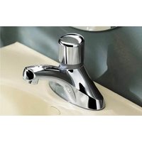
natural_image
Technical line drawing of a mechanical assembly with a tool above a square sink (no text or symbols)
natural_image
Line drawing of a mechanical tool dispensing liquid into a square basin (no text or symbols)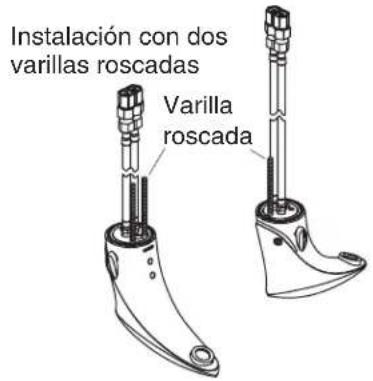
- Thank You For Choosing Kohler Company
- Tools and Materials
- Before You Begin
- Before You Begin (cont.)
- Prepare for Installation
- Faucet Installation
- Attach the Filter Assembly
- Optional Temperature Limiting Adjustment
- Adjust the Water Temperature Limit – Handle Installations
- Optional Temperature Limiting Adjustment (cont.)
- Adjust the Water Temperature Limit – Vandal Resistant Installations
- Installation Checkout
- Troubleshooting
Brand : KOHLER
Model : Touchless K-10953
Category : Faucet