
DXCM024-0434 - Compressor DEWALT - Free user manual and instructions
Find the device manual for free DXCM024-0434 DEWALT in PDF.

| Product Type | Air Hose Reel |
| Brand | DeWalt |
| Model | DXCM024-0345 |
| Net Weight | 9.5 kg (20.9 lbs) |
| Air Inlet | 1/4" NPT female (6.3 mm) |
| Hose Type | Hybrid polymer |
| Hose Size | 3/8" (9.5 mm) diameter |
| Hose Length | 15.2 m (50 ft) |
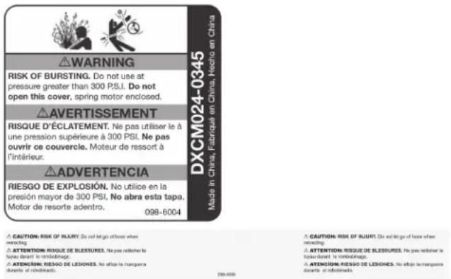
| Maximum Operating Pressure | 300 PSI (2,068 kPa) |
| Air Outlet | 1/4" NPT (6.3 mm) at hose end |
| Lead-in Hose | 3/8" (9.5 mm) x 1.2 m (4 ft) with swivel fitting |
| Housing Material | Polymer |
| Mounting Type | Wall mount bracket with removable pin |
| Locking Mechanism | Ratchet lock for length retention |
| Adjustable Ball Stop | Yes, to limit hose extension |
| Bend Limiter | Yes, to protect hose |
| Intended Use | Compressed air supply for pneumatic tools |
| Maintenance | Check for leaks regularly, clean with a dry cloth |
| Safety | Do not exceed 300 PSI, wear safety glasses and hearing protection |
| Warranty | 1 year limited (free repair or replacement) |
| Customer Service | 1-800-4-DEWALT (1-800-433-9258) |
Frequently Asked Questions - DXCM024-0434 DEWALT
User questions about DXCM024-0434 DEWALT
0 question about this device. Answer the ones you know or ask your own.
Ask a new question about this device
Download the instructions for your Compressor in PDF format for free! Find your manual DXCM024-0434 - DEWALT and take your electronic device back in hand. On this page are published all the documents necessary for the use of your device. DXCM024-0434 by DEWALT.
USER MANUAL DXCM024-0434 DEWALT
If you have questions or comments, contact us. Pour toute question ou tout commentaire, nous contacter. Si Tiene dudas o comentarios, contactedenos.
1-800-4-DEWALT · www.dewalt.com
INSTRUCTION MANUAL GUIDE D'UTILISATION
MANUAL DE INSTRUCCIONES
INSTRUCTIVO DE OPERACION, CENTROS DE SERVICIO Y POLIZA DE GARANTIA. ADVERTENCIA: LÉASE ESTE INSTRUCTIVO ANTES DE USAR EL PRODUCTO.
DEWALT®
DXCM024-0345
3/8" X 50' Enclosed Hybrid Polymer Hose Reel
Carrete Cerrado Con Manguera De Polimero Hibrido - 9,5 mm x 15,2 m
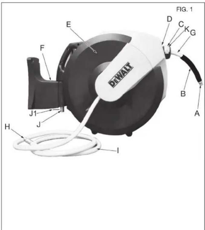
DXCM024-0345 Air Hose Reel
A. Air line outlet (to air tool/accessory)
B. Hose bend restrictor
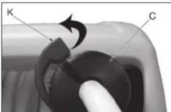
C. Ball stop
D. Hose guide
E. Hose reel enclosure
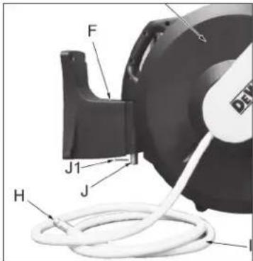
F. Mounting bracket
G. Air hose
H. Air line inlet
I. Lead-in air hose (attached to hose reel)
J. Hose reel mounting pin
J1. Cotter pin
K. Ratchet lock
Specifications
| MODEL DXCM024-0345 | |
| NET WEIGHT 20.9 lbs. (9,5 kg) | |
| AIR INLET SIZE 1/4" NPT (6,3 mm) | (female/hembra/femelle) |
| HOSE TYPE Hybrid polymer | |
| AIR HOSE SIZE 3/8" (9,5 mm) | |
| MAX. AIR PRESSURE 300 PSI (2,068 kPa) | |
| AIR HOSE LENGTH | 50' (15,2 m) |
Definitions: Safety Guidelines
The definitions below describe the level of severity for each signal word. Please read the manual and pay attention to these symbols.
DANGER: Indicates an imminently hazardous situation which, if not avoided, will result in death or serious injury.
WARNING: Indicates a potentially hazardous situation which, if not avoided, could result in death or serious injury. CAUTION: Indicates a potentially hazardous situation which, if not avoided, may result in minor or moderate injury.
CAUTION: Used without the safety alert symbol indicates a potentially hazardous situation which, if not avoided, may result in property damage.
IF YOU HAVE ANY QUESTIONS OR COMMENTS ABOUT THIS OR ANY DEWALT TOOL, CALL US TOLL FREE AT: 1-800-4-DEWALT (1-800-433-9258)
Important Safety Instructions
WARNING: Some dust created by power sanding, sawing, grinding, drilling, and other construction activities contains chemicals known to the State of California to cause cancer, birth defects or other reproductive harm. Some example of these chemicals are:
- Lead from lead-based paints
- Crystalline silica from bricks and cement and other masonry products
- Arsenic and chromium from chemically-treated lumber
Your risk from these exposures varies, depending on how often you do this type of work. To reduce your exposure to these chemicals: work in a well ventilated area, and work with approved safety equipment, al ways wear OSHA/MSHA/NIOSH approved, properly fitting face mask or res pi ra tor when us ing such tools. When using air tools, basic safety precautions should always be followed to reduce the risk of personal injury.
WARNING: This product contains chemicals, known to the State of California to cause cancer, and birth defects or other reproductive harm. Wash hands after handling.
SAVE THESE INSTRUCTIONS
WARNING:

Improper operation or maintenance of this product could result in serious injury and property damage. Read and understand all warnings and operating instructions before using this equipment. When using air tools, basic safety precautions should always be followed to reduce the risk of personal injury.
WARNING:

Read and understand this instruction manual and tool labels before installing, operating or servicing this tool. Keep these instructions in a safe accessible place.

Operators and others in work area must wear ANSI Z87.1 CAN/CSA Z94.3 approved safety glasses with side shields.

Operators and others in work area must wear ear protection.
WARNING:
- Do Not Use oxygen or reactive gases; explosion may occur.
- Do Not Exceed air pressure of 300 PSI.
- Read all manuals included with this product carefully. Be thoroughly familiar with the controls and the proper use of the equipment.
- Do not exceed any pressure rating of any component in the system.
- Disconnect the air tool from air supply before changing tools or attachments and during non-operation.
Always use attachments designed for use with air powered tools. - Do not use damaged or worn attachments.
- Check air hoses for weak or worn condition before each use. Make sure all connections are secure.
- Keep all nuts, bolts and screws tight and ensure equipment is in safe working condition.

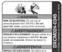
DANGER: RISK OF EXPLOSION OR FIRE CAN HAPPEN HOW TO PREVENT IT
-
Exceeding the maximum pressure rating of tools accessories could cause an explosion resulting in serious injury.
-
Use compressed air regulated to a maximum pressure at or below the rated pressure of any attachments.

DANGER: RISK TO BREATHING (ASPHYXIACTION)
WHAT CAN HAPPEN HOW TO PREVENT IT
- Abrasive tools, such as grinders, sanders, and cut-off tools generate dust and abrasive materials which can be harmful to human lungs and respiratory system.
Always wear MSHA/NIOSH approved, properly fitting face mask or respirator when using such tools.

CAUTION: RISK FROM NOISE
WHAT CAN HAPPEN HOW TO PREVENT IT
- Long term exposure to noise produced from the operation of air tools can lead to permanent hearing loss.
Always wear ANSI (S3.19) hearing protection.

WARNING: RISK OF INJURY
WHAT CAN HAPPEN HOW TO PREVENT IT
Air tools can propel loose objects or other materials throughout the work area.
- Keep work area clean and free of clutter. Keep children and others away from work area during operation of the tool.
- Keep work area well lit.
- Use compressed air regulated to a maximum pressure at or below the rated pressure of any attachments.
- Never use oxygen, carbon dioxide or other bottled gases as a power source for air tools.
- Protect air lines from damage or puncture.
- Check air hoses for weak or worn condition before each use. Make sure all connections are secure.

WARNING: RISK FROM FLYING OBJECTS
WHAT CAN HAPPEN HOW TO PREVENT IT
Air powered equipment and power tools are capable of propelling materials such as metal chips, saw dust, and other debris at high speed, which could result in serious eye injury.
- Compressed air can be hazardous. The air stream can cause injury to soft tissue areas such as eyes, ears, etc. Particles or objects propelled by the stream can cause injury.
Always wear ANSI Z87.1 CAN/ CSA Z94.3 approved safety glasses with side shields.
- Never leave operating tool unattended. Disconnect air hose when tool is not in use.
- For additional protection use an approved face shield in addition to safety glasses.
SAVE THESE INSTRUCTIONS FOR FUTURE USE
AIR LINE INLET
The air line inlet (H) is 1/4 NPT and is located on the on the side of the hose reel.
MOUNTING BRACKET
The poly mounting bracket (F) has a hose reel mounting pin (J) that is removable so it can be easily mounted on a wall.
LEAD-IN AIR HOSE
The lead-in hose (I) is 3/8'' × 4' long and has a swivel connection on one end to prevent the hose
from twisting or kinking. This comes attached to the hose reel.
AIR LINE OUTLET
The air line outlet (A) is 1 / 4 NPT and is located on the end of the air hose (G) for convenient connection to air accessories or tools.
AIR HOSE
The air hose (G) is 3 / 8'' × 50' and is attached to the hose reel.
BALL STOP
The ball stop (C) is adjustable and allows the desired length of hose to be permanently set
HOSE BEND RESTRICTOR
The hose restrictor (B) reduces bending stress near the fitting,
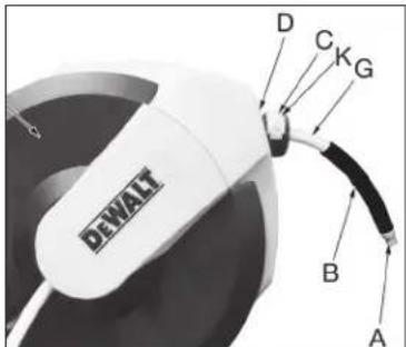
preventing damage and extending the life of the air hose (G).
INSTALLATION
- Choose a mounting location that is free of electrical wiring or other obstructions and is sturdy enough to support the weight of the hose reel and hose as well as the force used to extend and retract it. The hose reel is to be mounted on a wall. (see Figure 2).
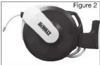
- Use the included mounting template to mark and drill the hole locations.
3 Mount the hose reel bracket in the desired location. Purchase the appropriate fasteners at your local hardware store.
-
Slide the hose reel mounting pin (J) into the bracket (F) and secure with cotter pin (J1) through the hole in (J).
-
If an adjustment needs to made to increase or decrease the length of hose that is outside of the hose reel, pull out the hose slowly until it latches at the desired length. Pull up on the ratchet lock (K) and slide the ball stop (C) to a position close to the hose guide (D). Lock in place by clo
WARNING:
1) Make sure the hose reel is secure before each use.
2) Never connect to an air source that is greater than 300 PSI.
3) Inspect the air hose before each use to make sure there are no leaks.
4) Do not wrap the hose around any parts of the body.
COMPRESSOR HOOK-UP
The hose reel includes a 3/8'' × 4' lead-in hose that is attached to the hose reel for hooking up the hose reel to your air source. Thread and connect the open end into your air source. Attach air tool or accessory to the air line outlet of the air hose on the hose reel.
OPERATION
Check the operation of the reel by slowly pulling out the hose. You will hear a clicking noise.
LOCKING HOSE REEL
Pull out the hose slowly until the desire length of hose is reached, allow it to retract after hearing a series of clicks.
UNLOCKING HOSE REEL
Pull out the hose slowly until the clicking noise stops, allow it to retract until the ball stop rests against the hose guide. DO NOT LET GO OF THE HOSE!
WARNING: Risk of Injury. Do not let go of the hose when retracting.
WARNING: Always disconnect air tool or accessory attached to the hose reel from air supply before making any adjustments and changing accessories.
ADJUSTING RECOIL TENSION
Occasional spring adjustment may be necessary when: The spring has relaxed over time. The hose has been replaced.
Large temperature changes have occurred.
CAUTION: Only adjust the spring when the hose is fully rewound. Do not overtighten the spring.
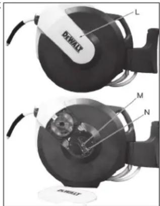
- Remove the cover (L) on the right side of the hose reel by squeezing the sides and pulling out the bottom first.
2 Pull out the crank handle (M). - Turn the crank (N) clockwise to increase tension, counterclockwise to reduce tension.
- Turn the crank 5 times in the desired direction. Check the spring tension by pulling a short length of hose and letting it rewind.
- Repeat if necessary.
- Add or reduce tension until there is JUST ENOUGH tension to fully crank handle to lock in place.
WARNING: Risk of Injury. Do not let go of the hose when retracting.
7. Attach the cover back on the hose reel.
HOSE REPLACEMENT
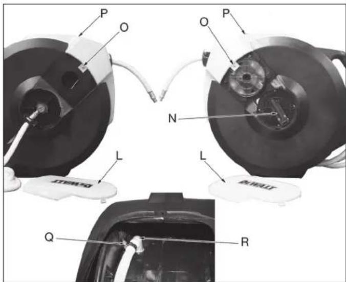
- Remove the covers (L) from both sides of the hose reel.
- Disconnect the air supply from the hose reel.
- Remove the 2 screws (O) that holds the front cover (P) in place.
-
Remove the front cover.
-
Remove the ball stop by pulling up on the ratchet lock. Set aside.
- Carefully pull all of the air hose from the hose reel and then lock in this position. Do not allow the hose to retract back.
WARNING: The reel is under tension so do not turn the hose reel drum or pull on the hose while it is locked. - Using the crank (N) on the right side of the hose reel, rotate counterclockwise until the spring is feeling loose and the hose does not retract back.
- Spin the wheel manually to the position where the hose can easily be removed.
- Loosen the hose clamp (Q) and remove the old hose.
- Push the new hose onto the elbow (R) and tighten the hose clamp.
- Using the crank (N) on the right side of the hose reel, rotate clockwise until the spring has tension. Pull the hose to unlock and slowly rewind the air hose. Do not let go of the hose. Push the crank handle back to lock in place.
- Assemble the front cover back onto the hose reel & tighten the 2 screws.
- Re-attach the ball stop to the desired location on the hose.
- Place the side covers back onto the hose reel.
- Reconnect the air supply. Check all connections to make sure there are no leaks.
SERVICE INFORMATION
Please have the following information available for all service calls: Model Number
Date and Place of Purchase
FREE WARNING LABEL REPLACEMENT: If your warning labels become illegible or are missing, call 1-800-4-DEWALT for a free replacement.
WARRANTY
ONE YEAR LIMITED WARRANTY: DeWALT Industrial Tools (the Company) warrants that for a period of twelve (12) months from the date of purchase, it will replace or repair, free of charge, for the original retail purchaser only, any part or parts, manufactured by the Company, found upon examination by the Company or its assigned representatives, to be defective in material or workmanship or both. All transportation charges for parts submitted for replacement or repair under this warranty must be borne by the original retail purchaser. This is the exclusive remedy under this warranty.
Failure by the original retail purchaser to install, maintain and operate said equipment in accordance with good industry practices, or failure to comply with the specific recommendations of the Company set forth in the owner's manual, shall render this warranty null and void. The Company shall not be liable for any repairs, replacements, or adjustments to the equipment or any costs for labor performed by the purchaser without the Company's prior written approval. The effects of corrosion, erosion and normal wear and tear are specifically excluded from this warranty.
THE COMPANY MAKES NO OTHER WARRANTY OR REPRESENTATION OF ANY KIND WHATSOEVER, EXPRESSED OR IMPLIED EXCEPT THAT OF TITLE. ALL IMPLIED WARRANTYES, INCLUDING ANY WARRANTY OF MERCHANTABILITY AND FITNESS FOR PARTICULAR PURPOSE ARE HEREBY DISCLAIMED. LIABILITY FOR CONSEQUENTIAL AND INCIDENTAL DAMAGES UNDER ANY AND ALL WARRANTYES, OTHER CONTRACTS, NEGLIGENCE, OR OTHER SORTS IS EXCLUDING TO THE EXTENT EXCLUSION IS PERMITTED BY LAW.
Notwithstanding the above, any legal claim against the Company shall be barred if legal action thereon is not commenced within twenty-four (24) months from the date of purchase or delivery whichever occurs last. This warranty constitutes the entire agreement between the Company and the original retail purchaser and no representative or agent is authorized to alter the terms of same without expressed written consent of the Company.
CAUTION: Risk OF IMPAIRY OR not get off those with the disease.
ATTENTION: RISQUE OF BLESSURES. No one can replace his laux d'etre en remb赎age.
BLOODING: The blood of LEJNESHOLES. No one can replace his mezzanine du cremeur.

GARANTIE
DEWALT Industrial Tool Co., 701 Joppa Road, Baltimore, MD 21286
(FEB18) Part No.DXCM024-0345 Copyright © 2017, 2018 DEWALT
The following are trademarks for one or more DeWALT power tools: the yellow and black color scheme; the "D" shaped air intake grill; the array of pyramids on the handgrip; the kit box configuration; and the array of lozenge-shaped humps on the surface of the tool.
