D55155 - Compressor DEWALT - Free user manual and instructions
Find the device manual for free D55155 DEWALT in PDF.

User questions about D55155 DEWALT
0 question about this device. Answer the ones you know or ask your own.
Ask a new question about this device
Download the instructions for your Compressor in PDF format for free! Find your manual D55155 - DEWALT and take your electronic device back in hand. On this page are published all the documents necessary for the use of your device. D55155 by DEWALT.
USER MANUAL D55155 DEWALT
DeWALT Industrial Tool Co., 701 East Joppa Road, Baltimore, MD 21286 (JUL03) Form No. 5135175 Copyright © 2003 DeWALT The following are trademarks for one or more DeWALT power tools: the yellow and black color scheme; the "D" shaped air intake grill; the array of pyramids on the handgrip; the kit box configuration; and the array of lozenge-shaped humps on the surface of the tool.
Questions? See us on the World Wide Web at www.dewalt.com
INSTRUCTION MANUAL
GUIDE D'UTILISATION
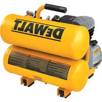
D55150, D55151, D55152, D55153, D55155
Contractor's Electric 4 Gallon Hand Carry Air Compressor
text_image
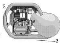
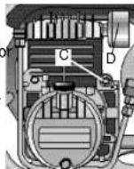
A B C D E F EVALVESAFETY RELIEF VALVE
text_image
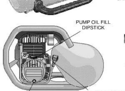
PUMP OIL FILL DIPSTICKPUMP OIL DRAIN
ON / OFF LEVER
MOTOR RESET
SWITCH

TANK DRAIN
- VALVE
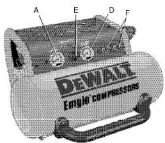
A. TANK PRESSURE GAUGE
B. ON/OFF LEVER
C. PRESSURE SWITCH
D. REGULATED PRESSURE GAUGE
E. REGULATOR
F. COUPLER
G. PUMP OIL FILL DIPSTICK
H. PUMP OIL DRAIN
I. MOTOR RESET SWITCH
J. DRAIN VALVE
K. SAFETY RELIEF VALVE

text_image
G H I
natural_image
Five identical DeniMax air purifiers with different designs and colors, displayed side by side (no text or labels visible on the devices themselves)SPECIFICATIONS
| MODEL D55150 D55151 D55152 D55153 D55155 | |||||
| WEIGHT 57 lbs. 53 lbs. 65 lbs. 56 lbs. 61 lbs. | |||||
| HEIGHT 16.75 in. 16.75 in. 16.0 in. 16.75 in. 12.5 in. | |||||
| WIDTH | 18.0 in. | 18.0 in. | 18.0 in. | 18.0 in. | 21.75 in. |
| LENGTH | 15.0 in. | 15.0 in. | 18.0 in. | 15.0 in. | 21.75 in. |
| MOTOR | 1 HP,120 V. | 2 HP, 120 V. | 2.75 HP, 120 V. | 2.75 HP, 120 V. | 2.75 HP, 120 V. |
| 12 A. 60 Hz. | 14 A. 60 Hz. | 14 A. 60 Hz. | 15 A. 60 Hz. | 15 A. 60 Hz. | |
| 1725 RPM | 3450 RPM | 3450 RPM | 3450 RPM | 3450 RPM | |
| PUMP OIL | 4 oz. | 6 oz. | 12 oz. | 4 oz. | 4 oz. |
| CFM/PSI | 4.0@40 | 4.8@40 | 5.1@40 | 5.4@40 | 5.4@40 |
| 3.4@60 4.4@60 4.6@60 | 5.1@60 5.1@60 | ||||
| 2.8@90 3.8@90 4.0@90 | 4.6@90 4.6@90 | ||||
| 2.6@100 | 3.6@100 | 3.8@100 4.5@100 4.5@100 | |||
IF YOU HAVE ANYQUESTIONS OR COMMENTS ABOUT THIS OR ANY DEWALT TOOL, CALL US TOLL FREE AT 1-800-4-DEWALT (1-800-433-9258).
⚠ WARNING! Read and understand all instructions before operating this compressor. Failure to follow all instructions listed below may result in electric shock, fire and/or serious personal injury
SAVE THESE INSTRUCTIONS
Safety Instructions
⚠ WARNING: Some dust created by this product contains chemicals known to State of California to cause cancer, birth defects or other reproductive harm. Some examples of these chemicals are:
• compounds in fertilizers
• compounds in insecticides, herbicides and pesticides
• arsenic and chromium from chemically treated lumber
To reduce your exposure to these chemicals, wear approved safety equipment such as dust masks that are specially designed to filter out microscopic particles.
⚠ WARNING: Use of this product will expose you to chemicals known to the State of California to cause cancer, birth defects and other reproductive harm. Avoid inhaling vapors and dust, and wash hands after using.
⚠ WARNING: This product contains chemicals, including lead, known to the State of California to cause cancer, and birth defects or other reproductive harm. Wash hands after handling.
The user of the air compressor must understand these instructions. Each person operating the air compressor must be of sound mind and body and must not be under the influence of any substance which might impair vision, dexterity, or judgement.
AIR TANK
The tank on your Air Compressor is designed and may be UM coded (for units with tanks greater than 6 inch diameter)
according to ASME Section VIII, Div. 1 rules. All pressure vessels must be inspected once every two years. To find your state pressure vessel inspector, I look under the Division of Labor and Industries in the government section of a phone book or call 1-800-4DEWALT for assistance.
The following conditions could lead to a weakening of the tank, and result in a violent tank explosion:
- Failure to properly drain condensed water from the tank, causing rust and thinning of the steel tank. Drain tank daily or after each use. If tank develops a leak, replace it immediately with a new tank or new compressor outfit.
- Modifications or attempted repairs to the compressor tank. Never drill into, weld, or make any modifications to the tank or its attachments.
- Modifications of the pressure switch, safety valve, or any other components that control tank pressure. The tank is designed to withstand specific operating pressures. Never make adjustments or substitute parts to alter the factory set operating pressures.
ATTACHMENTS & ACCESSORIES
Exceeding the pressure rating of air tools, spray guns, air operated accessories, tires and other inflatables can cause them to explode or fly apart, resulting in serious injury. Follow the
equipment manufacturers recommendation and never exceed the maximum allowable pressure rating of attachments. Never use the compressor to inflate small, low-pressure objects such as children's toys, footballs, basketballs, etc..

RISK OF EXPLOSION OR FIRE
It is normal for electrical contacts within the motor and pressure switch to spark. Always operate the compressor in a well-ventilated area free of combustible materials, gasoline or solvent vapors, electrical sparks from compressor come into contact with flammable vapors, they may ignite, causing fire or explosion. When spraying flammable materials, pressor at least 20 feet upwind from spray area. A few of hose may be required.

Store flammable materials in a secure location away from the compressor.
Restricting any of the compressor ventilation openings will cause serious overheating and could cause fire. Never place objects against or on top of compressor. Operate the compressor in an open area at least 3 feet away from any wall or obstruction that would restrict the flow of fresh air to the ventilation openings.
RISK OF ELECTRICAL SHOCK
Your air compressor is powered by electricity. If it is not used properly it could cause electric shock. Never operate the compressor outdoors when it is raining or in wet conditions.

Never operate compressor with guards or protective covers that are damaged or removed. Repairs by anyone other than qualified personnel can result in serous injury or death by electrocution. Any electrical wiring or repairs required on this product should be performed by authorized service center personnel in accordance with national and local electrical codes.
GROUNDING INSTRUCTIONS
In the event of a malfunction or breakdown, grounding provides a path of least resistance for electric current to reduce the risk of electric shock. This tool is equipped with an electric cord having an _2
equipment-grounding conductor and grounding plug. The plug must be plugged into a matching outlet that is properly installed and grounded in accordance with all local codes and ordinances. Do not modify plug provided: if it will not fit the outlet, have the proper outlet installed by a qualified electrician.
Improper connection of the equipment-grounding conductor can result in a risk of electric shock. The conductor with insulation having an outer surface that is green with or without yellow stripes is the equipment-grounding conductor. If repair or replacement of the electric cord or plug is necessary do not connect the equipment-grounding conductor to a live terminal.
If the grounding Instructions are not completely understood or if in doubt as to whether the tool is properly grounded, check with a qualified electrician or service personnel.
Use only 3-wire extension cords that have 3-prong grounding plugs and 3-pole receptacles to avoid overheating.
REPAIR OR REPLACE DAMAGED OR WORN CORDS IMMEDIATELY.
THE USE OF A GFCI OUTLET IS RECOMMENDED AND MAY BE REQUIRED IN CERTAIN AREAS.
Grounded tools intended for use on a supply circuit having a nominal rating less than 150 volts: This tool is intended for use on a circuit that has an outlet that looks like the one illustrated in Figure A. The tool has a grounding plug that looks like the plug illustrated in Figure A. A temporary adapter, which looks like the adapter illustrated in Figures B and C, may be used to connect this plug to a 2-pole receptacle as shown in Figure B if a properly grounded outlet is not available. The temporary adapter should be used only until a

text_image
A GROUNDED OUTLET BOX B GROUNDING PIN C GROUNDING MEANS ADAPTERproperly grounded outlet can be installed by a qualified electrician, The green-colored rigid ear, lug, and the like, extending from the adapter must be connected to a permanent ground such as a properly grounded outlet box.
The adapter (C) is not for use in Canada.
DEWALT does not recommend the use of extension cords. This can create power loss and overheating of the motor. Use an additional air hose rather than an extension cord. If use of an extension cord is unavoidable, it should be plugged into a GFCI found in circuit boxes or protected receptacles. When using an extension cord, observe the following.
| Extension Cord Chart | ||
| 1 Hp Motor Rating Length of Cord in Feet25' 50' 100' | ||
| 12 amp, 115V 14 Ga. | 12 Ga. | 10 Ga. |
| 2 Hp Motor Rating Length of Cord in Feet25' 50' 100' | ||
| 15 amp, 115V 14 Ga. | 12 Ga. | 8 Ga. |
RISK FROM FLYING OBJECTS
The compressed air stream can cause soft tissue damage to exposed skin and can propel dirt, chips, loose particles and small objects at high speed, resulting in serious injury. Always wear ANSI
Z28.1 approved safety glasses with side shields when using the compressor. Never direct air stream at people or animals. Use only OSHAapproved air blow guns.
RISK TO BREATHING
The compressed air from your compressor is not safe for breathing! The air stream may contain carbon monoxide, toxic vapors or solid particles. Never inhale air from the compressor either directly or from a breathing device connected to the compressor.

Sprayed materials such as paint, paint solvents, paint remover, insecticides, weed killers, etc. contain harmful vapors and poisons. NOTE: Operate air compressor only in a well ventilated area. Read and follow the safety instructions provided on the label or safety data sheets for the material you are spraying. Use a NIOSH/MSHA approved respirator designed for use with specific application.
RISK FROM MOVING PARTS
The compressor cycles automatically when the pressure switch is in the ON/AUTO position. Always turn off the compressor, bleed pressure from the air hose and tank, and disconnect from power source before performing maintenance or attaching tools and accessories.

Keep your hair, clothing, and gloves away from moving parts. Loose clothes, jewelry, or long hair can be caught in moving parts. Air vents may cover moving parts and should be avoided as well. Do not remove the protective covers from this product. Never operate compressor with guards or protective covers that are damaged or removed. Never stand on the compressor.
RISK OF BURNS
Touching exposed metal such as the compressor head or aftercooler can result in serious burns. Never touch any exposed metal parts
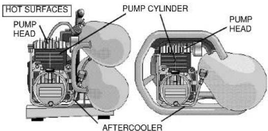
text_image
HOT SURFACES PUMP HEAD PUMP CYLINDER PUMP HEAD AFTERCOOLERon compressor during or immediately after operation. Compressor will remain hot for several minutes after operation. Do not move the compressor while it is running. Hot motor parts could cause burns contribute to the dropping of the compressor, damaging the compressor and/or injuring the operator.

RISK FROM NOISE
⚠ CAUTION: Wear appropriate personal hearing protection during use. Under some conditions and duration of use, noise from this product may contribute to hearing loss.

Introduction
Congratulations on the purchase of your new DEWALT Air Compressor! You can be assured that this tool has been constructed with the highest level of precision and accuracy. Each component has been rigorously tested by technicians to ensure the quality, endurance and performance of this air compressor.
By reading the following simple safety, installation, operation,
maintenance and troubleshooting steps described in this manual, you will receive years of trouble-free operation. The manufacturer reserves the right to make changes in price, color, materials, equipment specifications, or models at any time without notice.
Inspection of Compressor
Inspect for signs of obvious or concealed freight damage. Report any damage to the delivering freight carrier immediately. Be sure that all damaged parts are replaced and any mechanical problems are corrected prior to the operation of the air compressor. The air compressor serial number is located on the shroud of the compressor. Please write the serial number in the space provided in the service section for future reference.
⚠ WARNING: When using electric tools, basic safety precautions should always be followed to reduce risk of fire, electric shock, and personal injury.
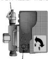
DEWALT Air Compressor Features PRESSURE SWITCH
This switch (A) is used to start or stop the air compressor. Moving the switch to the ON position will provide automatic power to the pressure switch which will allow the motor to start when the air tank pressure is below the factory set cut-in pressure. When in the ON (AUTO) position, the pressure switch stops the compressor from
charging air when the air tank pressure reaches the factory set cut-out pressure limit. For ease of starting, this switch also has a pressure release valve located on the side of the switch designed to automatically release compressed air from
the air compressor pump head and its dischar line when the air compressor reaches the cut-out pressure limit or is shut off. Moving the switch to the OFFposition will open the
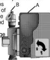
pressure switch contacts and stop the air compressor.
SAFETY RELIEF VALVE
This valve (B) is designed to prevent system failures by relieving pressure from the system when the compressed air reaches a predetermined level. The valve is preset by the manufacturer and must not be modified in any way.
AIR TANK DRAIN VALVE
The drain valve is used to remove moisture from the air tank after the air compressor is shut off.
MOTOR THERMAL OVERLOAD
The electric motor has a manual thermal overload protector (C). If the motor overheats for any reason, the thermal overload will cut off power, thus preventing the motor from being damaged. Turn the pressure switch to the OFF position and wait until the motor cools before pressing the thermal overload button.
AIR INTAKE FILTER
This filter (D) is designed to clean air entering the pump. To ensure the pump continually receives a clean, cool, and dry air supply this filter must always be clean and the filter intake must be free from obstructions.
TANK PRESSURE GAGE
The tank pressure gage indicates air pressure in the air tank.
REGULATED PRESSURE GAGE
The regulated pressure gage indicates the air pressure available at the outlet side of the regulator. This pressure is controlled by the regulator and is always less than or equal to the air tank pressure.
PRESSURE REGULATOR
The regulator knob controls the air pressure coming from the air tank.
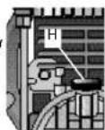
OIL DIPSTICK
The dipstick (H) will indicate the amount of oil in the pump. Oil level should be checked on a daily basis to ensure that it does not exceed the maximum notch or fall below the minimum notch on the dipstick.
Common Procedures
CHECKING COMPRESSOR PUMP OIL LEVEL
⚠ WARNING: Aftercooler, pump head, and surrounding parts are very hot. Do not touch. (see Hot Surfaces on page 4).
-
Ensure that the unit is off.
-
Locate unit on a flat horizontal surface.
-
Remove dipstick (H) from oil fill port.
-
Look for visual signs of contaminants (water, dirt, etc.) in oil on dipstick.
5.Wipe oil off of the dipstick.
-
Reinsert the dipstick fully into the oil fill port for a few seconds to allow oil to collect on dipstick.
-
Remove the oil dipstick to read oil level. Oil should not exceed top raised line (MAX) on dipstick. If oil is below lower mark (MIN), add DEWALT synthetic oil MAX and follow steps 5 through 7.
CHECKING SAFETY RELIEF VALVE OPERATION
⚠ WARNING: Aftercooler, pump head, and surrounding parts are very hot. Do not touch (see Hot Surfaces on page 4).
- Ensure that the unit is off.
- Ensure that the tank is empty by looking at tank pressure gage. Drain the tanks if necessary.
- Grasp the wire ring on the safety valve.
- Pull and release the ring a few times to ensure that the plunger moves in and out. Replace the safety valve if plunger does not
move or is difficult to move.
CHECKING AIR FILTER ELEMENT
WARNING: Aftercooler, pump head, and surrounding parts are very hot. Do not touch (see Hot Surfaces on page 4).
-
Ensure that the unit is off.
-
Allow the unit to cool.
-
Unscrew the filter from pump head by turning counter clockwise.
-
Separate the filter body into two halves.
-
If the element needs cleaning blow out with air. Replace air filter assembly if unsure whether element can be cleaned sufficiently.
-
Reconnect the filter body.
-
Screw the filter into pump head by turning clockwise until the filter is hand tight.
TURNING THE UNIT ON
Follow the pre-start and start-up procedures in the operating procedure section.
Follow the shut-down procedures in the operating procedures section.
ADJUSTING THE REGULATOR
-
Pull the regulator knob out. (For D55155 compressor)
-
Turn the knob clockwise to increase regulated pressure and counter clockwise to decrease regulated pressure.
-
When desired pressure is shown on the regulated pressure gage, push the knob in to lock it. (For D55155 compressor)
INSTALLING HOSES
⚠ WARNING: Firmly grasp the hose when installing or disconnecting to prevent hose whip.
-
Ensure that the regulated pressure gage reads 0 PSI.
-
Grasp the hose at the coupler.
-
Pull back the collar on the female quick-connect coupler located on the compressor.
-
Push the male connector into the female connector.
-
Release the female connector.
-
Grasp hose and pull to ensure couplers are seated.
-
Adjust regulator to desired pressure.
DISCONNECTING HOSES
⚠ WARNING: Firmly grasp the hose when installing or disconnecting to prevent hose whip.
-
Ensure that the regulated pressure gage reads 0 PSI.
-
Grasp the hose at the coupler.
-
Pull back the collar on female quick-connect coupler located on the compressor.
-
Pull the male connector out of the female connector.
-
Release the female connector.
DRAINING THE TANK
⚠ WARNING: The tank contains high pressure air. Keep the outlet of drain away from face and other body parts. Use safety glasses when draining because debris can be kicked up into face. Use ear protection because air flow noise is loud when draining.
NOTE: All compressed air systems generate condensate that accumulates in any drain point (e.g. tanks, filter, aftercoolers, dryers). This condensate contains lubricating oil and/or substances which may be regulated and must be disposed of in accordance with local, state, and federal laws and regulations.
-
Ensure that the ON/OFF switch is in the OFF position.
-
Move the compressor into an inclined position so that the drain valve(s) are at the lowest point This will assist in removing moisture, dirt, etc. from the tanks.
-
Place a suitable container under the drain to catch discharge.
-
Open the valve from below, keeping hands away from hot components.
5.Slowly rotate the lever or turn knob counter clockwise to gradually bleed air from tank.
-
When tank is at 10 PSI, rotate the lever or knob to the fully open position.
-
Close the drain valve when finished.

Preparation For Use INITIAL SET-UP
Read all safety instructions before setting-up air compressor.
-
Remove oil plug.
-
Pour DEWALT synthetic oil into crankcase (See Specifications).
⚠ WARNING: THE COMPRESSOR IS SHIPPED WITHOUT OIL IN THE CRANKCASE. ADD OIL.
-
Insert dipstick.
-
Close air tank drain valve.
CAUTION: Do not operate without lubricant or with inadequate lubricant. DeWALT is not responsible for compressor failure caused by inadequate lubrication.
Compatibility
Air tools and accessories that are operated with the compressor must be compatible with petroleum based products. If you suspect that a material is not compatible with petroleum products, use an air line filter for removal of moisture and oil vapor in compressed air. NOTE: Always use an air line filter to remove moisture and oil vapor when spraying paint.
Location
⚠CAUTION: In order to avoid damaging the air compressor, do not allow the unit to be tilted more than 10^ from the normal horizontal
position when operating.
All hand carry compressors should be run with the rubber feet resting on a horizontal, flat surface.
Place the air compressor at least 3 feet away from obstacles that may prevent proper ventilation. Keep the compressor away from areas that have dirt and/or volatile fumes in the atmosphere. These impurities may clog the intake filter and valves, causing inefficient operation.
NOTE: The D55155 single tank air compressor is designed to be carried in the vertical orientation but will right itself in the proper horizontal position when placed on a flat surface.
HUMID AREAS
In frequently humid areas, moisture may form in the bare pump and produce sludge in the lubricant, causing running parts to wear out prematurely. Excessive moisture is especially likely to occur if the unit is located in an unheated area that is subject to large temperature changes. Two signs of excessive humidity are external condensation on the bare pump when it cools down and a "milky" appearance in compressor lubricant. You may be able to prevent moisture from forming in the bare pump by increasing ventilation or operating for longer intervals.
ELECTRICAL
Refer to the safety instructions before using unit. Observe extension cord safety instructions if necessary. Always shut off the air compressor switch before removing the plug from the outlet.
NOISE CONSIDERATIONS
Consult local officials for information regarding acceptable noise levels in your area. To reduce excessive noise, use vibration mounts or silencers, relocate the unit or construct total enclosures or baffle walls. Contact a DEWALT service center or call 1-800-4DEWALT for
assistance.
TRANSPORTING
When transporting the compressor in a vehicle, trailer, etc., ensure that the tanks are drained and the unit is secured. Use care when driving to avoid tipping the unit over in the vehicle. Damage can occur to the compressor or surrounding items if the compressor is tipped.
MOVING
When moving the compressor, grasp the handle grip and carry the compressor as close to your body as possible.
⚠ WARNING: Ensure proper footing and use caution when carrying compressor to avoid a loss of balance.
Air Inlet Filter
⚠️CAUTION: Do not operate without the air inlet filter.
General Requirements
The piping, fittings, receiver tank, etc. must be certified safe for at least the maximum working pressure of the unit. Use hard welded or threaded steel or copper pipes, cast iron fittings and hoses that are certified safe for the unit's discharge pressure and temperature. Use pipe thread sealant on all threads and tighten joints thoroughly to prevent air leaks. DO NOT USE PVC PLASTIC.
CONDENSATE DISCHARGE PIPING
To install a condensate discharge line, use piping at least one size larger than the connection. Connect the piping so that it is secured tightly and is routed to a suitable drain point. Use as short and direc a pipe as possible. Condensate must be disposed of in accordance with local, state, and federal laws and regulations.
NOTE: All compressed air systems generate condensate that accumulates in any drain point (e.g. tanks, filter, aftercoolers and dryers). This condensate contains lubricating oil and/or substances
which may be regulated and must be disposed of in accordance with local, state, and federal laws and regulations.
Operating Procedures
PRE-START CHECKLIST
-
Ensure that the ON/OFF lever switch is in the OFF position.
-
Ensure that the tank is drained so that moisture, dirt, etc. can be eliminated.
3.Ensure that the tank pressure gage reads 0 PSI.
-
Ensure that the safety and drain valves are functioning properly.
-
Ensure that the drain valve is closed.
-
Check the oil level in the pump.
NOTE: The air compressor is shipped without oil in crankcase. Add oil before using.
- Ensure that all guards and covers are in place and securely mounted. Ensure that all labels are legible. Do not use the compressor until all these items have been verified.
START-UP
-
Ensure that the ON/OFF lever on the pressure switch is in the OFF position.
-
Pull out and turn the regulator knob counterclockwise until it is fully closed. Push in to lock. The regulated pressure gage should read 0 PSI.
3.Plug the power cord into a grounded outlet.
- Move the ON/OFF lever to the ON position. Allow the compressor to reach cut-out pressure limit. This pressure will cause the compressor to shut down automatically.
NOTE: When the compressor is started and the tank is empty, an air noise will be heard. This noise is normal as the cold start valves are allowing air to escape from the air compressor lines. This noise
will also be heard when the unit shuts off because the unloader valve, located in the pressure switch, is purging air from the lines.
-
Attach the hose and accessory.
-
Adjust the regulator to the desired setting.
NOTE: If any unusual noise or vibration is noticed, stop the compressor and refer to the troubleshooting section.
Shut-down
NOTE: NEVER stop the air compressor by unplugging it from the power source. This could result in damage to the unit.
- Move the ON/OFF lever to the OFF position.
NOTE: If finished using compressor, follow steps 2 - 7 below. - Unplug the cord from the outlet.
- Turn the regulator knob counterclockwise until it is fully closed. Ensure that the regulated pressure gage reads 0 PSI.
- Remove the hose and accessory.
- Drain the air tanks.
- Allow the compressor to cool down.
- Wipe compressor clean and store in a safe, non-freezing area.
Maintenance
The following procedures must be followed when maintenance or service is performed on the air compressor.
- Turn off the compressor.
- Disconnect cord from electrical outlet.
3.Drain tanks. - Allow the compressor to cool down before starting service.
NOTE: All compressed air systems contain maintenance parts (e.g. lubricating oil, filters, separators) which are periodically replaced. These used parts may be, or may contain, substances that are regulated and must be disposed of in accordance with local, state,
and federal laws and regulations.
NOTE: Take note of the positions and locations of parts during disassembly to make reassembly easier. The assembly sequences and parts illustrated may differ for your particular unit.
NOTE: Any service operations not included in this section should be performed by authorized service personnel.
Maintenance Chart
ProcedureDayWeekMonth200 Hrs.
Check pump oil level X
Oil leak inspection X
Drain condensation in air tank(s) X
Check for unusual noise/vibration X
Check for air leaks ^** X
Inspect air filter X
Clean exterior of compressor X
Check safety relief valve X
Change pump oil * Replace air filter X X
* The pump oil must be changed after the first 20 hours of operation. Thereafter, every 200 hours or once a year, whichever comes first. In harsh environments, maintenance must be performed on an accelerated schedule. Always use DEWALT synthetic oil.
** To check for air leaks apply a solution of soapy water around joints While the compressor is reaching the pressure cut-out limit and after the pump cuts out, look for air bubbles around the joints.
Compressor Pump Oil Change
NOTE: Pump oil contains substances that are regulated and must be disposed of in accordance with local, state, and federal laws and
regulations.
WARNING: Aftercooler, pump head, and surrounding parts are very hot. Do not touch (see Hot Surfaces on page 4).
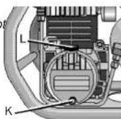
1. Ensure that the unit is off.
2. Allow the unit to cool.
3. Place a suitable container under the drain plug (K).
4. Remove the oil dipstick (L) from crank-case.
5. Remove the oil drain plug.
6. Allow ample time for all the oil to drain out. (Tilting the compressor towards the drain plug assists draining.)
7. Reinstall the oil drain plug.
8. Fill the pump with DEWALT synthetic compressor oil (See Specifications).
9. Reinstall the oil dipstick.
Accessories
Recommended accessories for use with your tool are available for purchase from your local dealer or authorized service center. If you need assistance in locating any accessory for your tool, contact: DeWALT Industrial Tool Co., 701 East Joppa Road, Baltimore, MD 21286 or call 1-800-4-DEWALT.
CAUTION: The use of any other accessory not recommended for use with this tool could be hazardous.
SERVICE
Please have the following information available for all service calls:
Model Number
Serial Number
Date and Place of Purchase
Repairs
To assure product SAFETY and RELIABILITY, repairs, maintenance and adjustment should be performed by authorized service centers or other qualified service organizations, always using identical replacement parts.
Full One Year Warranty
DEWALT heavy duty industrial tools are warranted for one year from date of purchase. We will repair, without charge, any defects due to faulty materials or workmanship. For warranty repair information, call 1-800-4-DEWALT. This warranty does not apply to accessories or damage caused where repairs have been made or attempted by others. This warranty gives you specific legal rights and you may have other rights which vary in certain states or provinces.
FREE WARNING LABEL REPLACEMENT: If your warning labels become illegible or are missing, call 1-800-4-DEWALT for a free replacement.
TROUBLESHOOTING GUIDE
This section provides a list of the more frequently encountered malfunctions, their causes and corrective actions. The operator or maintenance personnel can perform some corrective actions, and others may require the assistance of a qualified DeWALT technician or your dealer.
ProblemCode
Compressor does not start or restart 16,17,18,19,20,36
Unit does not or is slow to come up to speed 3,8,11,12,14,15,20,21,22,24,25,31
Air compressor not making enough air....1,3,7,8,9,10,11,21,24,25,28,29
Insufficient pressure at air tool or accessory 1,3,7,8,9,10,11,21,24,25,27,28,29
High oil consumption....2,1 1,12,15,30,32
Unit runs excessively hot 1,2,4,5,10,1113,15,19,30
Excessive starting and stopping 7,20,21,24,25,29
Excessive noise during operation 2,3,4,5,8,9,10,110,31
Moisture in discharge air 34,35
Moisture in crankcase or "milky" appearance in petroleum lubricant or rusting in cylinders .....6,7,9,10,15,25,26,33,35
Oil in discharge air (oil pumping) 2,6,8,9,10,11,15,31,32
Oil leaking from shaft seal....12
Safety relief valve "pops" 22,23
Air leaks at pump 25
Air leaks at fittings 25
Air leaks from tank 26
Abnormal piston ring or cylinder wear 2,4,5,6,9,10,11,13
Code Possible Cause Possible Solution
- Clogged or dirty inlet and/or discharge line filter. Clean or replace air inlet and/or discharge line filter.
- Lubricant viscosity too low. Drain existing lubricant and refill with DEWALT Synthetic lubricant.
3 Lubricant viscosity too high. Drain existing lubricant and refill with DEWALT Synthetic lubricant. - Lubricant level too low. Add lubricant to crankcase to proper level
- Detergent type lubricant being used. Drain existing lubricant and refill with DEWALT Synthetic lubricant.
- Extremely light duty cycles. Run unit for longer duty cycles.
- Air leaks in air discharge piping. Check tubing and connections.
-
Compressor pump check valve is loose, broken, Inspect valve. Clean or replace as required.
or has carbon buildup -
Carbon build up on top of compressor pump piston. Clean piston. Repair or replace as required.
10 Piston rings damaged or worn Install new rings.
(broken, rough, or scratched). Excessive end gap or
side clearance. Piston rings not seated, stuck
in grooves, or end gaps not staggered.
11 Cylinder or piston scratched, worn, or scored. Repair or replace as required
12 Worn connecting rod, piston pin, or crankpin bearings. Inspect all. Repair or replace as required..
13 Crankshaft seal worn or crankshaft scored. Replace seal or crankshaft assembly.
14 Extremely dusty atmosphere. Install more effective filtration or relocate the compressor.
15 Ambient temperature too low. Relocate compressor to warmer environment. Ensure that DEWALT Synthetic oil is in crankcase.
16 Worn cylinder finish. Deglaze cylinder with 180 grit flex-hone
17 Power cord not plugged in. Plug cord into grounded outlet
18 Pressure switch is in OFF position. Move switch to ON/AUTO position.
19 Motor thermal overload switch has tripped. Turn the compressor off, wait until motor is cool, then press motor thermal overload button (located on motor) firmly until a click is heard. Replace fuse or reset circuit breaker. Check for proper fuse. Use only "Fusetron" type T fuses. Check for low voltage conditions. Disconnect any other electrical appliances from circuit or operate the compressor on its own branch circuit.
21 Wrong gage wire or length of extension cord. If possible, eliminate extension cord. Check the chart on page 7 for proper gage wire and cord length.
| Code Possible Cause Possible Solution | ||
| 22 | Tank air pressure exceeds pressure switch Set pressure switch in the "Auto" position. The motor will "cut-in" setting, automatically start when air tank pressure drops below "cut-in" pressure. | |
| 23 | Pressure relief valve on pressure switch has Drain tanks. If problem persists, not unloaded pump head pressure. | contact DEWALT customer service at 1-800-4-DEWALT. |
| 24 | Defective motor, motor capacitor, or pressure switch. | Contact DEWALT Customer Service at 1-800-4-DEWALT. |
| 25 | Pressure switch does not shut off motor when Move the pressure switch to the OFF position. | |
| air compressor reaches "cut-out" pressure. If the motor does not shut off, unplug the air compressor. If the electrical contacts are welded together, replace the pressure switch. | ||
| 26 | Air compressor is not large enough for air required. | Check accessory air requirement. If higher than the CFM or pressure supply of the air compressor, then larger air compressor is required. |
| 27 | Defective pressure switch. Replace the pressure switch. | |
| 28 | Defective safety relief valve. | Operate safety relief valve manually by pulling on test ring. If it still leaks, replace the safety relief valve. |
| 29 | Excessive air tank pressure. | Defective pressure switch. Replace the pressure switch. |
| 30 | Defective gaskets. | Replace and torque head bolts to 6 to 7 ft lbs. |
| 31 | Fittings not tight enough. | Warning: Drain air before tightening. Tighten fittings so air can not be heard escaping. Check joint with soap solution. Do not overtighten |
| 32 | Defective or rusted air tank | Air tank must be replaced. Do not attempt to repair air tank. |
| 33 | Pressure regulator knob not turned to high enough pressure or defective pressure regulator. | Adjust pressure regulator knob to proper setting or replace. |
| 34 | Hose or hose connections are too small or too long. | Replace with larger hose or connectors. |
| 35 | Possible defective reed valve. | Remove pump head and inspect valve plate and reed valve. Clear or replace valves as required. |
| 36 | Air compressor on uneven surface. | Do not incline the air compressor more than 10^ in any direction while running. |
| 37 | Crankcase overfilled with oil. | Drain oil. Refill to proper level with DEWALT synthetic oil. |
| 38 | Plugged oil dipstick vent. | Clean dipstick vent. |
| 39 | Water in oil due to condensation. | Drain oil. Refill to proper level with DEWALT synthetic oil. |
| 40 | Condensation in air tank caused by high level of atmospheric humidity. | Drain air tank after every use. Drain air tank more often in humid weather and use an air line filter. |
| 41 | Compressor located in damp or humid location. | Relocate the compressor. |

natural_image
Five identical industrial gas turbine units with different internal designs and branding, shown from different angles (no visible text or labels)| SPECIFICATIONS | |||||
| MODELE D55150 D55151 D55152 D55153 D55155 | |||||
| POIDS 25,85 kg 24,0 kg 24,94 kg 25,4 kg 27,67 kg | |||||
| HAUTEUR | 42,5 cm | 42,5 cm | 62,4 cm | 42,5 cm | 48.75 cm |
| LARGEUR | 70,2 cm 70,2 cm 70,2 cm 70,2 cm 84,82 cm | ||||
| LONGEUR | 58,5 cm 58,5 cm 70,2 cm 58,5 cm 84,82 cm | ||||
| MOTEUR | 1 HP,120 V.12 A. 60 Hz.1725 RPM | 2 HP, 120 V.14 A. 60 Hz.3450 RPM | 2.75 HP, 120 V.14 A. 60 Hz.3450 RPM | 2.75 HP, 120 V.15 A. 60 Hz.3450 RPM | 2.75 HP, 120 V.15 A. 60 Hz.3450 RPM |
| HUILDE DE LA POMPE | 118,3 ml. | 177,4 ml. | 236,6 ml. | 118,3 ml. | 118,3 ml. |
| p3/min/PO3 | 4.0@40 4.8@40 5.1@403.4@60 4.4@60 4.6@602.8@90 3.8@90 4.0@902.6@100 | 3.6@100 | 5.4@40 5.4@405.1@60 5.1@604.6@90 4.6@903.8@100 4.5@100 4.5@100 | ||

text_image
PRESSOSTAT RÉGULATEUR MANOMÈTRE RÉGULÉ SOUPAPE DE SÛRETÉ MANOMÈTRE DU RÉSERVOIR LEVIER "ON/OFF" RACCORD RAPIDE JAUGE DE REMPLISSAGE DE L'HUILE DE LA POMPE ORIFICE DE PURGE DE L'HUILE DE LA POMPE INTERRUPTEUR DE RÉENCLENCHEMENT DU MOTEUR SOUPAPE DE SÛRETÉ DEWALI Emuio COMPRESSORS FrançaisSI VOUS AVEZ DES QUESTIONS OU VOUS VOULEZ NOUS FAIRE PART DE VOS COMMENTAIRES CONCERNANT CET OUTIL OU TOUT AUTRE OUTIL DEWALT, COMPOSER SANS FRAIS LE : 1 800 433-9258.
vibrations inhabituels X
EntretienJourSem.Mois200 hrs
natural_image
Five different industrial gas turbine models with visible branding and hatching patterns (no text or symbols on the models themselves)| ESPECIFICACIONES | |||||
| MODELO D55150 D55151 D55152 D55153 D55155 | |||||
| PESO 25,85 kg 24,0 kg 24,94 kg 25,4 kg 27,67 kg | |||||
| ALTURA 42,5 cm 42,5 cm 62,4 cm 42,5 cm 48,75 cm | |||||
| ANCHO 70,2 cm 70,2 cm 70,2 cm 70,2 cm 84,82 cm | |||||
| LONGITUD | 58,5 cm 58,5 cm 70,2 cm 58,5 cm 84,82 cm | ||||
| MOTOR | 1 HP.120 V.12 A. 60 Hz.1725 RPM | 2 HP. 120 V.14 A. 60 Hz.3450 RPM | 2.75 HP. 120 V.14 A. 60 Hz.3450 RPM | 2.75 HP. 120 V.15 A. 60 Hz.3450 RPM | 2.75 HP. 120 V.15 A. 60 Hz.3450 RPM |
| ACEITE DELA BOMBA | 118,3 ml. | 177,4 ml. | 236,6 ml. | 118,3 ml. | 118,3 ml. |
| CFM | 4.0@40 4.8@40 5.1@40 5.4@40 5.4@403.4@60 4.4@60 4.6@60 5.1@60 5.1@602.8@90 3.8@90 4.0@90 4.6@902.6@100 | 3.6@100 | 3.8@100 4.5@100 | 4.5@100 | |
text_image
A E D F DEWALT Emilio compressors
text_image
Labeled diagram of an electric motor with components A through Fnatural_image
Cross-sectional diagram of a portable air conditioner unit showing internal components and casing (no text or labels)


text_image
H G LSI TIENE CUALQUIER PREGUNTAO COMENTARIO ACERCADE ESTA O DE CUALQUIER HERRAMIENTA DEWALT, POR FAVOR LLÁMENOS AL 1-800-4-DEWALT (1-800-433-9258).
text_image
Technical diagram of a mechanical device with labeled components H and C