SouthSpa LH-22 - Toilet Brondell - Free user manual and instructions
Find the device manual for free SouthSpa LH-22 Brondell in PDF.


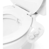
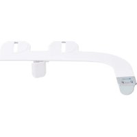
| Product type | Mechanical bidet accessory |
| Brand | Brondell |
| Model | SouthSpa LH-22 |
| Material | Antibacterial ABS, unibody construction |
| Power source | Hydraulic (water pressure), no electrical power required |
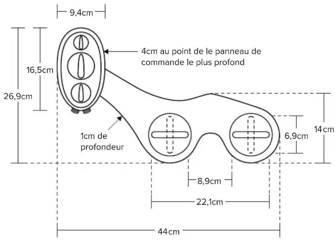
| Dimensions (L × W × H) | 44 cm × 22.1 cm × 9.4 cm |
| Weight | Approximately 1.5 kg |
| Main functions | Front wash (feminine position), rear wash (posterior position), nozzle cleaning |
| Pressure adjustment | Yes, by rotating the control knob |
| Temperature adjustment | Yes, if connected to hot water; otherwise ambient temperature water |
| Nozzles | Retractable, self-cleaning, manually adjustable |
| Maintenance and cleaning | Nozzles cleanable with toothbrush or soft cloth and mild detergent; nozzle cap removable for deep cleaning |
| Safety | Internal ceramic valve with Unibody construction, backflow preventer, pressure plug |
| Warranty | 1-year limited residential (parts and labor) |
| Included parts | Bidet attachment with control knob, adjustable brackets, 7/8" T-fitting for cold water, 63.5 cm braided hose, T-fitting for hot water, hot water flexible tube, hot water plug, rubber washers |
| Installation | Attaches under the toilet seat, connects to cold water supply (and optionally hot water under the sink) |
Frequently Asked Questions - SouthSpa LH-22 Brondell
User questions about SouthSpa LH-22 Brondell
0 question about this device. Answer the ones you know or ask your own.
Ask a new question about this device
Download the instructions for your Toilet in PDF format for free! Find your manual SouthSpa LH-22 - Brondell and take your electronic device back in hand. On this page are published all the documents necessary for the use of your device. SouthSpa LH-22 by Brondell.
USER MANUAL SouthSpa LH-22 Brondell
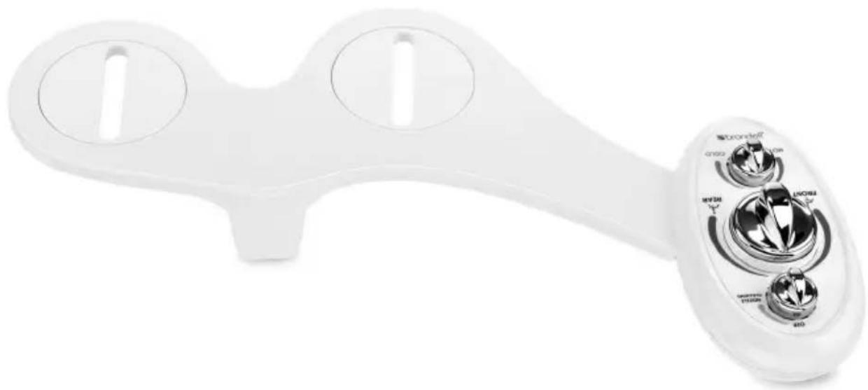
left-handed bidet attachment
OWNER'S MANUAL
LH-22 Bidet Attachment
Dual-Temperature / Dual-Nozzles
natural_image
White medical or laboratory device with two circular ports and a control panel showing dial indicators (no readable text or symbols)Attach Proof of Purchase to This Page
PRODUCT INSTALLATION
Before Installation .... Page 5
Connecting the Cold Water Supply..... Page 6
Connecting the Hot Water Supply..... Page 8
Installing the Bidet Attachment ..... Page 10
PRODUCT OPERATION
Using the SouthSpa.... Page 12
Nozzle Positioning.... Page 12
MAINTENANCE
Cleaning the SouthSpa.... Page 13
Short Term Non-Use ...... Page 13
WARRANTY Page 14
CONTACT Page 15
SPANISH VERSION Page 16
FRENCH VERSION Page 31
PRODUCT INFORMATION
PRODUCT FEATURES
• High-quality ABS material with full body panel
• Hygienic dual retractable nozzles
- Self-cleaning nozzle feature
- Adjustable temperature for ambient and warm water washes
- Positionable nozzles
- Adjustable water pressure
- Ceramic core internal valve with patented uni-body construction for safety
• High-quality metal 7/8" and 3/8" T-valves
• Durable braided metal cold water hose
• High-temperature, durable hot water flex tubing
- No electricity or batteries required
- Easy installation and adjustable toilet fit
- All accessories included for standard installation
• One-year warranty
PARTS LIST
natural_image
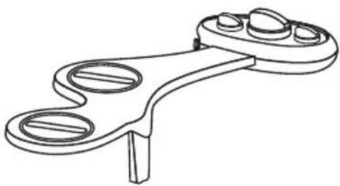
Technical line drawing of a mechanical clamp or lever component (no text or symbols)Bidet attachment with turn-dial control and adjustable brackets
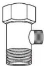
Cold water 7/8" T-valve Connector
natural_image
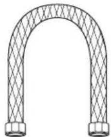
Line drawing of an arched pipe or tube with mesh pattern (no text or symbols)25" braided metal bidet hose
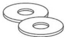
Large rubber washer (2)
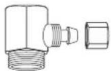
Hot water T-valve with 1/4" Pressure Connector & Pressure Cap (3/8" x 3/8")

natural_image
Simple line drawing of a coiled spring or rope (no text or symbols)1/4" Hot water flex tubing
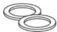
Small rubber washer (2)
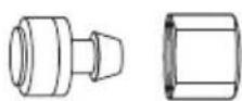
Hot water flex tubing
pressure connector
with pressure cap
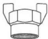
Hot water supply cap
PRODUCT INFORMATION (cont.)
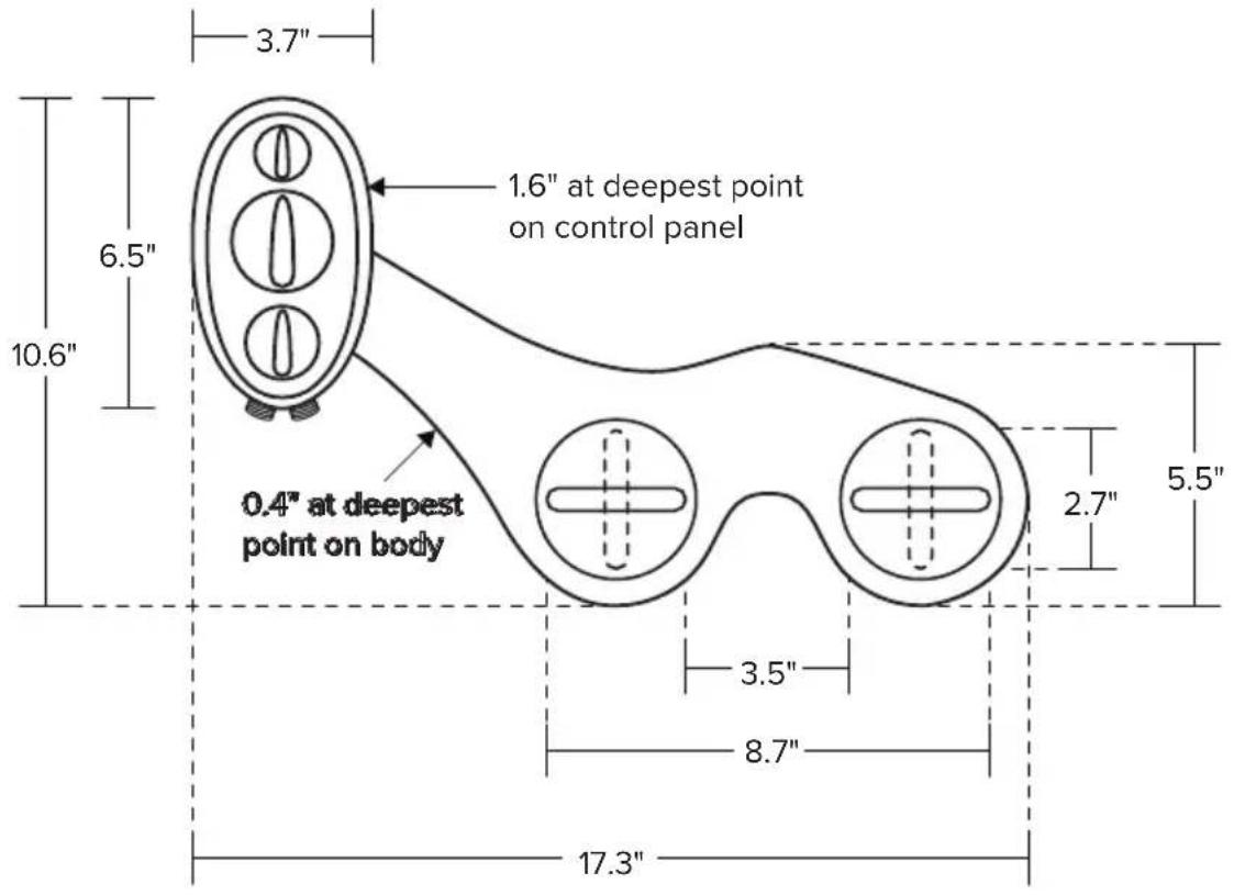
PRODUCT DIMENSIONS
text_image
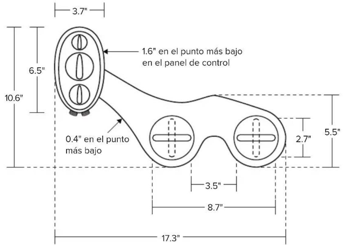
3.7" 6.5" 10.6" 1.6" at deepest point on control panel 0.4" at deepest point on body 2.7" 5.5" 3.5" 8.7" 17.3"PRODUCT INSTALLATION
BEFORE INSTALLATION
IMPORTANT
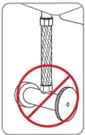
Please be advised that the provided T-Valve should be installed at the Fill Valve under the toilet tank, and NOT at the cold water supply coming from the wall.
If you do not have access to the Fill Valve under the toilet tank, contact Brondell Customer Service at 888.542.3355. We may be able to guide you through the process.
text_image
Diagram showing a pipe fitting with a prohibition symbol indicating no movement or force, featuring a circular diagram of a valve.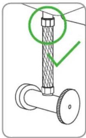
natural_image
Technical diagram of a pipe fitting with a green checkmark indicating a detail (no text or symbols present)Check the size of the hot water supply connection (most likely under the sink/wash basin). This needs to be a 3/8" connection for our T-valve to install.
Note: if the connection is a 1/2" connection, you will need to purchase the following reducing adapter available online and at many plumbing hardware stores: Reducing Adapter, 1/2" Female NPT x 3/8" Male Compression.
Check Water Supply Line
Check the water supply line that connects the toilet tank fill valve to the water shutoff valve at the wall. If it is a rigid pipe, you will need to purchase a flexible water supply hose to replace it before installing the SouthSpa. The length of the hose may vary, and the top connection size should be 7/8" Ballcock to connect to the T-valve that you will install under the toilet tank, and the bottom connection will vary (most common are 3/8" and 1/2" female compression).
PRODUCT INSTALLATION (cont.)
CONNECTING THE COLD WATER SUPPLY
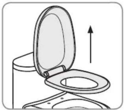
- Remove existing toilet seat
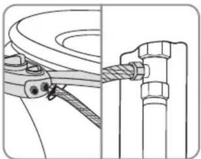
a. Lift hinge covers and use flathead or Phillips head screwdriver to remove the mounting bolts. Alternatively, you may need to loosen mounting bolts underneath the seat.
b. Remove the toilet seat and set the seat, mounting bolts and hardware aside.
- Turn off water supply valve and flush toilet
a. Turn off water supply at the wall to stop flow of water.
b. Flush toilet and hold down handle to completely empty toilet tank.
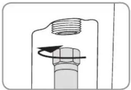
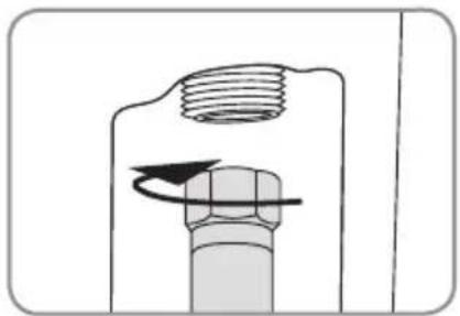
c. Disconnect water supply hose from the fill valve under the toilet tank.
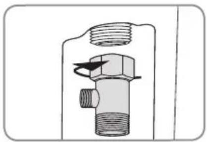
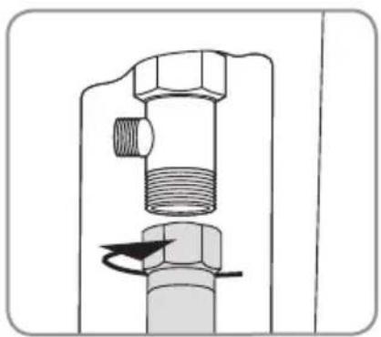
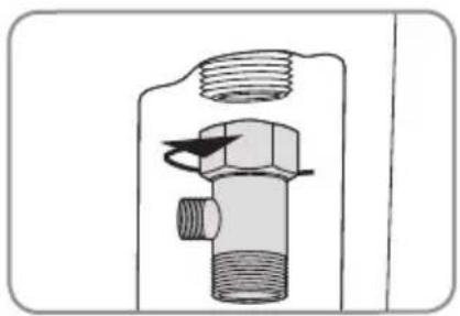
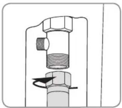
- Connect 7/8" T-Valve to Water Supply Line and Fill Valve Under Toilet Tank.
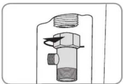
a. Install the 7/8" T-valve with one or both of the rubber washers to the incoming water connection on the bottom of your toilet tank.
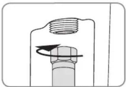
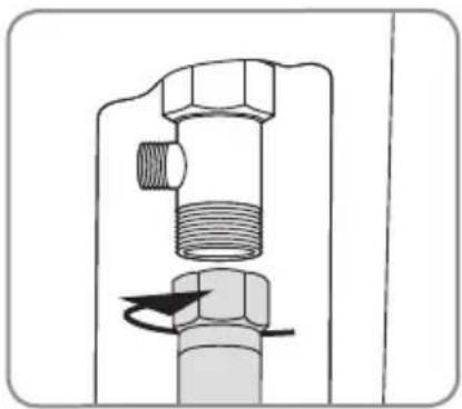
b. Connect the cold water supply line coming from the wall to the bottom of the T-valve.
natural_image
Diagram of a toilet with an open lid and upward arrow indicating motion (no text or symbols)Step 1b
natural_image
Diagram of a mechanical component with threaded shaft and bolt, showing rotational motion (no text or symbols)Step 2c
natural_image
Technical illustration of a mechanical valve assembly (no text or symbols)Step 3a
natural_image
Mechanical assembly diagram showing a valve with threaded shaft and bolt, no text or symbols presentStep 3b
CONNECTING THE COLD WATER SUPPLY (cont.)
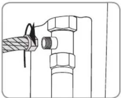
- Connect Bidet Hose to T-Valve
a. Connect one end of the braided metal bidet hose to the remaining open side of the installed T-valve.
natural_image
Technical line drawing of a mechanical joint or connector assembly (no text or symbols)Step 4a
IMPORTANT
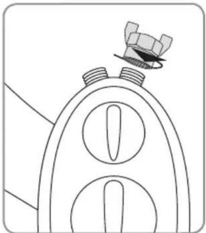
If you are only connecting the cold water supply, you must install the Hot Water Supply Cap
(provided - see Page 3) over the hot water connection on your SouthSpa (see diagram).
Failure to connect or cap the hot water supply will result in leaking during use.
After installing hot water cap, proceed to "Installing the Bidet Attachment" on Page 10.
If you wish to also connect your hot water supply, then proceed to "Connecting the Hot Water Supply" on Page 8.
natural_image
Line drawing of a mechanical component with threaded ends and a small inset showing a pin (no text or symbols)PRODUCT INSTALLATION (cont.)
CONNECTING THE HOT WATER SUPPLY
- Connect the hot water supply
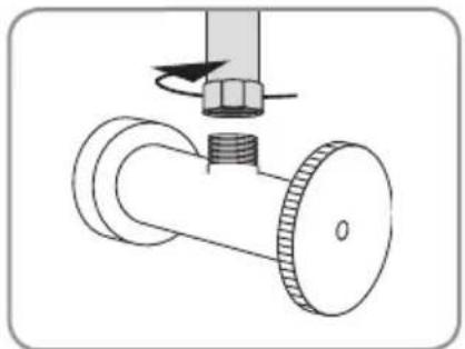
a. Locate the hot water supply line in your bathroom under your sink/washbasin and turn the water supply valve all the way off.
b. Drain the hot water line by turning on the sink tap on the hot setting until no more water comes out.
c. Disconnect hot water supply hose to sink from shut off valve. You may have to use a 3/8" compatible wrench or a similar tool (not supplied).
Note: there may be some residual water in the hose, use a small container or towel to catch any residual water.
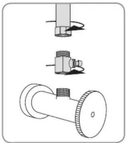
- Install the Hot Water 3/8" T-valve and the small rubber washers as needed onto the hot water shut off valve under the sink.
- Reconnect hot water supply line to open end (top) of T-valve.
natural_image
Technical line drawing of a valve assembly with a bolt and nut (no text or symbols)Step 1c
natural_image
Technical line drawings of three mechanical components: a bolt, a valve, and a flanged pipe fitting (no text or symbols)Steps 2 and 3
CONNECTING THE HOT WATER SUPPLY (cont.)
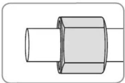
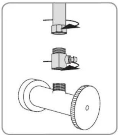
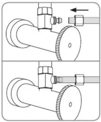
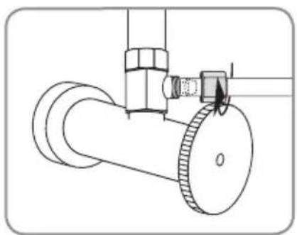
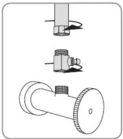
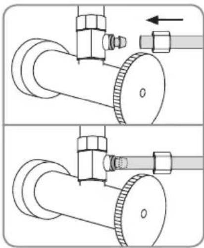
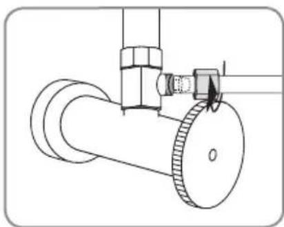
- If it hasn't been removed already, unscrew the Pressure Cap covering the Pressure Connector.
a. Slide the Pressure Cap over the open end of the of Hot Water Flex Tubing with the inside threads facing towards the open end.
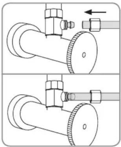
b. Push the Hot Water Flex Tubing over the Pressure Connector.
IMPORTANT: Be sure to slide the Hot Water Flex Tubing over the Pressure Connector until the tubing slides past the "lip" of the pressure connector and it cannot go any further.
c. Slide the Pressure Cap down until the cap meets the Pressure Connector. Screw the Cap onto the T-Valve until secure and tight.
Caution: Do not over-tighten the Pressure Cap. You will risk damaging the tubing.
natural_image
Technical line drawing of a mechanical connector or fitting (no text or symbols)Step 4a
natural_image
Technical illustration of a pipe valve assembly with two views (top and bottom) showing internal components and directional arrows (no text or symbols)Step 4b

natural_image
Technical line drawing of a mechanical valve assembly (no text or symbols)Step 4c
PRODUCT INSTALLATION (cont.)
INSTALLING THE BIDET ATTACHMENT
- Install Bidet Attachment on Toilet
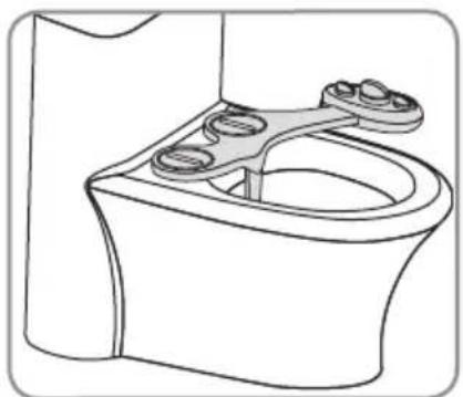
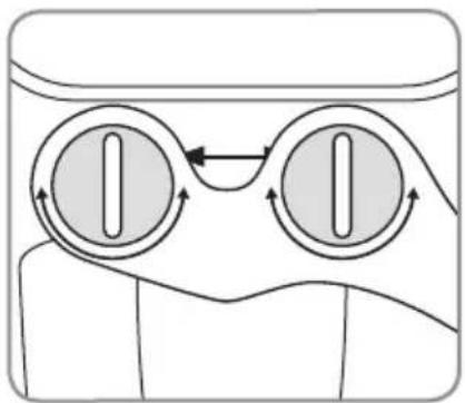
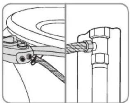
a. Place bidet attachment on the toilet so the nozzles are as close to the back of the toilet bowl as they will go. This will vary by toilet.
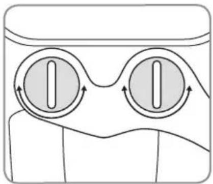
b. Make sure the adjustable brackets line up with the holes in the toilet fixture. You may need to rotate the adjustable brackets to line up with the bolt holes properly.
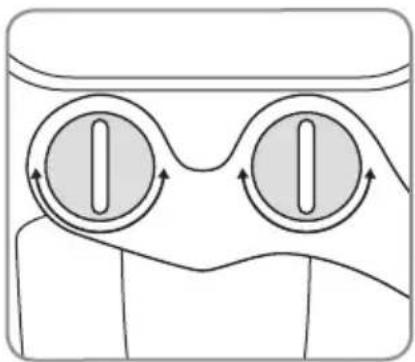
c. Replace the toilet seat on top of bidet attachment and secure using original toilet seat hardware. Make sure to tighten so that the bidet attachment and seat do not move.
- Connect Cold Water Bidet Hose to Bidet Attachment
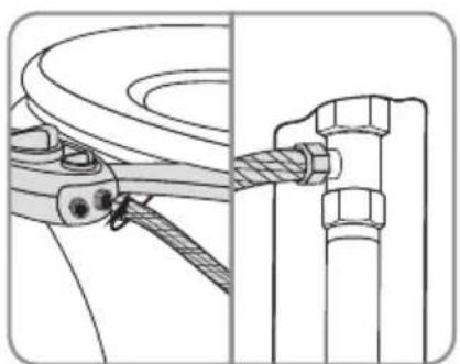
a. Connect the open end of bidet hose to the Cold connection on the back of the bidet attachment.
Note: If you have already installed the Hot Water Supply Cap over the hot water supply on your SouthSpa, Skip to Step 4 on Page 11. Otherwise continue with the installation at the top of Page 11.
natural_image
Line drawing of a toilet with two circular components attached (no text or symbols)Step 1a
natural_image
Diagram of a mechanical or electrical component with two circular components and directional arrows indicating motion (no text or symbols)Step 1b
natural_image
Technical line drawing of a mechanical assembly with rope and bolted joint (no text or symbols)Step 2a
INSTALLING THE BIDET ATTACHMENT (cont.)
- Connect Hot Water Supply to Bidet Attachment
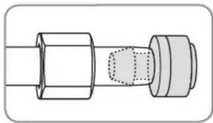
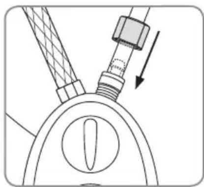
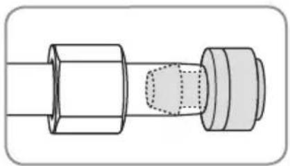
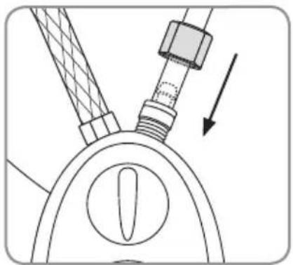
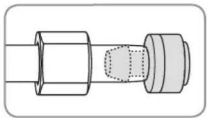
a. Slide the Pressure Cap over the open end of the of Hot Water Flex Tubing with the inside threads facing towards the open end.
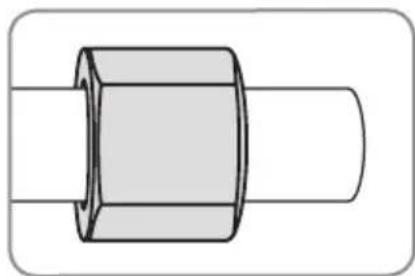
b. Push the Pressure Connector into the open end of the of Hot Water Flex Tubing with the washer facing out.
IMPORTANT: Be sure to slide the Hot Water Flex Tubing over the Pressure Connector until the tubing slides past the "lip" of the pressure connector and it cannot go any further.
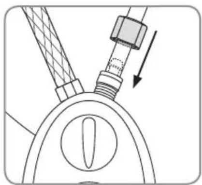
c. Hold the Pressure Connector up against the hot water inlet on the bidet attachment. Slide the Pressure Cap along the tubing and screw the Cap onto the hot water inlet until the Pressure Connector is secure.
- Turn on Water Supply & Check for Leaks
a. Open the hot and cold water supply valves slowly and check for leaks.
b. Wait 5-10 minutes, check again and if there are no leaks continue.
Note: If there is any leaking, check all rubber washers and make sure all water connections are tight and secure. If necessary, you can use plumbers tape for any leaking connections.
natural_image
Simple line drawing of a hexagonal bolt head with a flanged shaft (no text or symbols)Step 3a
natural_image
Technical line drawing of a mechanical connector or fitting (no text or symbols)Step 3b
natural_image
Technical diagram of a mechanical assembly with a bolt and threaded rod, showing no text or symbolsStep 3c
PRODUCT OPERATION
USING THE SOUTHSPA
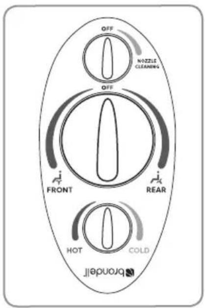
If only connected to cold water, make sure that the temperature dial on the bidet attachment is turned as far as it can go towards "COLD" setting for best pressure adjustability.
To adjust water temperature (when both hot and cold water are connected), turn temperature dial slowly towards “HOT” until the desired temperature is reached.
Note: There may be a delay in the warm water reaching the bidet attachment as the cold water in your pipes clears and is replaced with hot water (similar to the delay when you turn your faucet on).
Tip: For a quick and easy way to get warm water to the bidet, run the "Nozzle Cleaning" function with the warm water turned on for a short time until the water heats up, then use as normal.
text_image
OFF NOZZLE CLEANING OFF FRONT REAR HOT COLD BRONDELLFor the general bidet wash function, turn the dial towards either the Front (also known as the Feminine) wash position, or the Rear (also known as the Posterior) wash position.
- The further the dial is turned, the higher the water pressure will be.
• To lower the water pressure, turn the dial back towards the center.
To clean the bidet nozzle, turn the control dial towards the "Nozzle Cleaning" position and water will wash over the nozzles.

WARNING: Risk of scalding. High water temperature can cause severe burns. Be sure to set the water temperature for your hot water heater at or below 120^ F ( 49^ C) and use extreme caution when mixing hot and cold water during use. Brondell is not liable for any misuse of product or failure to use caution when connecting to hot water.
NOZZLE POSITIONING
The nozzles can be easily adjusted by gently pulling the end of the nozzle forward or backwards. Once desired position is set, the nozzle will remain in that position until manually moved.
MAINTENANCE
CLEANING THE SOUTHSPA
To clean the nozzles, gently pull down on the head of the nozzle, and use a toothbrush or soft cloth and mild detergent (such as dish soap). You may also unscrew the nozzle tip cap for a more thorough cleaning or use a toothpick if any nozzle holes are plugged with hard water buildup. When cleaning, be careful not to drop or flush the nozzle cap.
To clean the bidet, use a mild cleaner such as Simple Green or Windex spray to clean the SouthSpa. Do not scrub or use harsh, abrasive products to clean the SouthSpa, which may scratch the product.
SHORT TERM NON-USE
If the product will not be used for more than a few weeks, you may consider shutting the water supply off at the wall for extra precaution.
WARRANTY
Brondell products are backed by some of the most comprehensive warranties in the industry.
Brondell warrants that all products (excluding consumable items) shall be free from defects in material and workmanship under normal use and service.
SouthSpa LH-10, LH-12, LH-20, LH-22 Residential One-Year Limited Warranty
100% Coverage of all parts and labor for the entire product for the first year from original date of purchase.
SouthSpa LH-10, LH-12, LH-20, LH-22 Commercial Warranty
Warranty period 1 year from original purchase date for all Brondell products. Warranties may not apply to products that are used for heavy commercial, hospital, or other high use non-residential applications.
Exclusions and Limitations
- BRONDELL warrants its products to be free from manufacturing defects under normal use and service. This warranty is extended only to the ORIGINAL PURCHASER.
- BRONDELL's obligations under this warranty are limited to repairs or replacement, at BRONDELL's option, of products or parts found to be defective, provided that such products were properly installed and used in accordance with instructions. BRONDELL reserves the right to make such inspections as may be necessary in order to determine the cause of the defect. BRONDELL will not charge for labor or parts in connection with warranty repairs for the first three years from date of purchase on all products except those that may be subject to commercial use limitations.
-
BRONDELL is not responsible for the cost of removal, return (shipping) and/or re-installation of products. This warranty does NOT apply to:
-
Damage or loss which occurs during shipment.
- Damage or loss sustained through any natural or man-made causes beyond the control of BRONDELL, including but not limited to fire, earthquake, floods, etc.
- Damage or loss resulting from sediments or foreign matter contained in a water system.
- Damage or loss resulting from negligent or improper installation including installation of a unit in a harsh or hazardous environment.
- Damage or loss resulting from removal, improper repair, modification of the product, or improper maintenance including damage caused by chlorine or chlorine related products
-
Damage or loss resulting from electrical surges, electrical outages, lightning strikes, or other acts which are not the fault of Brondell or which the Product is not specified to tolerate.
-
This warranty gives you specific legal rights. You may have other rights which vary from state to state.
THIS WRITTEN WARRANTY IS THE ONLY WARRANTY MADE BY BRONDELL. REPAIR OR REPLACEMENT AS PROVIDED UNDER THIS WARRANTY SHALL BE THE EXCLUSIVE REMEDY AVAILABLE TO THE PURCHASER. BRONDELL SHALL NOT BE RESPONSIBLE FOR LOSS OF USE OF THE PRODUCT OR FOR OTHER INCIDENTAL, SPECIAL, FOR CONSEQUENTIAL DAMAGES OR EXPENSES INCURRED BY THE PURCHASER OR FOR LABOR OR OTHER COSTS DUE TO INSTALLATION OR REMOVAL OR COSTS OF REPAIRS BY OTHERS, OR FOR ANY OTHER EXPENSE NOT SPECIFICALLY STATED ABOVE. EXCEPT TO THE EXTENT PROHIBITED BY APPLICABLE LAW, ANY IMPLIED WARRANTIES, INCLUDING THAT OF MERCHANTABILITY, ARE EXPRESSLY LIMITED TO THE DURATION OF THIS WARRANTY. SOME STATES DO NOT ALLOW LIMITATIONS, SO THE ABOVE LIMITATION AND EXCLUSION MAY NOT APPLY TO YOU.
How to Obtain Service
To obtain repair service under this warranty, you must contact an authorized BRONDELL Service Center to obtain an RMA (Return Merchandise Authorization) number. Proof of purchase in the form of a copy of the original receipt must accompany the returned unit for the warranty to be valid. Take or ship the unit pre-paid to the closest Brondell authorized service center along with the RMA number and proof of purchase.
To obtain the RMA number and locate the BRONDELL Service Center location nearest you, please call 1-888-542-3355.
brondell®
a healthy home experience
CONTACT:
Brondell, Inc.
PO Box 470085
San Francisco, CA 94147-0085
Phone: 1-888-542-3355
Email: support@brondell.com
Web: www.brondell.com
For questions, contact Brondell Customer Service: 1-888-542-3355
MANUFACTURED BY:
Brondell, Inc.
PO Box 470085
San Francisco, CA 94147-0085
Please retain receipt records for any warranty claims.
ÍNDICE
natural_image
Technical line drawing of a mechanical clamp or lever mechanism (no text or symbols)natural_image
Simple line drawing of an arched pipe or tube with mesh pattern (no text or symbols)natural_image
Simple line drawing of a coiled spring or rope (no text or symbols)DIMENSIONES DEL PRODUCTO
text_image
Diagram showing a mechanical device with a red prohibition symbol indicating no movement or force.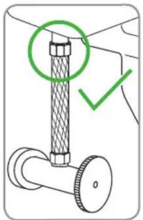
natural_image
Diagram of a pipe fitting with a green circular annotation highlighting a section, and a green checkmark indicating action (no text or symbols present)natural_image
Line drawing of a toilet with an open lid and upward arrow indicating rotation (no text or symbols)Etapa 1b
natural_image
Diagram of a mechanical component with threaded end and bolted joint, showing rotational motion (no text or symbols)Etapa 2c
natural_image
Technical line drawing of a mechanical valve assembly (no text or symbols)Etapa 3a
natural_image
Mechanical diagram showing a valve assembly with threaded shaft and bolt, no text or symbols presentEtapa 3b
natural_image
Technical line drawing of a pipe fitting with threaded end (no text or symbols)Etapa 4a
IMPORTANTE
natural_image
Pure technical line drawing of a mechanical component with no text or symbolsnatural_image
Technical line drawing of a mechanical valve assembly with a bolt and threaded shaft (no text or symbols)Etapa 1c
natural_image
Technical line drawings of three mechanical components: a bolt, a nut, and a valve (no text or symbols present)Etapas 2 y 3
natural_image
Technical line drawing of a mechanical connector or fitting (no text or symbols)Etapa 4a
natural_image
Technical illustration of a pipe fitting with two views showing mechanical assembly (no text or symbols)Etapa 4b
natural_image
Technical line drawing of a mechanical valve assembly (no text or symbols)Etapa 4c
INSTALAR EL ACCESORIO BIDÉ
natural_image
Line drawing of a toilet with two circular components attached (no text or symbols)Etapa 1a
natural_image
Diagram of two circular objects with directional arrows indicating flow or movement (no text or symbols)Etapa 1b
natural_image
Technical line drawing of a mechanical assembly with no visible text or symbolsEtapa 2a
natural_image
Pure technical line drawing of a mechanical component (no text or symbols)Etapa 3a
natural_image
Technical line drawing of a mechanical connector or fitting with hexagonal ends and a dashed-line section (no text or symbols)Etapa 3b
natural_image
Technical diagram of a mechanical assembly with a threaded component and directional arrow (no text or symbols)Etapa 3c
text_image
OFF NOZZLE CLEANING OFF FRONT REAR HOT COLD BRONDELLLIMPIANDO EL SOUTHSPA
a healthy home experience
CONTACTAR:
Brondell, Inc.
PO Box 470085
San Francisco, CA 94147-0085
Phone: 1-888-542-3355
Email: support@brondell.com
Web: www.brondell.com
CARACTÉRISTIQUES DU PRODUIT
INSTALLATION DU PRODUIT
Avant l'installation ...... Page 35
CARACTÉRISTIQUES DU PRODUIT
CARACTÉRISTIQUES DU PRODUIT
natural_image
Technical line drawing of a mechanical clamp or lever component (no text or symbols)natural_image
Line drawing of an arched pipe or tube with mesh pattern (no text or symbols)natural_image
Simple line drawing of a coiled spring or rope (no text or symbols)CARACTÉRISTIQUES DU PRODUIT (suite)
DIMENSIONS DU PRODUIT
INSTALLATION DU PRODUIT
AVANT L'INSTALLATION
IMPORTANT
text_image
Diagram showing a mechanical assembly with a red prohibition symbol over a gear mechanism, indicating no movement or force.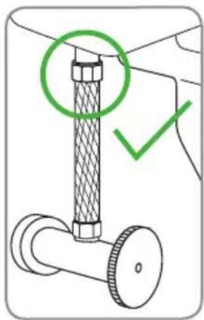
text_image
Diagram showing a mechanical assembly with a green circle highlighting a component and a green checkmark indicating selection.INSTALLATION DU PRODUIT (suite)
CONNECTER L'ALIMENTATION DE L'EAU FROIDE
natural_image
Diagram of a toilet with an open lid and upward arrow indicating motion (no text or symbols)Étape 1b
natural_image
Diagram of a mechanical component with threaded end and bolted joint, showing rotational motion (no text or symbols)Étape 2c
natural_image
Technical line drawing of a mechanical valve assembly (no text or symbols)Étape 3a
natural_image
Technical diagram of a mechanical valve assembly with threaded shaft and hexagonal base (no text or labels)Étape 3b
CONNECTER L'ALIMENTATION DE L'EAU FROIDE (suite)
natural_image
Technical line drawing of a pipe fitting with threaded end (no text or symbols)Étape 4a
IMPORTANT
natural_image
Simple line drawing of a mechanical component with no text or symbolsINSTALLATION DU PRODUIT (suite)
CONNECTER L'ALIMENTATION DE L'EAU CHAUDE
natural_image
Technical line drawing of a mechanical valve assembly with a bolt and nut (no text or symbols)Étape 1c
natural_image
Technical line drawings of three mechanical components: a bolt, a nut, and a valve (no text or symbols)Étape 2 et 3
CONNECTER L'ALIMENTATION DE L'EAU CHAUDE (suite)
natural_image
Technical line drawing of a mechanical connector or fitting (no text or symbols)Étape 4a
natural_image
Technical illustration of a pipe fitting with two views showing mechanical assembly (no text or symbols)Étape 4b
natural_image
Technical line drawing of a mechanical valve assembly (no text or symbols)Étape 4c
INSTALLATION DU PRODUIT (suite)
INSTALLATION DU BIDET
natural_image
Line drawing of a toilet with two circular components attached (no text or symbols)Étape 1b
natural_image
Diagram of two circular objects with directional arrows indicating flow or movement (no text or symbols)Étape 1c
natural_image
Technical line drawing of a mechanical assembly with rope and bolts (no text or symbols)Étape 2a
INSTALLATION DU BIDET (suite)
natural_image
Pure technical line drawing of a mechanical component with no text or symbolsÉtape 3a
natural_image
Technical line drawing of a mechanical connector or fitting with hexagonal ends and a dashed-line section (no text or symbols)Étape 3b
natural_image
Technical diagram of a mechanical assembly with a valve and adjustment lever (no text or symbols)Étape 3c
FONCTIONNEMENT DU PRODUIT
UTILISATION DU SOUTHSPA
text_image
OFF NOZZLE CLEANING OFF FRONT REAR HOT COLD BRONDELLPLACEMENT DE LA BUSE
Exclusions and Limitations
a healthy home experience
COORDONNÉES:
Brondell, Inc.
PO Box 470085
San Francisco, CA 94147-0085
Phone: 1-888-542-3355
Email: support@brondell.com
Web: www.brondell.com