Millbrook K-5264 - Water dispenser KOHLER - Free user manual and instructions
Find the device manual for free Millbrook K-5264 KOHLER in PDF.

User questions about Millbrook K-5264 KOHLER
0 question about this device. Answer the ones you know or ask your own.
Ask a new question about this device
Download the instructions for your Water dispenser in PDF format for free! Find your manual Millbrook K-5264 - KOHLER and take your electronic device back in hand. On this page are published all the documents necessary for the use of your device. Millbrook K-5264 by KOHLER.
USER MANUAL Millbrook K-5264 KOHLER
natural_image
Line drawing of a boat hull with handle and side panel (no text or symbols)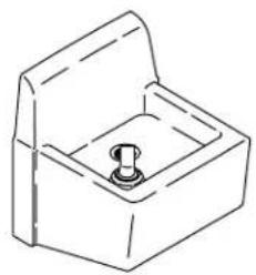
natural_image
Line drawing of a mechanical component with a central bolt and housing (no text or symbols)Mproduct numbers are for Mexico (i.e. K-12345M)
• Various Carpentry Tools
BeforeYouBegin

CAUTION: Riskofpersonalinjury. Handle with care. Vitreous china can break or chip if the product is handled carelessly.
□ Observe all local plumbing and building codes.
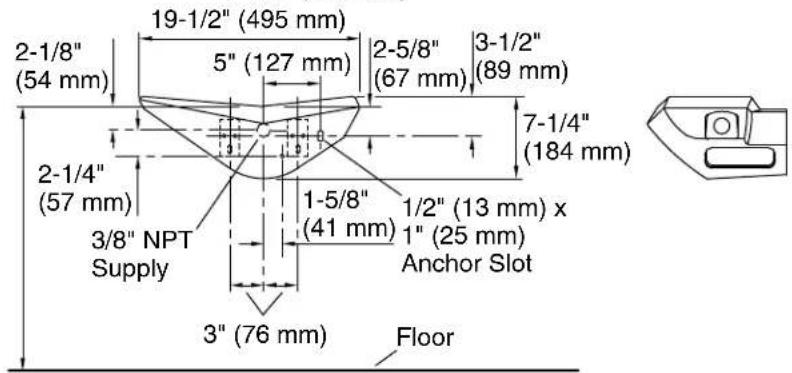
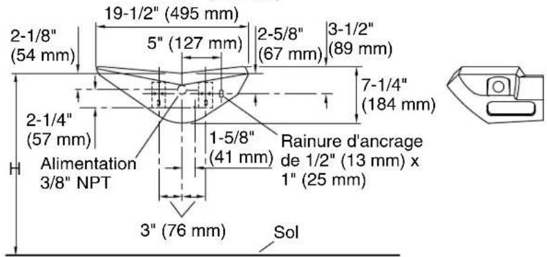
Roughing-InforK-5250
- The distance between the rim and the floor (dimension H) is 30" (762 mm) for grade schools and 36" (914 mm) to 44" (1118 mm) for other buildings.
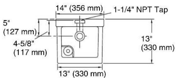
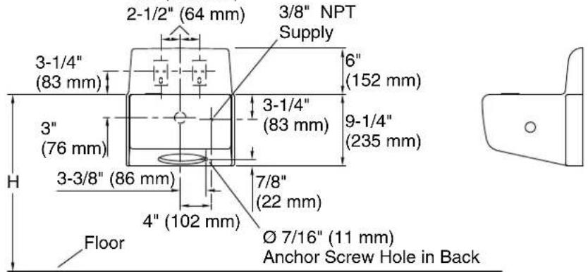
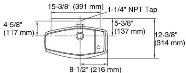
Roughing-InforK-5264
- The distance between the rim and the floor (dimension H) is 30" (762 mm) for grade schools and 36" (914 mm) to 44" (1118 mm) for other buildings.
1. PreparetheSite
NOTE: Be sure to install sufficient backing to support the wall hangers and anchor bolt.
☐ Rough-in the supply and drain piping according to the roughing-in.
☐ Temporarily install a capped length of 1-1/4" and 3/8" pipe to the drain and supply to extend a minimum of 2" (51 mm) beyond the finished wall.

2. InstalltheDrain
☐ Remove the temporary 3/8" pipe previously installed into the supply fitting.
☐ Remove the 1-1/4" pipe installed to the drain fitting.
☐ Install a 3/8" nipple for the supply to extend approximately 7/16" (11 mm) from the finished wall.
NOTE: If the tubing is used for supply, a male threaded adapter must extend approximately 7/16" (11 mm) from the finished wall.
□ Assemble the water stop onto the nipple.
☐ Ensure that the screwdriver slot on the water stop is angled at 45^ , and that it is facing toward the bottom access.
☐ Ensure that the water stop inlet and outlet are parallel to the floor.
3. InstalltheDrinkingFountain
☐ Measure the distance between the finished wall and the center of the drinking fountain outlet.
□ Remove the temporary capped nipple.
☐ Replace the temporary nipple with a nipple that will position the trap inlet directly under the drinking fountain outlet.
☐ Install the two provided wall hangers to the wall, as shown in the roughing-in diagram. Secure the hangers by the center hole only.
InstalltheDrinkingFountain(cont.)
☐ Install the trap to the nipple. Position and level the fountain onto the hangers.
NOTE: The hangers may have to be repositioned. Due to dimensional variations with vitreous china products, the hangers may have to be raised or lowered slightly so that there is 3/16" (5 mm) from the bottom of the drinking fountain outlet to the face of the trap inlet.
☐ Using screws, secure the two hangers to the backing through the remaining two holes in the hanger.
☐ Through the side access, mark the center of the 1/2" (13 mm) x 1" (25 mm) anchoring slot located on the right-hand back wall of the fountain.
□ Remove the fountain from the hangers and install the anchoring stud.
NOTE: The machine threaded portion of the anchoring stud should extend approximately 5/8" (16 mm) from the finished wall. The stud must be centered in the slot.
4. InstalltheStrainer
□ Apply a bead of plumbers putty or other sealant around the underside of the strainer body flange according to the manufacturer's instructions.
☐ Insert the strainer body into the fountain drain hole.
☐ From the underside of the drinking fountain, slide the tapered gasket onto the strainer body, making sure that the tapered side is facing up.
☐ Position the fountain onto the hangers so that the anchoring stud and the opening of the slot line up.
☐ Line up the strainer body with the trap, and thread the strainer body securely onto the trap.
NOTE: The fountain must be supported by the hangers only. Do not position the drain after it has been tightened into the trap, or the seal may be broken.
5.SecuretheFixture
CAUTION: Riskofpersonalinjury. Overtightening can cause vitreous china to break or chip.
☐ Place the washer and cap nut over the anchoring stud, and carefully tighten to secure the drinking fountain.
☐ From the bottom of the access, install the copper supply tube with the compression fitting between the stop and control valve.
□ Connect the straight end of the tube to the stop, then connect the angled end of the supply tube to the control valve until both are hand-tight.
□ Secure both nuts with a wrench.
NOTE: The copper supply connection may be bent slightly to fit.
☐ Snap the strainer plate into the strainer body. If necessary, adjust the drinking fountain head so that the arc of the water is parallel to the wall.
6. InstalltheCoverPlates
□ Check for leaks.
□ Install the cover plates to the bottom access openings.
7. Complethethel Installation
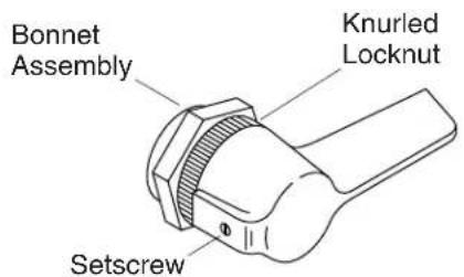
☐ When this drinking fountain is installed with a water cooler, jam the knurled locknut against the bonnet assembly to prevent continuous flow.
☐ The lever handle has been adjusted at the factory so that the blade is parallel to the floor. If additional adjustment is required, remove the setscrew with a 3/32" hex wrench.
□ Pull the handle straight off. Donottwistthehandle.
☐ Reverse this procedure to reinstall the handle.