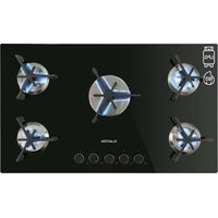
Trifecta 5 - Cooker Klarstein - Free user manual and instructions
Find the device manual for free Trifecta 5 Klarstein in PDF.


User questions about Trifecta 5 Klarstein
0 question about this device. Answer the ones you know or ask your own.
Ask a new question about this device
Download the instructions for your Cooker in PDF format for free! Find your manual Trifecta 5 - Klarstein and take your electronic device back in hand. On this page are published all the documents necessary for the use of your device. Trifecta 5 by Klarstein.
USER MANUAL Trifecta 5 Klarstein
text_image
QR code image containing encoded data, no visible human-readable textINHALT
text_image
Warning sign with exclamation mark inside a triangleWARNUNG
Explosionsgefahr
natural_image
Line drawing of a hand holding a ball bearing, with no text or symbols presenttext_image
Warning sign with exclamation mark inside a triangleWARNUNG
text_image
Exploded view diagram of a refrigerator with numbered parts for identification1 Topfträger
2 Brennerdeckel
3 Verteiler
4 Glas
5 Brenner
6 Thermoelement
7 Zündstift
8 Gasleitung
9 Brennerhalterung
10 Schutz
11 Zünder
12 Gehäuse
13 Gummifüße
14 Kabelbox
15 Kabel 20 Ventil
text_image
Exploded view diagram of a refrigerator with numbered parts for identification1 Topfträger
2 Wasserschale
3 Brennerdeckel
4 Verteiler
5 Glas
6 Brenner
7 Thermoelement
8 Zündstift
9 Gasleitung
10 Brennerhalterung
11 Aluminiumleitung
12 Schutz
13 Gehäuse
14 Gummifüße
15 Kabelbox
16 Kabel
17 Wasserschale
18 Brennerdeckel
19 Verteiler
text_image
Exploded view diagram of a device with numbered parts, likely for assembly or manufacturing purposes.text_image
Exploded view diagram of a device with numbered parts and internal components labeled in Chinese.text_image
Exploded view diagram of a device with numbered parts and component layoutstext_image
Exploded view diagram of a device with numbered parts and labeled components, including a central display case.1 Topfträger
2 Topfträger
3 Brennerdeckel
4 Verteiler
5 Wasserschale
6 Brennerdeckel
7 Verteiler
8 Wasserschale
9 Glas
10 Thermoelement
11 Zündstift
12 Brenner
13 Thermoelement
14 Zündstift
15 Brenner
16 Brennerhalterung
17 Brennerhalterung
18 Zünder
19 Gehäuse
20 Gummifüße
21 Kabelbox
22 Kabel
23 Wasserschale
24 Brennerdeckel
25 Verteiler
26 Drehknopf
text_image
450mm 700mm 60mm 200m 500mmtext_image
Diagram showing three steps of a mechanical or electrical process with arrows indicating direction and cross marks, likely illustrating a procedure or control.| A B C D E | ||||
| 700 mm min | 100 mm min 20 | mm Lufteinlass | Luftauslass5 mm |
Ausschnitt
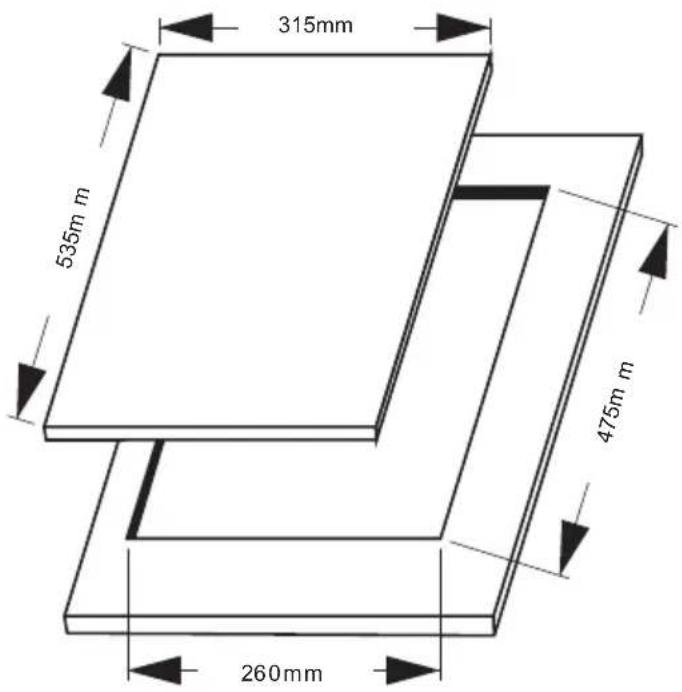
10039420 & 10035468
text_image
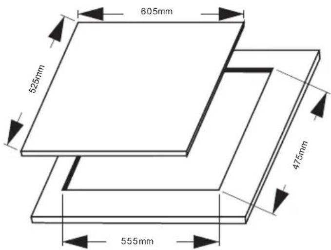
315mm 535m m 475m m 260mm10039421 & 10035469
text_image
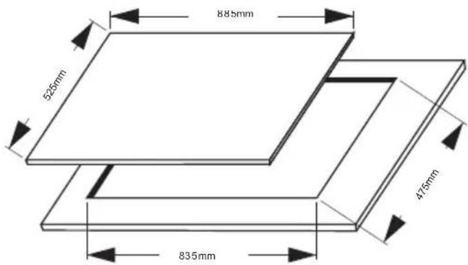
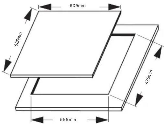
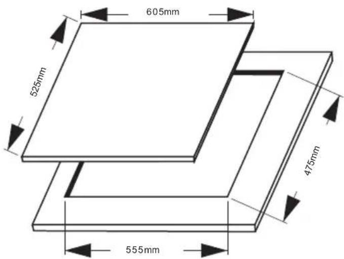
605mm 525mm 475mm 555mm10039422 & 10035470
text_image
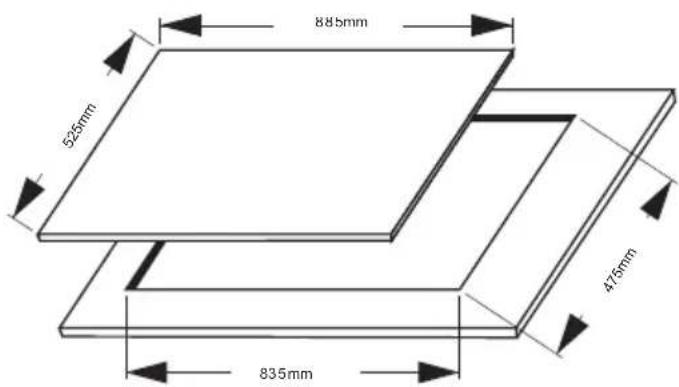
885mm 525mm 475mm 835mmtext_image
Warning symbol image with exclamation mark inside triangleVORSICHT
Member of Berlin Brands Group
Handwerkerstr. 11
15366 Dahlwitz-Hoppegarten
Deutschland
natural_image
Symbol of a trash bin crossed with a diagonal line, no text or numbers presentBerlin Brands Group UK Ltd
PO Box 1145
Oxford, OX1 9UW
United Kingdom
EU-PRODUKTDATENBLATT
Congratulations on purchasing this device. Please read the following instructions carefully and follow them to prevent possible damages. We assume no liability for damage caused by disregard of the instructions and improper use. Scan the QR code to get access to the latest user manual and more product information.

text_image
QR code image containing encoded data, no visible human-readable textCONTENTS
Technical Parameters 34
Safety Instructions 35
Connecting Gas Line 38
Operation 40
Cleaning and Maintenance 41
Troubleshooting 43
Exploded View 45
Installation 51
Disassembly 56
Disposal Considerations 57
Manufacturer & Importer (UK) 57
EU Product Data Sheet 58
TECHNICAL DATA
| Item number 1003 | 9420 10035468 10039421 | ||
| Number of burner 1 | 2 3 |
| Item number 1003 | 5469 10035470 10039422 | ||
| Number of burner 4 | 5 6 |
TECHNICAL PARAMETERS
| Product name | Gas Hob | CE2531-21PIN code 2531 CU-0100 | |||
| Item number | 10039420, 10035468, 10039421,10035469, 10035470, 10039422 | ||||
| Class of appliance | Class 3 | ||||
| Manufacturer | Chal-Tec GmbH Wallstr. 14 10179 Berlin | ||||
| G20 G30 | |||||
| Burner type Heat input (kW) Injector size (mm) Heat input (kW) | Injector size (mm) | ||||
| Rapid burner | 3,2 1,34 3,5 | 0,82 | |||
| Semi-rapid burner | 2,1 1,09 2,1 | 0,65 | |||
| Auxiliary burner | 1,15 0,8 1,15 0,5 | ||||
| Supply pressure | 20 mbar | 50 mbar | |||
| Country code | FR, IT, DK, IE, GB, GR, ES, PT, AT, FI,SE, CZ, EE, HU, LV, LT, SK, SI, IS, NO,CH, TR, BG, HR, RO, DE, LU, PL, NL | DE, AT, CH, LU, SK | |||
| Burner type | Rapid burner | Semi-rapid burner | Auxiliary burner |
| Number of burners | |||
| 10039420 | 1 | 0 | 0 |
| 10035468 | 1 | 1 | 0 |
| 10039421 | 1 | 1 | 1 |
| 10035469 | 1 | 1 | 2 |
| 10035470 | 1 | 1 | 3 |
| 10039422 | 1 | 1 | 4 |
SAFETY INSTRUCTIONS
Please take the time to read this instruction manual before installing or using the appliance. This instruction booklet must be kept with the appliance for any future reference. If the appliance is sold or transferred to another person, ensure the booklet is passed on to the new user.
- This appliance shall be installed in accordance with regulations in force and only used in a well ventilated space.
- Prior to installation, ensure that the gas and electrical supply complies with the type stated on the rating plate.
- Where this appliance is installed in marine craft or in caravans, it should not be used as a space heater.
- The gas pipe and electrical cable must be installed in such a way that they do not touch any parts or the appliance.
- This appliance should be installed by a qualified technician or installer.
- The adjustment conditions for this appliance are stated on the label or data plate.
- Remove all packaging before using the appliance.
- After unpacking the appliance, make sure the product is not damaged and that the connection cord is in perfect condition. Otherwise, contact the dealer before installing the appliance.
- The adjacent furniture and all materials used in the installation must be able to withstand a minimum temperature of 85 °C above the ambient temperature of the room it is located in, whilst in use.
- In the event of burner flames being accidentally extinguished, turn off the burner control and do not attempt to re-ignite the burner for at least one minute.
- The use of a gas cooking appliance results in the production of heat and moisture in the room in which it is installed. Ensure that the kitchen is well ventilated: keep natural ventilation holes open or install a mechanical ventilation device (mechanical extractor hood).
- Prolonged intensive use of the appliance may call for additional ventilation, for example opening of a window, or more effective ventilation, for example increasing the level of mechanical ventilation where present.
- Do not allow children to play near or with the appliance.
• The appliance gets hot when it is in use.
• Children should be kept away until it has cooled.
• This appliance is designed to be operated by adults.
• Children can also injure themselves by pulling pans or pots off the appliance.
- Children must not use the appliance! Persons with reduced physical, sensory or mental capabilities or those with a lack of experience and knowledge may only use the appliance if they are instructed on how to do so by a person responsible for their safety, or if they are supervised and understand the hazards associated with the use of the appliance.
- Only use the appliance for preparing food.
- Do not modify this appliance. Burner panel is not designed to operate from an external timer or separate remote control system.
- Do not use this appliance if it comes in contact with water. Do not operate this appliance with wet hands.
- The heating and cooking surfaces of the appliance become hot when they are in use, take all due precautions.
- Do not use large cloths, tea towels or similar as the ends could touch the flames and catch fire.
- Never leave the appliance unattended when cooking.
- Unstable or misshapen pans should not be used on the appliance as they can cause an accident by tipping or spillage.
- Do not use or store flammable materials in the storage drawer near this appliance.
- Perishable food, plastic items and aerosols may be affected by heat and should not stored above or below the appliance.
- Do not spray aerosols in the vicinity of this appliance while it is in operation.
- Ensure the control knobs are in the '●' position when not in use.
- This appliance is intended for domestic cooking only. It is not designed for commercial or industrial purposes.
- Use heat-resistant pot holders or gloves when handling hot pots and pans.
- When lifting the cookware, make sure that the pot holders do not come close to open flames.
- Take care not to let pot holders or gloves get damp or wet, as this causes heat to transfer through the material quicker with the risk of burning yourself.
- Only ever use the burners after placing pots and pans on them. Do not heat up any empty pots or pans.
- Never use plastic or aluminium foil dishes on the appliance.
- When using other electrical appliances, ensure the cable does not come into contact with the appliance surfaces of the cooking appliance.
- If you have any mechanical parts eg. an artificial heart in your body, consult a doctor before using the appliance.
- Do not use a tea towel or similar materials in place of a pot holder. Such cloths can catch fire on a hot burner.
- When using glass cookware, make sure it is designed for top plate cooking. If the surface is made of glass-cracked, switch off the appliance to avoid defeat electrocution.
- To minimise the possibility of burns, ignition of flammable materials and spillage, turn cookware handles toward the side or centre of the top plate without extending over adjacent burners.
• Always turn burner controls off before removing cookware. - Carefully watch foods being fried at a high flame setting.
• Always heat fat slowly and watch as it heats. - Foods for frying should be as dry as possible. Frost on frozen foods or moisture on fresh foods can cause hot fat to bubble up and over the sides of the pan.
- Never try to move a pan of hot fat, especially a deep fat fryer. Wait until the fat is completely cool.
CONNECTING GAS LINE
The gas connection between the gas meter and the cooker can be made of metal bellows or rubber hose for gas, and the length should not exceed 1.5 m. For kitchen appliances that require a sterilizer, oven, microwave oven, etc. underneath the cooker, metal bellows must be used and the connecting tube must be fixed.
Gas cookers that use LPG liquefied petroleum gas should be connected by gas rubber hose.
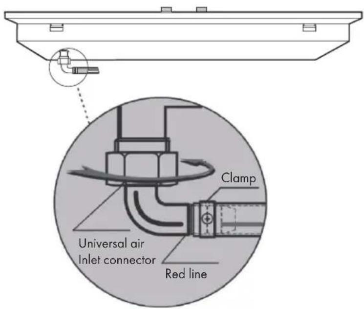
• The use of a rubber hose connection requires a universal air inlet connection.
- The two ends of the gas hose are connected to the cooker and the indoor gas valve (the inner diameter of the gas hose is 9.5 mm).
- Make sure that the gas hose is not squeezed, twisted or bent by other items. After the connection is completed, gas leak detection should be performed.
- Do not expose the gas hose to high temperatures.
- It is recommended that you perform a regular air tightness check on the gas cooker every year.
- Always check that the gas rubber hose is in good condition, with or without aging, cracks, and regular replacement.
text_image
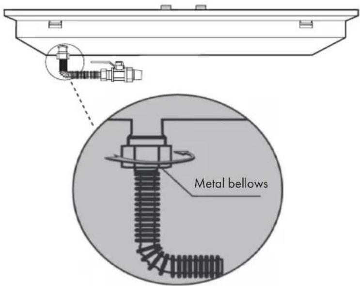
Clamp Universal air Inlet connector Red lineGas cookers using natural gas and artificial gas should be connected using metal bellows.
• Metal bellows meet the following requirements: CJ/T197-2010
- Please install in strict accordance with the installation method and procedure of the "Gas Stainless Steel Flexible Special Connection Pipe" package insert.
• Do not expose the gas hose to high temperatures.
• Gas leak detection should be performed after the connection is completed.
text_image
Metal bellowsImportant!
- The gas hose must be inserted outside the red wire of the universal air inlet connector and secured with a clamp!
- There must be a sealing rubber ring in the intake elbow and the gas connection pipe to be installed and used!.
Gas leakage detection
Soap water leakage detection:
Apply a soft brush to the joints with soapy water and open the gas valve to see if bubbles are generated. If there is air bubble, please close the gas valve immediately, adjust the leak connection and try again until no air bubbles are generated.
Installation for battery
The battery compartment cover is located on the lower right side of the front side of the product case. Please insert the supplied 1 or 2 section batteries correctly into the battery case according to the positive and negative indications. To ensure long-lasting ignition system, use a high-energy alkaline battery. If the ignition frequency is slowed down during use, please change the battery in time.
Installation for pan support, burner cap and burner
- Make sure that the knob, burner set and pan support are properly installed. Improper installation can seriously affect the normal use of the product and shorten the life of the product.
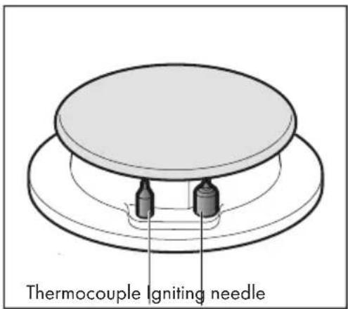
- When installing the burners, make sure that the burner mounting holes are inserted in the ignition pin and thermocouple. During installation, make sure that the stainless steel surfaces of the appliance are not scratched by the individual appliance components or that you accidentally break off the ignition pin. Damage caused in this way is not covered by the warranty.
OPERATION
Note: By using a thicker pan, it can improve heat distribution, especially when using a small fire. The larger the size of the pot is, the higher the efficiency of the hob will be. Whenever you want to leave the pot for a short time, please adjust flame to minimum setting. In this way, even if you are close to the hob for other operations, it can reduce the risk of burns, in the same time, it can save gas and reduce pollution.
When using large cookware, please ensure that the distance between the cookware and the surrounding combustibles should be at least 25 mm, and the distance between the knob and the cookware must be kept at least 50 mm.
Automatic ignition
- If the hob can be igniting automatically (pulse igniter): Press the control knob of the selected burner and turn counterclockwise to the maximum fire setting. When the control knob is held down, a spark is generated on all burners.
• The flame ignites. - Release the control knob.
- Turn the control knob to the desired setting position.
If no flame is produced, turn the control to the "Off" setting and repeat the above steps. This time hold down the control knob for a long time (up to 10 seconds).
Deflagration hazard
If the flame still does not ignite after 15 seconds, turn off the burner and open a nearby window or door. After waiting at least one minute, please try turning the burner on again.
Flame failure safety device
Some models may have a safety system (thermocouple) to prevent gas spills when the burner is accidentally turned off.
text_image
Thermocouple Igniting needle- Before using the appliance, make sure that the safety device has been activated.
- Switch on the appliance normally.
- Do not release the control knob after the flame is ignited, please continue to press firmly. Please hold the knob for 4 seconds.
Shutdown burner
Turn the corresponding control knob clockwise to the 0/OFF setting position.
Notes
- It is normal to hear a slight sizzle during the burner is working.
- For the first time of using, it is normal that there is smell. This is not a dangerous condition and does not indicate a malfunction. These phenomena will disappear on its own.
- The orange colour flame is normal. This is because there is dust or splashing liquid in the air.
- If the flame is accidentally blown out, turn the knob of the corresponding burner to the "Off" position. Wait at least one minute before you attempt to reignite the burner.
- After a few seconds of turning off the burner, an audible (hit) will sound. This is not a malfunction, but rather the safety device is no longer functioning.
- Keep the burner as clean as possible. If the spark igniter is dirty, it will not ignite normally. Regularly use a non-wire brush for cleaning. Please keep in mind that the spark igniter should not be subjected to violent impact.
CLEANING AND MAINTENANCE

text_image
Warning sign with exclamation mark inside a triangleWARNING
Danger of explosion
Before cleaning the gas hob, the indoor gas valve must be cut off and the gas cooker has been cooled. Do not disassemble the safety devices and airtight components of the gas hob during the cleaning process!
When disassembling the fire cover, please be careful not to hit the ignition needle to prevent the ceramic ignition needle from being cracked by external force.
Cleaning top panel and pan support
- Please clean and maintain the hob panel with soft gauze and soapy water (or special detergent).
- Do not use a granular detergent (decontamination powder), steel wool or sharp objects to clean the top panel or the water tray, otherwise it will easily cause surface scratches.
- Do not use acidic substances (lemonade, vinegar, etc.) to scrub the enamel surface such as the pan support.
Cleaning the burner cap
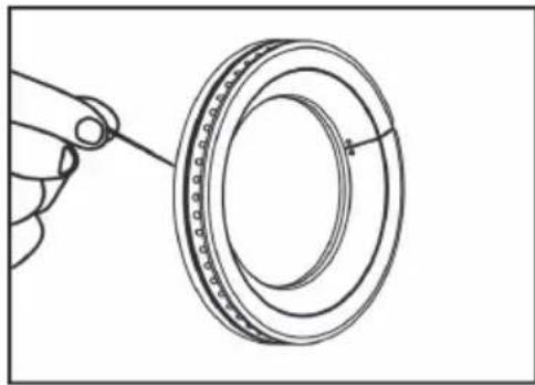
The surface of the burner cap and the fire hole are recommended to be cleaned at least once a month. In particular, if the flame is uneven or if there is no flame in the individual fire trough, please remove the burner cap and clean it. Use steel needle to remove the dirt and carbon deposit in the flame hole.
natural_image
Line drawing of a hand holding a ball bearing, with no text or symbols presentPlease do not flush the burner cap directly with water. Please make sure the burner cap is dry before using it again.
Cleaning the ignition needle and thermocouple
Please use a soft brush to clean the surface of the ignition needle and the thermocouple. Please do not bump the ignition needle when cleaning. After cleaning, please make sure all parts are dry, then install the hob, burning head and fire cover correctly according to the "Installation" instructions. Warranty will not cover the case if panel surface is scratches or the burner cap assembly is deformed due to improper installation.
TROUBLESHOOTING
| Problem | Cause Treatment | |
| Ignition electrode does not catch fire. | No battery, installation of battery is bad contact or reversed. | Reinstall correctly. |
| The burner is not installed in place. | Reinstall correctly. | |
| Improper position of ignition electrode and inner fire cover. | Adjust the distance between the ignition electrode and the inner fire cover to 3-4 mm. | |
| Ignition electrode is damp or dirty due to food spillage. | Dry the ignition electrode with a dry soft cloth. | |
| When the knob is released, the flame is extinguished. | The pressing pressure is not enough, the safety solenoid valve is not sucking. | Re-ignite and press the knob in place before you can let go. |
| Pulse igniting, but fail or igniting difficultly. | Gas valve is not open or not fully open. | Confirm that the gas valve is fully open. |
| There is air in the gas pipe. | Repeated ignition operation until succeed. | |
| Burner, burner cap, etc. are not installed correctly. | Reinstall correctly | |
| The fire hole is blocked on the burner cap and the gas cannot flow normally. | Unblock and clean the dirt in the fire hole. | |
| Ignition electrode is damp or dirty due to food spillage. | Dry the ignition electrode and remove dirt. | |
| Gas connection pipe is flattened and blocked. | Adjust or replace the gas connection tube. | |
| Battery energy is not enough. | Replace battery. | |
| It is noisy when igniting or burning. | The burner cap is not installed in place. | Reinstall correctly. |
| Flame is extinguished during using. | The induction section of thermocouple is contaminated. | Clean the thermocouple. |
| Flame is short and weak. | The cylinder is out of gas, and the pressure reducing valve is too small. | Change the cylinder, and ensure the correct pressure relief valve is used. |
| Long flame and yellow flame | Some fire holes are blocked in the burner cap. | Unblock and clean the dirt in the fire hole. |
| Red flame | Gas source problem (with impurities), or humid environment. | It is normal phenomenon. |
| Unstable burning | The burner cap is not installed in place. | Reinstall correctly. |
| Smelly | Gas hose aging, cracking, breaking or falling off. | Re-replace the gas connection tube. |
| The main burner is not on fire. | Re-ignite after the odour is dissipated. | |
| The pot does not match the pan support. | The bottom of the pot is close to the burner. | Use auxiliary wok rack. |

text_image
Warning symbol image with exclamation mark inside a triangleWARNING
Risk of personal injury
Only the professionally trained and qualified maintenance personnel can repair the cooker. Other personnel can not disassemble the cooker for repair without permission, so as not to cause serious consequences!
EXPLODED VIEW
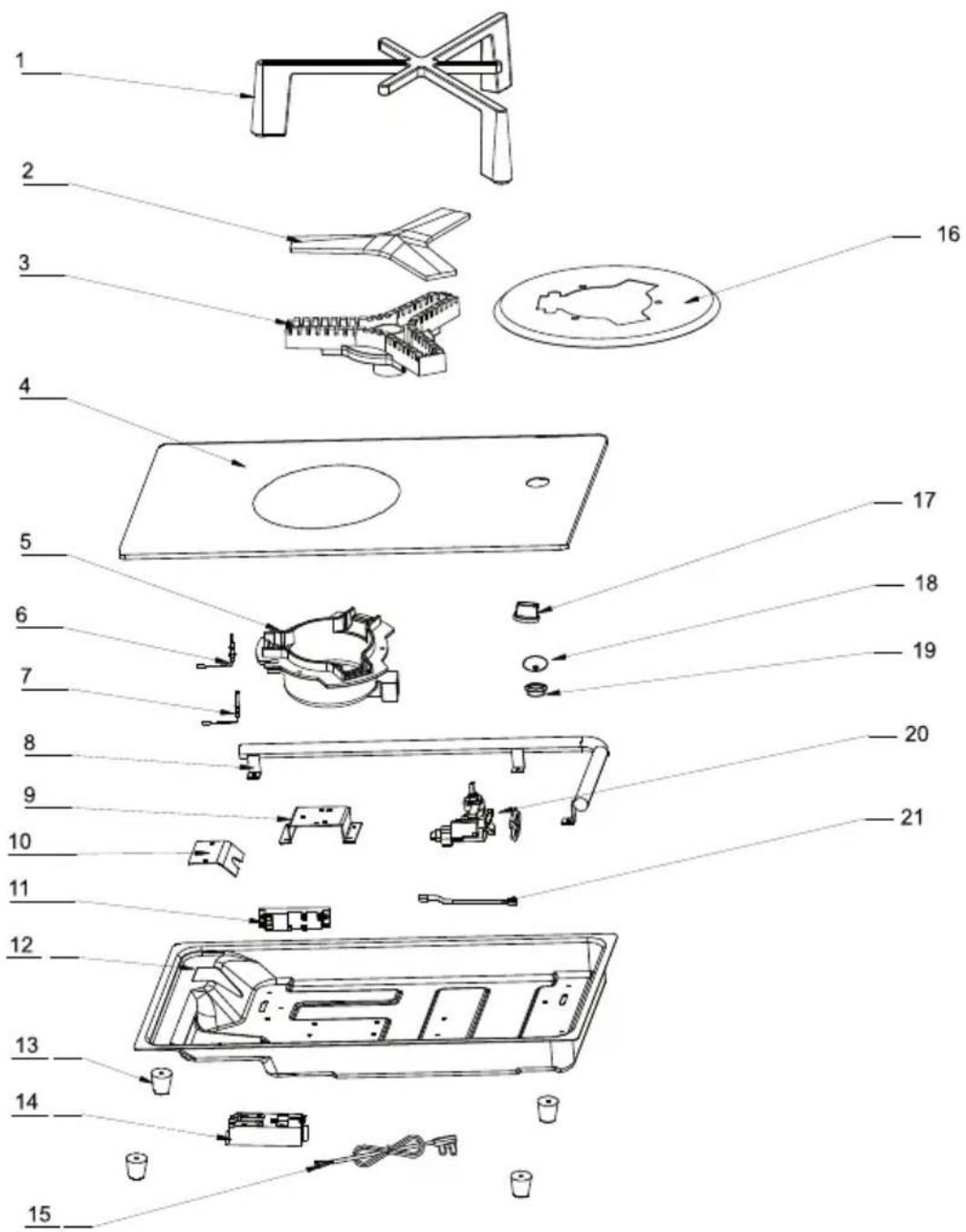
Item number 10039420
text_image
Exploded view diagram of a kitchen appliance with numbered parts for identification1 Pan support
2 Burner cap
3 Dispatcher
4 Glass
5 Burner
6 Thermocouple
7 Ignition needle
8 Gas pipe
9 Burner support
10 Protector board
11 Igniter
12 Body
13 Rubber legs
14 Wire box
15 Wire
16 Water tray
17 Knob
18 Waterproof cap for knob
19 Rubber ring for knob
20 Valve
21 Aluminum pipe
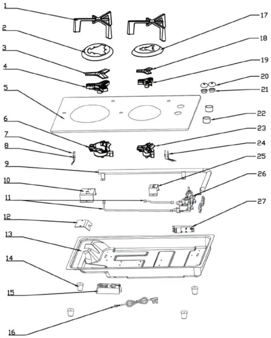
Item number 10035468
text_image
Exploded view diagram of a refrigerator with numbered parts for identification1 Pan support
2 Water tray
3 Burner cap
4 Dispatcher
5 Glass
6 Burner
7 Thermocouple
8 Ignition needle
9 Gas pipe
10 Burner support
11 Aluminium pipe
12 Protector board
13 Body
14 Rubber legs
15 Wire box
16 Wire
17 Water tray
18 Burner cap
19 Dispatcher
20 Waterproof cap for knob
21 Rubber ring for knob
22 Knob
23 Burner
24 Thermocouple
25 Burner support
26 Valve
27 Igniter
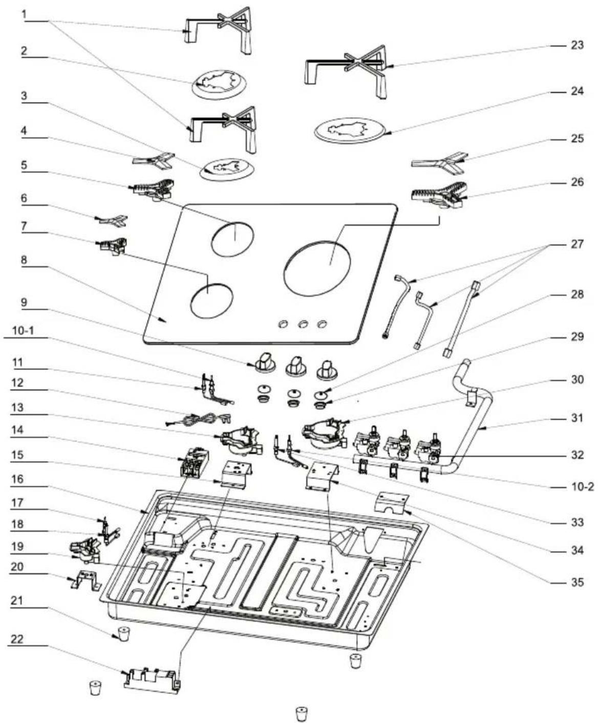
Item number 10039421
text_image
Exploded view diagram of a home appliance with numbered parts for identification1 Pan support
2 Water tray
3 Water tray
4 Burner cap
5 Dispatcher
6 Burner cap
7 Dispatcher
8 Glass
9 Knob
10 Thermocouple
11 Ignition needle
12 Wire
13 Burner
14 Wire box
15 Burner support
16 Body
17 Thermocouple
18 Ignition needle
19 Burner
20 Burner support
21 Rubber legs
22 Igniter
23 Pan support
24 Water tray
25 Burner cap
26 Dispatcher
27 Aluminium pipe
28 Waterproof cap for knob
29 Rubber ring for knob
30 Burner cap
31 Gas pipe
32 Valve
33 Ignilion needle
34 Burner support
35 Protector board
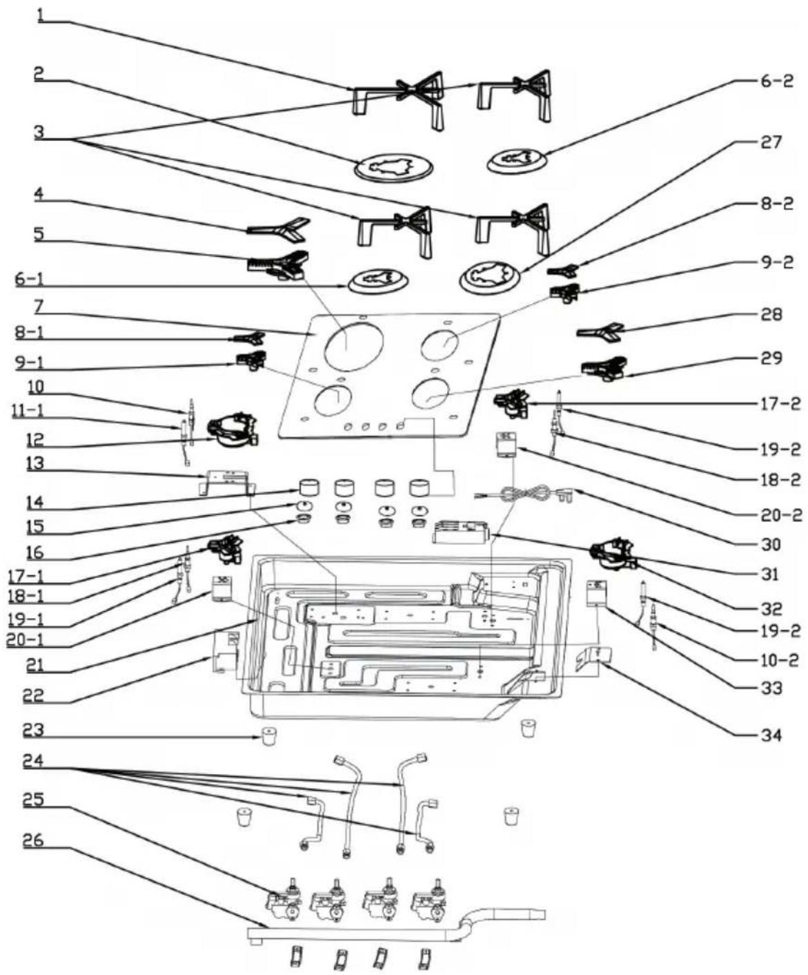
Item number 10035469
text_image
Exploded view diagram of a device with numbered parts and internal components labeled in Chinese.1 Pan support
2 Water tray
3 Pan support
4 Burner cap
5 Dispatcher
6 Burner support
7 Glass
8 Burner cap
9 Dispatcher
10 Thermocouple
11 Ignition needle
12 Burner
13 Burner support
14 Knob
15 Waterproof cap for knob
16 Rubber ring for knob
17 Burner
18 Thermocouple
19 Ignition needle
20 Burner support
21 Body
22 Igniter
23 Rubber legs
24 Gas pipe
25 Valve
26 Gas pipe
27 Water tray
28 Burner cap
29 Dispatcher
30 Wire
31 Wire box
32 Burner
33 Burner support
34 Protector board
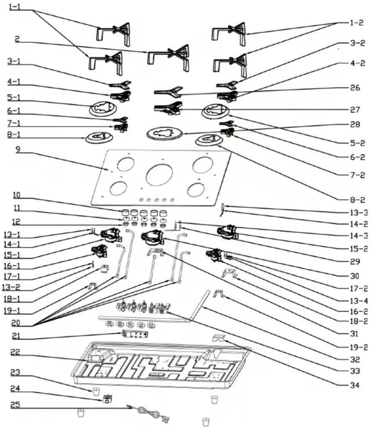
text_image
Exploded view diagram of a refrigerator with numbered parts and component labels1 Pan support
2 Pan support
3 Burner cap
4 Dispatcher
5 Water tray
6 Burner cap
7 Dispatcher
8 Water tray
9 Glass
10 Knob
11 Waterproof cap for knob
12 Rubber ring for knob
13 Ignition needle
14 Thermocouple
15 Burner
16 Burner
17 Thermocouple
18 Burner support
19 Burner support
20 Aluminium pipe
21 Igniter
22 Body
23 Rubber legs
24 Wire box
25 Wire
26 Burner cap
27 Dispatcher
28 Water tray
29 Ignition needle
30 Burner
31 Burner support
32 Gas pipe
33 Valve
34 Protector board
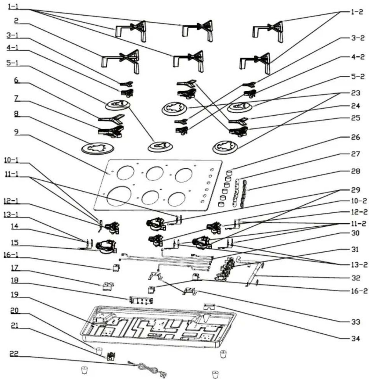
text_image
Exploded view diagram of a mechanical assembly with numbered parts and component labels1 Pan support
2 Pan support
3 Burner cap
4 Dispatcher
5 Water tray
6 Burner cap
7 Dispatcher
8 Water tray
9 Glass
10 Thermocouple
11 Ignition needle
12 Burner
13 Thermocouple
14 Ignition needle
15 Burner
16 Burner support
17 Burner support
18 Igniter
19 Body
20 Rubber legs
21 Wire box
22 Wire
23 Water tray
24 Burner cap
25 Dispatcher
26 Knob
27 Waterproof cap for knob
28 Rubber ring for knob
29 Burner
30 Aluminium pipe
31 Valve
32 Gas pipe
33 Burner support
34 Protector board
INSTALLATION
- Have the installation carried out by a qualified specialist. Have the installer show you the location of the gas shut off valve and how to shut it off in an emergency.
- Be certain all packing material are removed from the cooktop before operating, to prevent fire or smoke damage that could be caused by the presence of these materials.
- Observe all instructions for minimum clearances to any combustible surfaces. These should be in accordance with information on the rating plate and with national fire laws.
- If cooktop is installed near window, proper precaution should be taken to prevent curtains from blowing over burners creating a fire hazard.
- When choosing a location of the cooktop, consider availability and position of gas and electric supply paths.
- Any openings around gas and electric service outlets shall be closed at the time of installation.
- Do not install another cooktop next to this unit.
- The underside of the countertop must be checked to ensure that there are no projections which might foul the weight of the cooktop. Make sure that the countertop is solidly supported and can withstand the weight of the cooktop.
- Check that the cabinet is levelled from side and from front to back in its installed position.
- Cabinet ventilation can be improved by the provision of both an inlet at floor level and an outlet at higher level. Care should be taken to ensure that ventilation is not obstructed by bulky things etc.
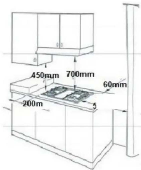
text_image
450mm 700mm 60mm 200m 5Installation below cabinet
Under any circumstances, make sure the electric hob is well ventilated and the air inlet and outlet are not blocked. Ensure the electric hob is in good work state. As shown below:
Note: The safety distance between the hotplate and the hood above the hotplate should be at least 760 mm.
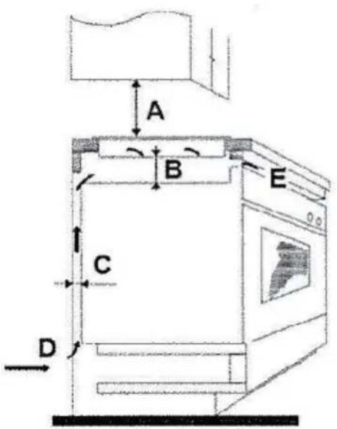
text_image
A B E C D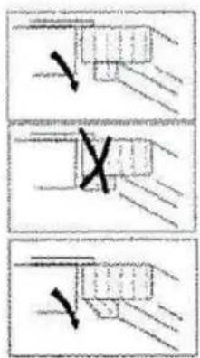
text_image
Diagram showing three steps of a mechanical or electrical process with arrows indicating direction and cross marks, likely illustrating a procedure or control.| A B C D E | ||||
| 700 mm min | 100 mm min 20 | mm Air intake Air | exit 5 mm |
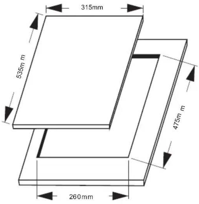
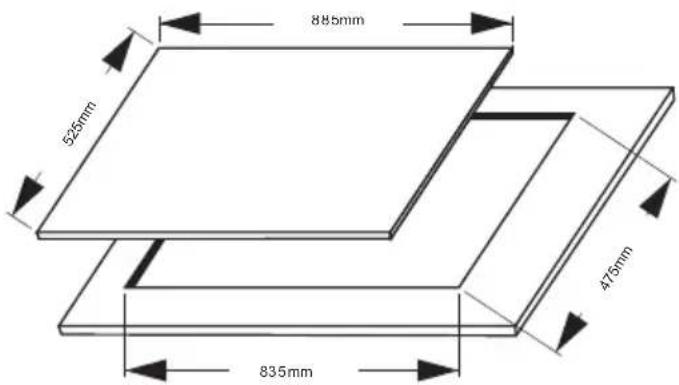
Opening dimension
10039420 & 10035468
text_image
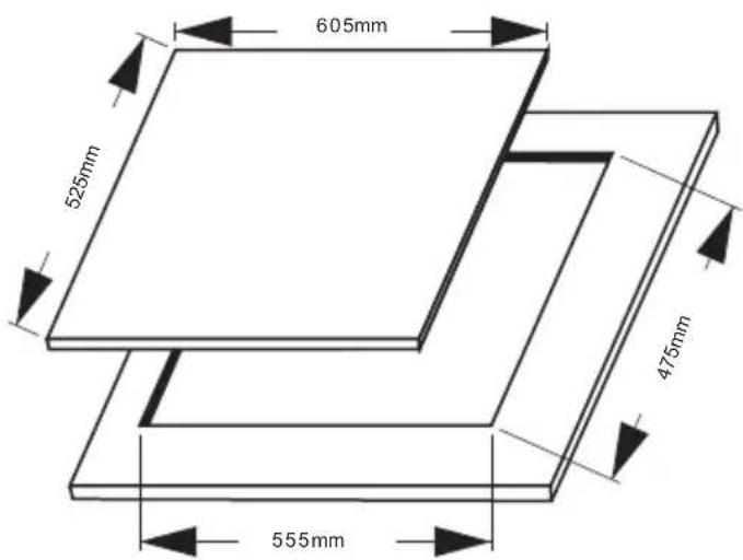
315mm 535m m 475m m 260mm10039421 & 10035469

text_image
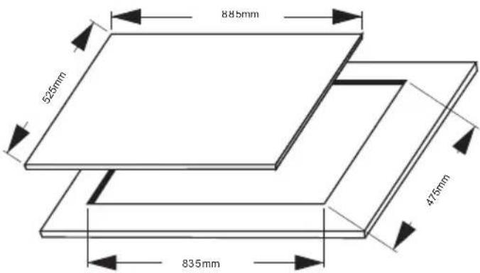
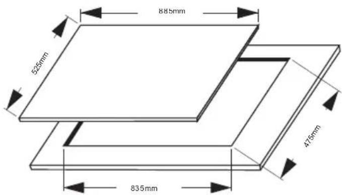
605mm 525mm 475mm 555mm10039422 & 10035470
text_image
885mm 525mm 475mm 835mmAssembly of the fixing bracket Part A
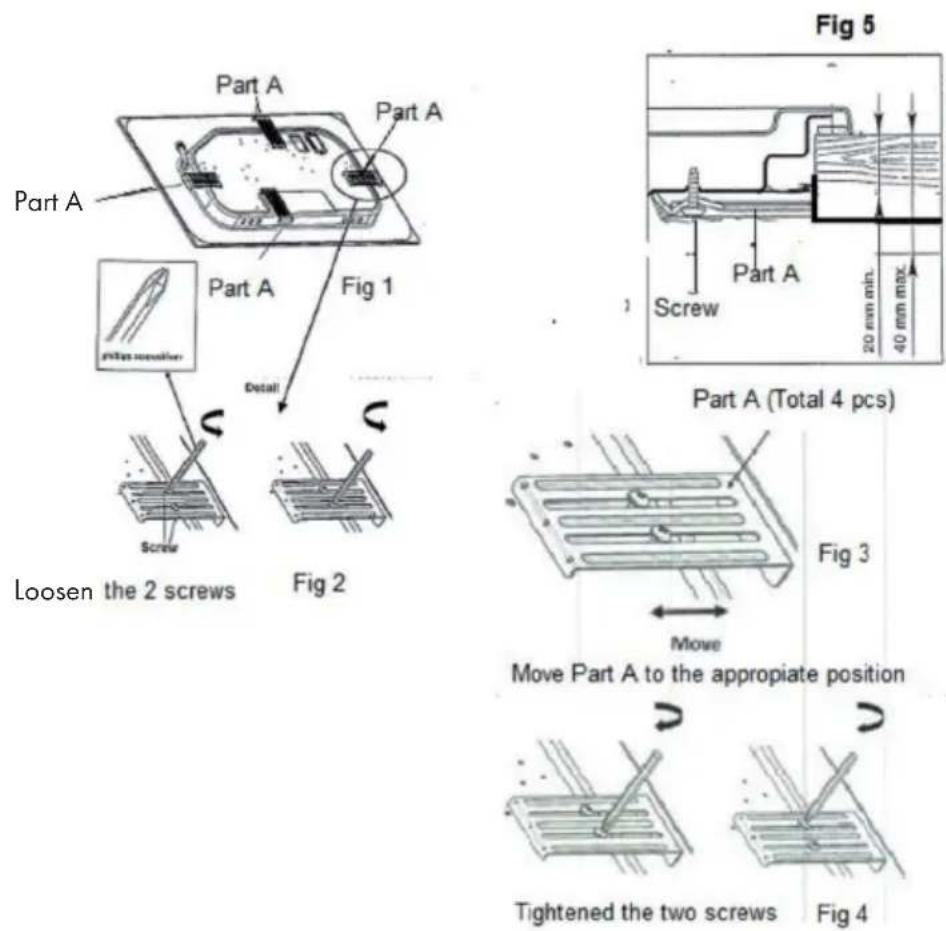
The cooking hob is supplied with a set of 4 pcs fixing bracket Part A (Fig 1) and two screws each for fixing into the kitchen cabinet with a worktop from 2 to 4 cm deep (Fig 5). Slot in the cooking hob into the aperture of the cabinet and set it correctly. Move Part A to the appropriate position (Fig 3). Loosen the screws and adjust the bracket Part A (Fig 2) until the cooking hob is firmly secured and then tighten the screw (Fig 4).
Installation safety
- Prior to installation, ensure that the local distribution conditions (nature of the gas and gas pressure) and the adjustment of the appliance are compatible.
- The adjustment conditions for this appliance are stated on the label (or data plate).
- This appliance is not connected to a combustion products evacuation device. It shall be installed and connected in accordance with current installation regulations. Particular attention shall be given to the relevant requirements regarding ventilation.
- The use of a gas cooking appliance results in the production of heat, moisture and products of combustion in the room in which it is installed. Ensure that the kitchen is well ventilated especially when the appliance is in use: Keep natural ventilation holes open or install a mechanical ventilation device (mechanical extractor hood).
- Prolonged intensive use of the appliance may call for additional ventilation, for example opening of a window, or more effective ventilation, for example increasing the level of mechanical ventilation where present.
- This appliance is for cooking purposes only. It must not be used for other purposes, for example room heating.

text_image
Warning symbol with exclamation mark inside a triangleCAUTION
In case of hotplate glass breakage
Shut immediately off all burners and any electrical heating element and isolate the appliance from the power supply.
Do not touch the appliance surface.
Do not use the appliance.
DISASSEMBLY
Note: Installation/assembly and disassembly of the unit must only be carried out by qualified personnel.
Before dismantling, any gas in the unit must be vented. Proceed as follows:
- Close all supply valves, but do not disconnect the gas cooker from the line yet.
- Now light all the burners. The remaining gas contained in the appliance burns off in a short time.
- After that, the appliance's pipes are free of gas and the gas cooker can be disconnected from the connections.
Important notes on dismantling the unit
- The disassembly is the same as the installation/assembly in the reverse order of the steps.
- Have a second person help you during disassembly to avoid injury.
- Ensure sufficient ventilation of the working area during disassembly.
- There are no motors or accumulators in this gas hob. Observe the section "Disposal Considerations".
DISPOSAL CONSIDERATIONS
natural_image
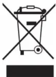
Symbol of a trash bin crossed out by a diagonal line, with no text or labels present.If there is a legal regulation for the disposal of electrical and electronic devices in your country, this symbol on the product or on the packaging indicates that this product must not be disposed of with household waste. Instead, it must be taken to a collection point for the recycling of electrical and electronic equipment. By disposing of it in accordance with the rules, you are protecting the environment and the health of your fellow human beings from negative consequences. For information about the recycling and disposal of this product, please contact your local authority or your household waste disposal service.
MANUFACTURER & IMPORTER (UK)
Manufacturer:
Chal-Tec GmbH, Wallstrasse 16, 10179 Berlin, Germany.
Importer for Great Britain:
Berlin Brands Group UK Ltd
PO Box 1145
Oxford, OX1 9UW
United Kingdom
EU PRODUCT DATA SHEET
This document serves to demonstrate conformity with Regulation (EU) No 66/2014.
Specifications according to EN 30-2-1:2015
The energy efficiency of gas burners in a domestic hob is calculated as follows:
$$ E E _ {g a s b u r n e r} = \frac {E _ {t h e o r e t i c}}{E _ {g a s b u r n e r}} \times 1 0 0 $$
| Symbol Burner Value Unit | ||||
| Model identification | 10039420 | |||
| Type of hob | Gas Hob | |||
| Number of gas burner | - - - - 1 - - | |||
| Energy efficiency per gas burner | EE_gas burner | Wok burner 60.0 % | ||
| Rapid burner - - % | ||||
| Semi-rapid burner - - % | ||||
| Auxiliary burner - - % | ||||
| Energy efficiency per gas hob | EE_gas hob | 60.0 % | ||
| Symbol Burner Value Unit | ||||
| Model identification | 10035468 | |||
| Type of hob | Gas Hob | |||
| Number of gas burner | - - - - 2 - - | |||
| Energy efficiency per gas burner | EE_gas burner | Wok burner | - - % | |
| Rapid burner - - % | ||||
| Semi-rapid burner | 56.4 % | |||
| Auxiliary burner | N/A % | |||
| Energy efficiency per gas hob | EE_gas hob | 56.4 % | ||
| Model identification | 10039421 | |||
| Type of hob | Gas Hob | |||
| Number of gas burner | - - - - 3 - - | |||
| Energy efficiency per gas burner | EE_gas burner | Wok burner 58.0 % | ||
| Rapid burner - - % | ||||
| Semi-rapid burner 58.0 % | ||||
| Auxiliary burner - - % | ||||
| Energy efficiency per gas hob | EE_gas hob | 58.0 % | ||
| Symbol Burner Value Unit | ||||
| Model identification | 10035469 | |||
| Type of hob | Gas Hob | |||
| Number of gas burner | - - - - 4 - - | |||
| Energy efficiency per gas burner | EE_gas burner | Wok burner - - % | ||
| Rapid burner | 56.1 % | |||
| Semi-rapid burner | 56.4 % | |||
| Auxiliary burner | N/A % | |||
| Energy efficiency per gas hob | EE_gas hob | 56.3 % | ||
| Symbol Burner Value Unit | ||||
| Model identification | 10035470 | |||
| Type of hob | Gas Hob | |||
| Number of gas burner | - - - - 5 - - | |||
| Energy efficiency per gas burner | EE_gas burner | Wok burner - - % | ||
| Rapid burner | 57.5 | % | ||
| Semi-rapid burner | 57.3 | % | ||
| Auxiliary burner | N/A % | |||
| Energy efficiency per gas hob | EE_gas hob | 57.4 | % | |
| Symbol | Burner Value Unit | |||
| Model identification | 10039422 | |||
| Type of hob | Gas Hob | |||
| Number of gas burner | - - - - 6 - - | |||
| Energy efficiency per gas burner | EE_gas burner | Wok burner 58.0 % | ||
| Rapid burner - - % | ||||
| Semi-rapid burner 58.0 % | ||||
| Auxiliary burner - - % | ||||
| Energy efficiency per gas hob | EE_gas hob | 58.0 % | ||
Cher client, chère cliente,
text_image
QR code image containing encoded data, no visible human-readable textSOMMAIRE
text_image
Warning symbol with exclamation mark inside a trianglenatural_image
Line drawing of a hand holding a ball bearing, with no text or symbols presenttext_image
Warning sign with exclamation mark inside a triangleMISE EN GARDE
text_image
Exploded view diagram of a refrigerator with numbered parts for identificationtext_image
Exploded view diagram of a refrigerator with numbered parts for identificationtext_image
Exploded view diagram of a device with numbered parts, likely for assembly or manufacturing purposes.text_image
Exploded view diagram of a device with numbered parts and internal components labeled in Chinese.text_image
Exploded view diagram of a device with numbered parts and component layoutstext_image
Exploded view diagram of a device with numbered parts and component layouts, including zoomed-in views and labeled parts.1 Porte-casserole
2 Porte-casserole
text_image
450mm 700mm 60mm 200m 500mmtext_image
Diagram showing three steps of a mechanical or electrical process with arrows indicating direction and cross marks, likely illustrating a procedure or control.text_image
315mm 535m m 475m m 260mm10039421 & 10035469
text_image
605mm 525mm 475mm 555mm10039422 & 10035470
text_image
885mm 525mm 475mm 835mmFixer le support (partie A)
text_image
Warning sign with exclamation mark inside a triangleATTENTION
natural_image
Symbol of a trash bin crossed with a diagonal line, no text or numbers presentBerlin Brands Group UK Ltd
PO Box 1145
Oxford, OX1 9UW
United Kingdom
FICHE DE DONNÉES PRODUIT UE
text_image
QR code image containing encoded data, no visible human-readable textÍNDICE
text_image
Warning symbol with exclamation mark inside a triangleADVERTENCIA
natural_image
Line drawing of a hand holding a ball bearing, with no text or symbols presenttext_image
Warning sign with exclamation mark inside a triangleADVERTENCIA
text_image
Exploded view diagram of a refrigerator with numbered parts for identificationtext_image
Exploded view diagram of a refrigerator with numbered parts for identificationtext_image
Exploded view diagram of a kitchen appliance with numbered parts for identificationtext_image
Exploded view diagram of a device with numbered parts and internal components labeled in Chinese.text_image
Exploded view diagram of a device with numbered parts and component layoutstext_image
Exploded view diagram of a device with numbered parts and component layouts, including zoomed-in views and labeled parts.text_image
450mm 700mm 60mm 200mm 500mmtext_image
Diagram showing three steps of a mechanical or electrical process with arrows indicating direction and cross marks, likely illustrating a procedure or control.text_image
315mm 535m m 475m m 260mm10039421 y 10035469
text_image
605mm 525mm 475mm 555mm10039422 y 10035470
text_image
885mm 525mm 475mm 835mmtext_image
Warning symbol with exclamation mark inside a triangleATENCIÓN
natural_image
Symbol of a trash bin crossed with a diagonal line, no text or numbers presentBerlin Brands Group UK Ltd
PO Box 1145
Oxford, OX1 9UW
United Kingdom
FICHA TÉCNICA DEL PRODUCTO UE
$$ E E _ {\text { gas burner }} = \frac {E _ {\text { theoretic }}}{E _ {\text { gas burner }}} \times 1 0 0 $$
text_image
QR code image containing encoded data, no visible human-readable textINDICE
text_image
Warning symbol with exclamation mark inside a triangleAVVERTENZA
natural_image
Line drawing of a hand holding a ball bearing with a pointer (no text or symbols)text_image
Warning sign with exclamation mark inside a triangleAVVERTIMENTO
text_image
Exploded view diagram of a refrigerator with numbered parts for identificationtext_image
Exploded view diagram of a refrigerator with numbered parts for identificationtext_image
Exploded view diagram of a kitchen appliance with numbered parts for identificationtext_image
Exploded view diagram of a device with numbered parts for identification and assembly reference.text_image
Exploded view diagram of a mechanical assembly with numbered parts and component labelstext_image
Exploded view diagram of a mechanical assembly with numbered parts and component labelstext_image
450mm 700mm 200m 60mm 500mmtext_image
Diagram showing three steps of a mechanical or electrical process with arrows indicating direction and cross marks, likely illustrating a procedure or control.text_image
315mm 535m m 475m m 260mm10039421 & 10035469
text_image
605mm 525mm 475mm 555mm10039422 & 10035470
text_image
885mm 525mm 475mm 835mmFissare la staffa (parte A)
text_image
Warning sign with exclamation mark inside a triangleATTENZIONE
natural_image
Symbol of a trash bin crossed out by a diagonal line, with no text or labels present.PRODUTTORE E IMPORTATORE (UK)
Produttore:
Chal-Tec GmbH, Wallstraße 16, 10179 Berlino, Germania.
Berlin Brands Group UK Ltd
PO Box 1145
Oxford, OX1 9UW
United Kingdom
