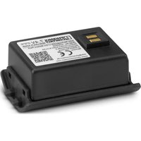
CF CRIMPHANDY - Power tool Phoenix Contact - Free user manual and instructions
Find the device manual for free CF CRIMPHANDY Phoenix Contact in PDF.


| Product type | Mobile crimping tool |
| Brand | Phoenix Contact |
| Model | CF CRIMPHANDY 0.5 / 0.75 / 1.0 / 1.5 |
| Dimensions (W x H x D) | 43 mm x 205 mm x 70 mm |
| Weight | 450 g |
| Power supply | Lithium-ion battery 7.4 V DC, 5.92 Wh, 800 mAh; mains charger 100–240 V AC, 50–60 Hz |
| Battery life | Up to 3,000 crimping cycles per charge |
| Charging time | Approximately 65 min; usable after 20 min |
| Suitable conductor cross-sections | 0.5 / 0.75 / 1.0 / 1.5 mm² (depending on model) |
| Conductor types | H05V-K, H07V-K (class 5 IEC 60228, PVC insulation) |
| Compatible ferrules | Ferrule strips AI...-8...-S (socket length 8 mm, 50 units) |
| Crimping type | Four-point (square shape) |
| Working cycle | < 2 s |
| Operating temperature | +15 °C to +30 °C (tool); +5 °C to +40 °C (charger) |
| Auto shut-off | After 5 minutes of inactivity |
| Indicators | 3 LEDs (green, yellow, red) for status and errors |
| Safety | Inductive cross-section sensor, visual 'Wire Check', stop on detection of inappropriate cross-section |
| Delivery contents | Case, crimping tool, cable cutter CUTFOX 12, ferrule strip, service tool, waste deflector (GP2), brief instructions |
| Recommended accessories | Charger CF CRIMPHANDY/CHARGER (1212519), battery CF CRIMPHANDY/ACCU (1212518), cutting module CF CRIMPHANDY CUTTER (1212520) |
| Maintenance | Check crimp quality every 5,000 cycles or 1 year; replace waste deflectors if bent; contact Phoenix Contact for repair |
| Repairability | Do not open or repair yourself; return to manufacturer for any defect |
| Warranty and compliance | Machinery Directive 2006/42/EC, EMC, RoHS; standards EN 60335, EN 55014, EN 62061 |
Frequently Asked Questions - CF CRIMPHANDY Phoenix Contact
User questions about CF CRIMPHANDY Phoenix Contact
0 question about this device. Answer the ones you know or ask your own.
Ask a new question about this device
Download the instructions for your Power tool in PDF format for free! Find your manual CF CRIMPHANDY - Phoenix Contact and take your electronic device back in hand. On this page are published all the documents necessary for the use of your device. CF CRIMPHANDY by Phoenix Contact.
USER MANUAL CF CRIMPHANDY Phoenix Contact
natural_image
Close-up of a hand holding a Phoenix Contag tool with a screwdriver nearby (no visible text or symbols on the tool itself)CF CRIMPHANDY
UM IA CF CRIMPHANDY - 2910936
EN Original operating instructions
FR Instructions de service originales
Koffer mit:
natural_image
Mechanical assembly diagram showing two views of a tool handle with directional arrows indicating movement (no text or symbols)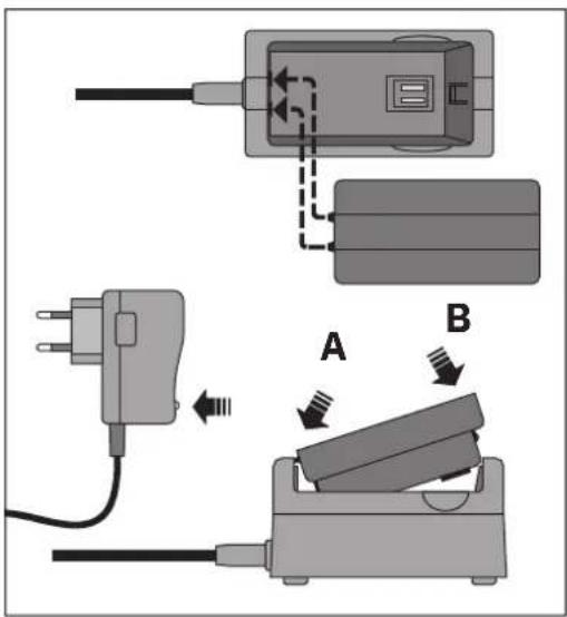
Akkufach entriegeln
natural_image
Hand holding a mechanical device with a green indicator light on its side (no text or symbols visible)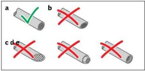
Leiter abschneiden
natural_image
Close-up of a mechanical component with a central circular button and three colored indicators (green, red, black) on its surface (no text or symbols visible)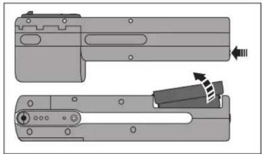
natural_image
Technical illustration of a mechanical component with two views showing internal features and directional arrows (no text or symbols)natural_image
Diagram of a mechanical component with a screw and connector, showing a close-up inset of three circular ports (no text or symbols present)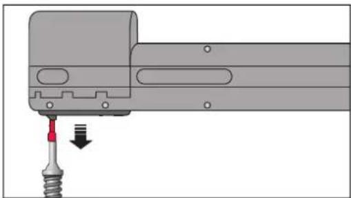
natural_image
Mechanical assembly diagram showing a tool inserted into a component with a red arrow indicating direction (no text or symbols present)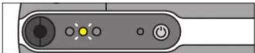
natural_image
Close-up of a device control panel with buttons and indicator lights (no text or symbols visible)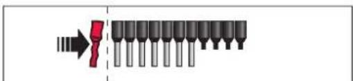

natural_image
Mechanical assembly diagram showing a gear-like component being inserted into a shaft (no text or symbols visible)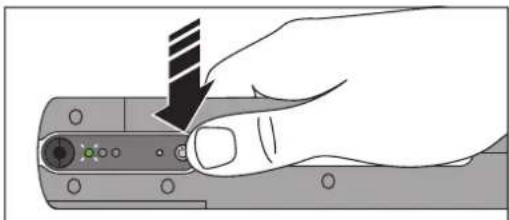
natural_image
Hand holding a computer monitor with a striped cable inserted, no visible text or symbolsnatural_image
Illustration of a hand holding a mechanical device with arrows indicating motion or force (no text or symbols)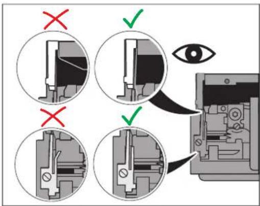
natural_image
Hand holding a computer mouse with a striped tip, pointing to the screen (no text or symbols visible)
natural_image
Diagram showing a red arrow pointing to a row of black cylindrical objects, with no visible text or symbols.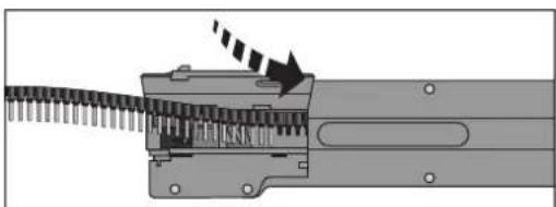
natural_image
Mechanical assembly diagram showing a gear-like component with a rotating shaft and directional arrow (no text or symbols)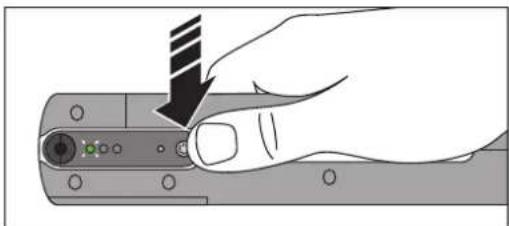
natural_image
Hand holding a mechanical component with a striped tool, no visible text or symbolsnatural_image
Illustration of a hand using a power tool to adjust or install a component, with no visible text or symbols.natural_image
Mechanical assembly diagram showing internal components and a magnified view of a mechanical assembly (no text or symbols)natural_image
Diagram showing a hand inserting a screwdriver into an internal mechanical component (no text or symbols visible)natural_image
Mechanical assembly diagram showing a close-up of a component with an arrow indicating rotation (no text or symbols present)natural_image
Illustration of a hand holding a device with arrows indicating movement or force (no text or symbols present)natural_image
Mechanical assembly diagram showing a component being cut into a housing (no text or symbols visible)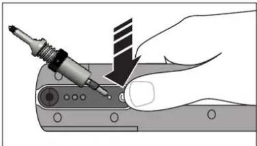
natural_image
Illustration of a hand using a power tool to adjust or install a component, with no visible text or symbols.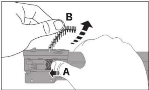
natural_image
Mechanical assembly diagram showing a valve mechanism with rotating components (no text or labels)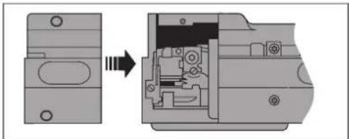
natural_image
Mechanical assembly diagram showing a component being cut into a housing (no text or symbols present)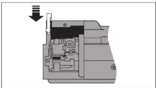
natural_image
Cross-sectional diagram of a mechanical device showing internal components and a downward arrow (no text or symbols)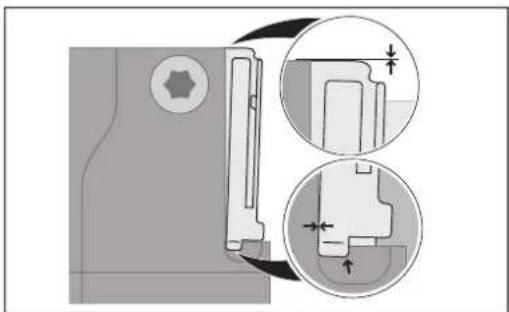
natural_image
Technical diagram showing mechanical assembly with cross-sectional views and dimension arrows (no text or labels)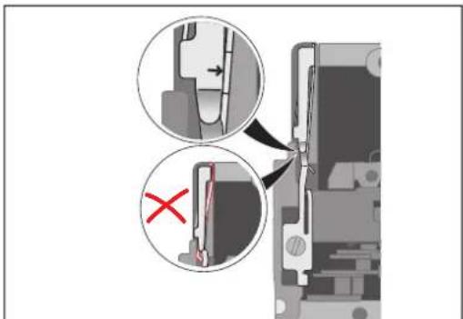
natural_image
Diagram showing a mechanical assembly with an open component and a close-up view of internal components (no text or symbols)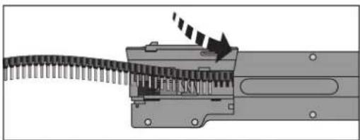
natural_image
Mechanical assembly diagram showing a gear-like component being inserted into a housing with a directional arrow indicating motion (no text or symbols present)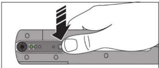
natural_image
Hand holding a device with a black arrow pointing to a button (no text or symbols visible)(OJ No. L157, 9 June 2006)
2011/65/EU
(OJ L 174, 1 July 2011)
2014/30/EU
(OJ L 96, 29 March 2014)
Original operating instructions
Operation of the portable CF CRIMPHANDY crimping tool
UM EN CF CRIMPHANDY, Revision 08
2025-03-10
This manual is valid for:
Designation Item No.
CF CRIMPHANDY 0,5 1212463
CF CRIMPHANDY 0,75 1212464
CF CRIMPHANDY 1,0 1212465
CF CRIMPHANDY 1,5 1212466
CF CRIMPHANDY/ACCU 1212518
CF CRIMPHANDY/CHARGER 1212519
Table of contents
1 For your safety ....5
1.1 Identification of warning notes....5
1.2 Qualification of users ....5
1.3 Field of application of the product....6
1.4 Correct use of the battery and charger....7
1.5 Disposal....8
2 Description of the crimping tool 9
2.1 Scope of supply 9
2.2 Overview of the operating elements....9
3 Operating the crimping tool 10
3.1 Suitable conductors and ferrules.... 10
3.2 Charging the battery.... 12
3.3 Switching on the crimping tool 13
3.4 Inserting the ferrule tape 14
3.5 Crimping....15
3.6 Loading the ferrule tape.... 16
3.7 Removing the battery....16
4 Troubleshooting 17
4.1 Overview of possible faults.... 17
4.2 Meaning of the indicator lights.... 19
4.3 Troubleshooting sequences.... 20
4.4 Removing the conductor 21
4.5 Removing the ferrule.... 22
4.6 Removing a blockage at the ferrule transport.... 23
4.7 Removing loose parts.... 25
4.8 Initializing the crimping tool (reset).... 27
4.9 Replacing the waste guide plates 28
4.10 Returning a product.... 34
A Appendix 35
A 1 Technical data....35
A 2 Ordering data....36
A 3 EU declaration of conformity .... 38
1 For your safety
Read this manual carefully and keep it for future reference.
1.1 Identification of warning notes

This symbol indicates hazards that could lead to personal injury.
There are three signal words indicating the severity of a potential injury.
DANGER
Indicates a hazard with a high risk level. If this hazardous situation is not avoided, it will result in death or serious injury.
WARNING
Indicates a hazard with a medium risk level. If this hazardous situation is not avoided, it could result in death or serious injury.
CAUTION
Indicates a hazard with a low risk level. If this hazardous situation is not avoided, it could result in minor or moderate injury.

This symbol together with the NOTE signal word warns the reader of actions that might cause property damage or a malfunction.

Here you will find additional information or detailed sources of information.
1.2 Qualification of users
This manual is addressed to persons who are familiar with the relevant safety concepts for handling electrical machines.
The user must read this manual or be instructed by a skilled person. The user needs knowledge of how to handle the device and what to look out for. Otherwise, this may result in malfunctions.
1.3 Field of application of the product
The portable crimping tool strips conductors in one step and crimps on a ferrule. It crimps ferrules in square form.
NOTE: To ensure error-free use and the process reliability of the portable crimping tool, only use the conductors and ferrules described.
Using unsuitable materials may damage the crimping tool and lead to inferior work results.
We recommend that you check the quality of the crimp connections every 5000 cycles or at the latest after a year.
The crimping tool is equipped with an inductive sensor that checks the actual conductor cross-section. If the cross-section exceeds or falls below the defined limits, the crimping tool does not trigger. The LEDs signal when a cross-section is detected as being unsuitable.
In exceptional cases, the crimping tool can process conductors even though they are not suitable. This leads to crimping results that do not conform with the standards.
Incorrect operation or modifications to the device can endanger your safety or damage the device. Do not repair the device yourself. If the device is defective, please contact Phoenix Contact.
1.4 Correct use of the battery and charger
The portable crimping tool works with a lithium-ion battery that is sufficient for at least 3000 crimping operations. The wide-range power supply unit can be used worldwide with a mains plug adapter.

WARNING: Important safety notes for lithium-ion batteries Risk of short circuit, fire, explosion, electric shock, or damage to health
- Do not charge the battery if it is damaged.
- Only charge the battery with the following charger: CF CRIMPHANDY/CHARGER, 1212519
- Keep the battery away from metal objects. Paper clips, coins, keys, nails, and other metal objects that touch the contacts may cause a short circuit.
- Never expose the battery to fire, water, or moisture. There is a risk of explosion.
- Do not expose the battery to direct sunlight.
- Do not place the battery on heat sources (e.g., heaters).
- Never touch the contact surfaces of the charger.
- Do not open the battery housing. Do not break apart the cells.
Note the following when charging the battery
- Do not charge the battery in a closed container. Ventilation must be ensured during charging.
- To ensure a long service life for the lithium-ion battery, store it without charging it.
- Charge the battery at ambient temperatures from +5°C ... +40°C, ideally at +15°C ... +25°C.
- During charging, the indicator light on the charger lights up red. When the battery is fully charged, the indicator light lights up green.
- Remove the battery from the charger once it has been fully charged. Disconnect the charger from the mains.
- The charging duration is 65 minutes, the battery can be used after 20 minutes.
- Only use the charger with the following battery: CF CRIMPHANDY/ACCU, 1212518. Failure to observe this requirement may result in the battery exploding.
1.5 Disposal

The symbol with the crossed-out trash can indicate that this item must be collected and disposed of separately from other waste. Phoenix Contact or public collection sites will take the item back for free disposal. For information on the available disposal options, visit phoenixcontact.com. Collect and dispose of included batteries separately from other waste.

Dispose of batteries separately from other waste via specialized companies or appropriate collection sites in accordance with national laws.
2 Description of the crimping tool
2.1 Scope of supply
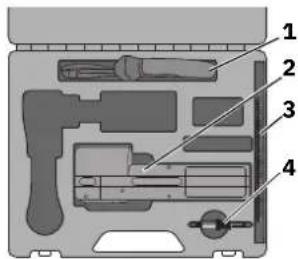
Case contents:
1 Cable cutter
2 Crimping tool
3 Ferrule tape
4 Service tool
– Laminated brief instructions
– Waste guide plate (GP2), see Section 4.9
- This manual
Necessary accessories
- Charger (CF CRIMPHANDY/CHARGER, 1212519)
- Battery (CF CRIMPHANDY/ACCU, 1212518)
2.2 Overview of the operating elements
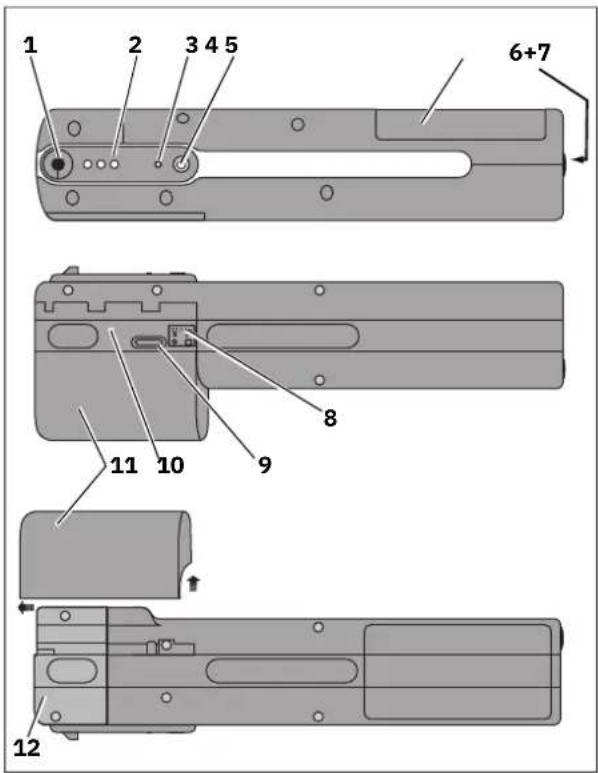
Crimping tool
1 Shaft for conductor
2 Pilot lights
3 Reset button
The reset button may only be used in the course of troubleshooting as described in Section 4.
4 ON button
5 Battery compartment
6 Release button for battery compartment
7 M5 thread for attaching the crimping tool to a balancer
8 Wire check
9 Window for ferrule magazine
10 Flap for opening the ferrule magazine
11 Waste container
12 Service cover
3 Operating the crimping tool
NOTE: Only use the crimping tool at ambient temperatures of +15°C ... +30°C.
NOTE: Do not remove the battery during the crimping process.
3.1 Suitable conductors and ferrules
Suitable conductors
The mobile crimping tool is designed to process fine-stranded class 5 conductors with PVC insulation in accordance with IEC 60228. Only use type H05V-K and H07V-K conductors. Conductors with very hard insulation such as rubber, silicone, Teflon, and textile insulation are not suitable.
Avoid processing conductors that are very cold (e.g., directly from an unheated warehouse). The colder the materials to be processed are, the harder and more resistant they become. This can lead to increased wear or to mechanical damage.
Please note that the crimping tool can only process a specific conductor cross-section. A significantly deviating conductor cross-section will be detected and not processed. It may be possible to process similar conductor cross-sections, but this could endanger the electrical connection. Make sure that the conductor cross-section and ferrules fit together.
| Device type Metric conductor cross-section | Outside diameter Conductor type | ||
| CF CRIMPHANDY 0,5 | 0.5 mm ^2 | 1.7 mm ... 2.4 mm | H05V-K |
| CF CRIMPHANDY 0,75 | 0.75 mm ^2 | 1.9 mm ... 2.6 mm | H05V-K |
| CF CRIMPHANDY 1,0 | 1.0 mm ^2 | 2.0 mm ... 2.7 mm | H05V-K |
| CF CRIMPHANDY 1,5 | 1.5 mm ^2 | 2.4 mm ... 3.1 mm | H07V-K |
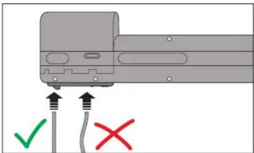
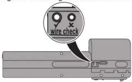
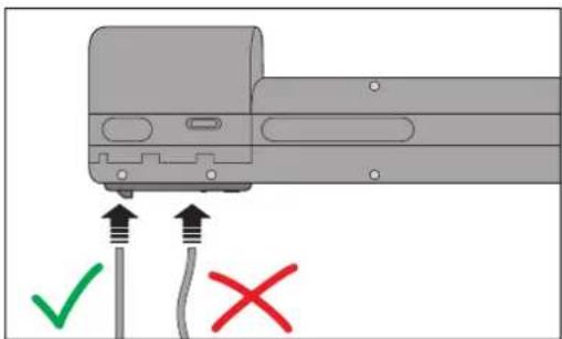
Wire check
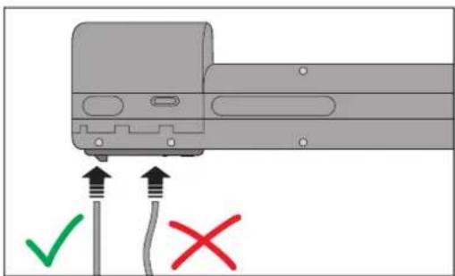
For checking the outside conductor diameter, the mobile crimping tool has two openings that are labeled "wire check". The conductor has to fit in the opening that is labeled with the checkmark. If the conductor fits in the small opening with the cross, you must not use it.
Conductors that are too thick or too thin cause the crimping tool to be damaged.
Figure 3-1 Checking the outside diameter of the conductor
Suitable ferrules
Only use ferrule tape from Phoenix Contact that has a specific function end. This special design is required for safe operation.
| Device type Ferrule tape from Phoenix Contact | ||||
| CF CRIMPHANDY 0,5 | AI 0,5-8 WH-S 1212521 | AI 0,5-8 OG-S 1212784 |  | |
| CF CRIMPHANDY 0,75 | AI 0,75-8 GY-S 1212522 | AI 0,75-8 BU-S 1212785 | ||
| AI 0,75-8 WH-S 1212783 | ||||
| CF CRIMPHANDY 1,0 | AI 1,0-8 RD-S 1212523 | AI 1,0-8 YE-S 1212782 | ||
| CF CRIMPHANDY 1,5 | AI 1,5-8 BK-S 1212524 | AI 1,5-8 RD-S 1212781 | ||
Preparing the conductor
In order to ensure optimum operation of the portable crimping tool, the conductor must be prepared correctly. Make sure that the conductors are always cut straight. Do not use crimped, diagonally cut, or already stripped conductors. Even for very short conductors it may happen that they are not crimped correctly.
Only use cable cutters with sharp blades that cut the conductors and do not squeeze them. Do not use diagonal cutters or similar unsuitable tools.
Quality of the crimping result
The quality of the crimping result depends on:
- The stranding of the conductor
- The processing temperature
– The tolerance at the cross-section

NOTE: The user has to make sure that only suitable materials are used.
3.2 Charging the battery
natural_image
Mechanical assembly diagram showing two views of a tool handle with directional arrows indicating movement (no text or symbols)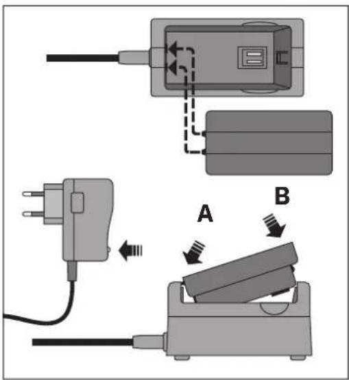
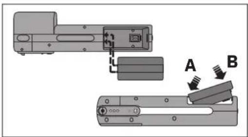
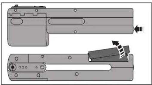
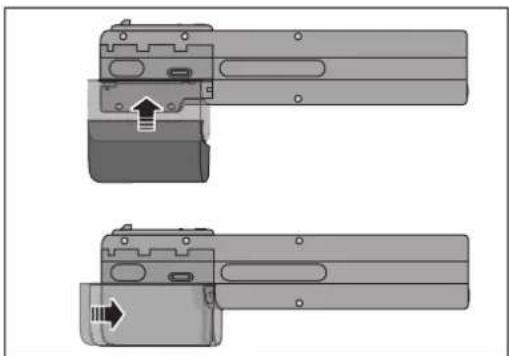
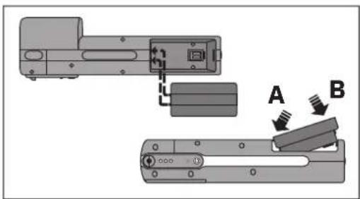
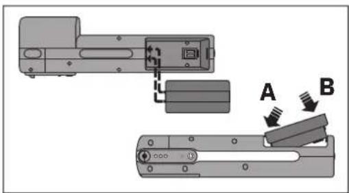
Unlocking the battery compartment
- Press the release button on the bottom of the crimping tool. The battery springs into the removal position.
- Remove the battery from the crimping tool.
The battery is already charged when delivered.
Charging the battery

NOTE: Please refer to section 1.4 "Correct use of the battery and charger".
- Place both pins of the battery in the recesses on the cable side of the charger.
- Press down on the battery at the opposite end.
- Insert the mains plug into the socket.
During charging, the indicator light on the mains plug lights up red. It changes to green when the charging process has been completed.
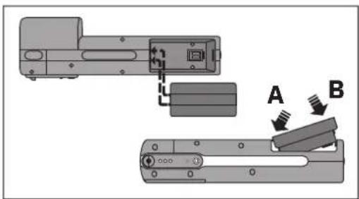
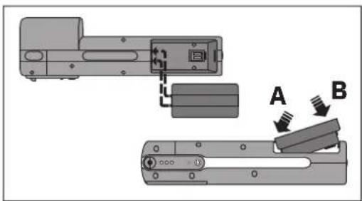
Inserting the battery in the crimping tool
- Insert the battery in the battery compartment of the crimping tool.
• Proceed in the same way as for inserting the battery in the charger.
The recesses are towards the front of the device.
The battery engages with a click.
3.3 Switching on the crimping tool
natural_image
Hand holding a handheld electronic device with a green indicator light (no text or symbols visible)Switching on the crimping tool
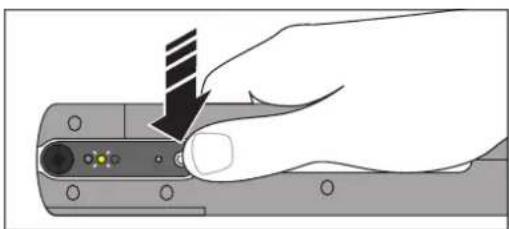
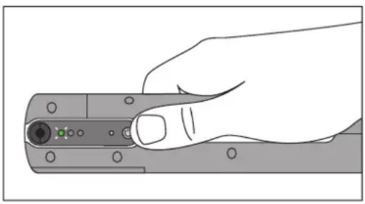
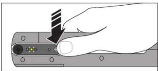
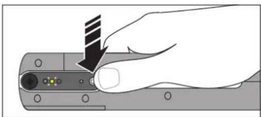
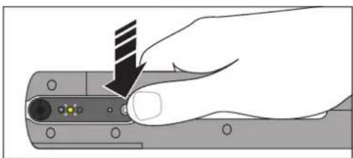
- Press the ON button briefly. The green indicator light flashes. The crimping tool is ready for use. The yellow light flashes if no ferrule tape is inserted.
-
If the ON button is held down longer when switching on, the three indicator lights indicate the charging state of the battery.
-
Green = battery full
- Yellow = battery half full
- Red = battery almost empty
Troubleshooting
- When the green and red indicator lights flash simultaneously, the battery is empty. Follow the instructions for charging the battery (see page 12).
- When the yellow indicator light flashes, follow the sequence for inserting a ferrule tape (see page 14).
Switching off the crimping tool
- Press the ON button for approx. three seconds. The three indicator lights briefly show the charging state of the battery. After approximately five minutes of no activity, the crimping tool switches itself off automatically.
3.4 Inserting the ferrule tape
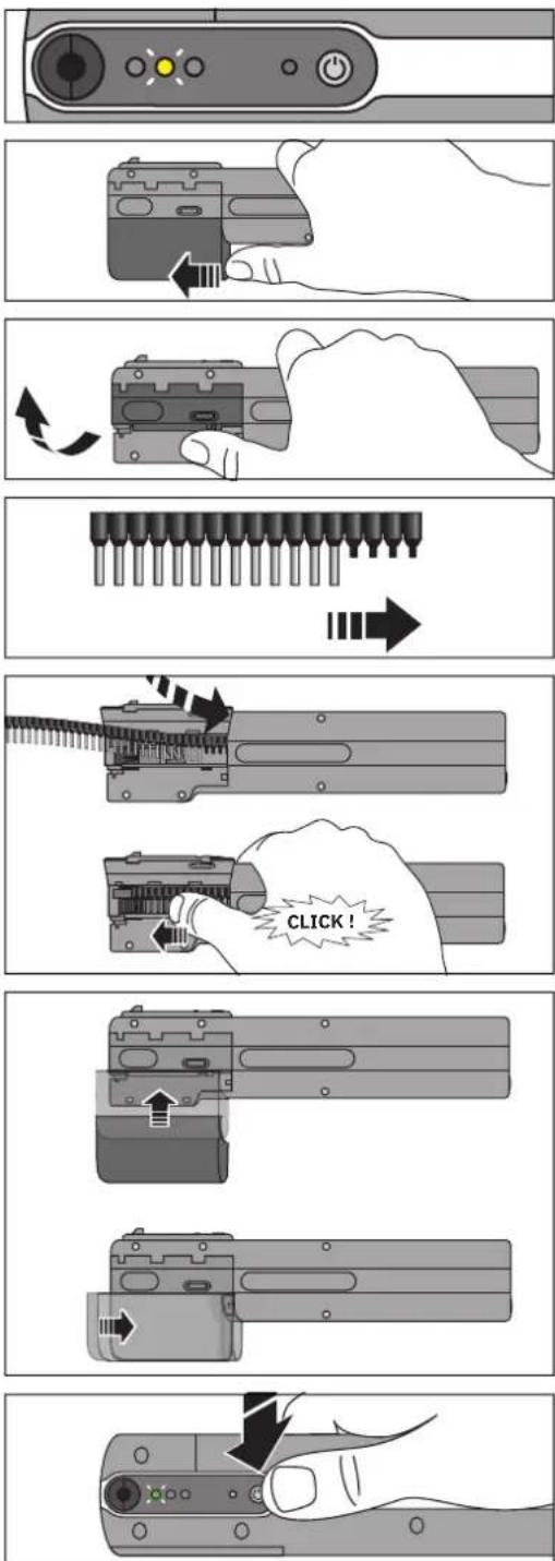
The yellow indicator light flashes.
- If the yellow indicator light is not flashing, do not insert a ferrule tape under any circumstances.
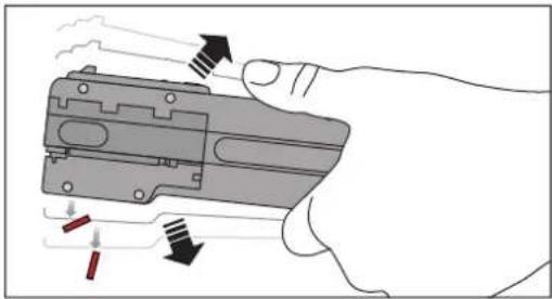
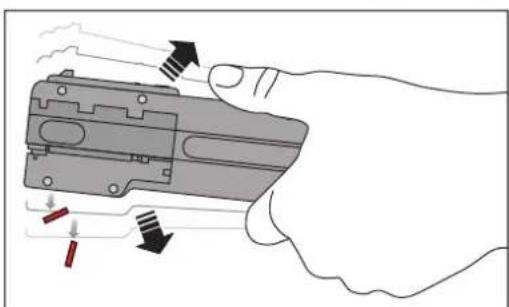
Removing the waste receptacle
- Using your thumb, slide the waste receptacle towards the front of the device and remove it with a downward motion.
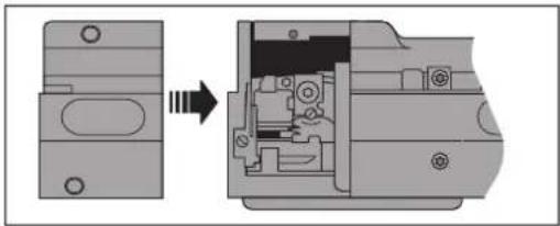
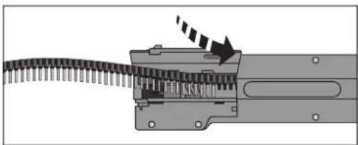
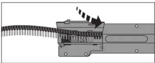
Opening the lid
- Flip the lid upwards to open. There will be slight resistance when doing this.
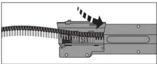
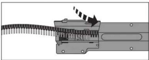
Inserting the ferrule tape

NOTE: Only use suitable ferrule tape (see page 11). These tapes have a function end that is required for error-free operation. Do not insert damaged or bent tapes.
- Insert the ferrule tape, starting with the function end (four plastic ferrules), as far as it will go to the right into the guide shaft.
- Then push the ferrule tape to the left as far as it will go into the guide shaft until it engages.
Closing the lid and attaching the waste receptacle
- Close the lid.
- When attaching the waste receptacle, place it so that it is flush with the lid (the waste receptacle will be around five millimeters over the front edge of the crimping tool).
- Push the waste receptacle into the end position parallel to the crimping tool until it snaps in and is flush with the front of the device.
Loading the ferrule tape
- Press the ON button.
→ You will hear a sound of movement and the green indicator light will flash. The crimping tool is ready for use.
3.5 Crimping
Cutting conductors to size
NOTE: Damage to the crimping tool
Make sure that the conductors are always cut straight. Do not use crimped, diagonally cut, or already stripped conductors.
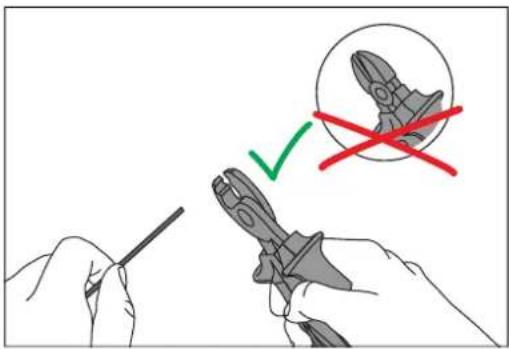
Only use cable cutters with sharp blades that cut the conductors and do not squeeze them. Do not use diagonal cutters or similar unsuitable tools.
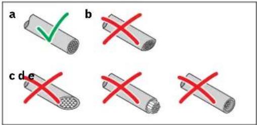
- Cut the conductor straight and cleanly with a CUTFOX 12 cable cutter.
a) Proper cut
b) Cut surface squeezed
c) Cut surface angled
d) Litz wires are longer than the insulation
e) Litz wires are shorter than the insulation
- Optionally, a cutting unit is available that is attached to the crimping tool (CF CRIMPHANDY CUTTER, 1212520).
Inserting the conductor
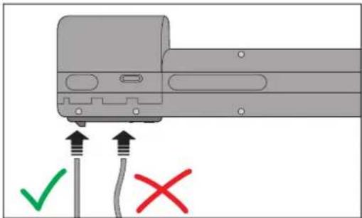
- Insert the conductor straight and without force into the shaft. It may be helpful to turn the conductor slightly around its own axis.
The conductor is processed. You will hear a crimping sound. As soon as the conductor is being processed, you must not pull or push at it.
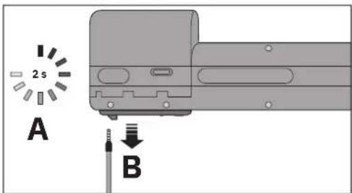
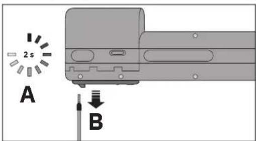
- When after approx. two seconds the process is concluded, pull the conductor out straight.
When the green indicator light flashes, the crimping tool is ready for use again.
We recommend checking the pull-out forces regularly. Check that ferrule and conductor are correctly crimped.
3.6 Loading the ferrule tape
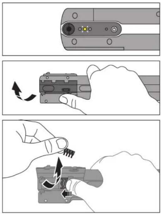
The yellow indicator light flashes. The ferrule magazine is empty.
- Remove the waste receptacle and dispose of the insulation remnants.
Opening the lid
- Flip the lid upwards to open. There will be slight resistance when doing this.
Removing the remnants of the tape
- Push the slide towards the front of the device.
- Hold the slide in this position and remove the remnants of the tape. Please make sure that the remnants of the tape do not fall into the guide shaft.
Inserting the ferrule tape
• See page 14.
3.7 Removing the battery

NOTE: Damage to the crimping tool
Never remove the battery during the crimping process or troubleshooting. The conductor should be taken out before the battery is removed.
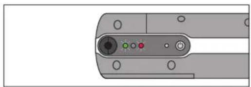
natural_image
Close-up of a mechanical component with a central circular button and three colored indicators (green, red, black) on its surface (no text or symbols visible)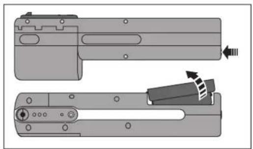
natural_image
Technical diagram of a mechanical component with two views, showing internal parts and directional arrows (no text or symbols)The green and red indicator lights flash simultaneously at short intervals. The battery is empty and has to be charged.
Unlocking the battery compartment
- Press the release button on the bottom of the crimping tool. The battery springs into the removal position.
- Remove the battery from the crimping tool.
Charging the battery
• See page 12.
4 Troubleshooting
NOTE: Damage to the crimping tool
Faults, such as a jammed conductor, can be remedied using the steps described below.
Never remove the battery during troubleshooting.
You may open the service cover to shake out loose parts. Do not loosen the screws of the housing to open it. This can damage the crimping tool.
4.1 Overview of possible faults
| Fault Cause Remedy | ||
| Device will not switch on – Problems with the power supply – Check the battery | – Clean the battery compartment | |
| The green indicator light flashes, but the device does not trip or the conductor cannot be inserted | – The battery was removed during a crimping cycle– Problems with the power supply– The conductor is not recognized– The crimping unit has been shifted manually | – Initialize the device (see page 27) |
| The green indicator light flashes, but there is still a conductor in the device | – The conductor was not correctly prepared (see page 15)– The conductor was inserted with too much force– The conductor was pulled out too early– The conductor does not correspond to the specifications | – Carefully turn the conductor and pull it out |
| – The battery was removed during the crimping process | – Screw in the service tool and remove the conductor– Then initialize the device (see page 27) | |
| The green and red indicator lights flash slowly, but the conductor is correct | – The conductor is not recognized– The conductor is recognized as having an incorrect cross-section | – Switch off the device without the conductor, and then switch on again– Check the stranding of the wires– Check if the conductor corresponds to the specifications– Check the temperature range |
| Errors re-occur several times – | The conductor does not correspond to the specifications | – Check if the conductor corresponds to the specifications |
| – Wear of the stripping bladeIndications for wear of the blade are rough and asymmetrical cut edges on the insulation remnants in the waste receptacle | – Please contact Phoenix Contact | |
| – The conductor was not correctly prepared (see page 15). | – Prepare the conductor according to specifications | |
4.2 Meaning of the indicator lights
| Green Yellow Red Meaning or action For remedy see | |||||
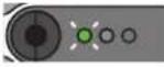 | Long flashing | -- Ready for operation - | |||
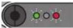 | Short flashing | - | Short flashing | Rechargeable battery is dead page 16 | |
 | Long flashing | - | Long flashing | Conductor cross-section is too small or too big - | |
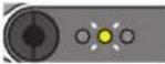 | - | Long flashing | - Insert the ferrule tape. Press the ON switch. page 14 | ||
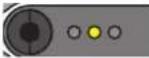 | - On - | Remove the ferrule tape. If none is inserted, actuate the tape slide. | page 23 | ||
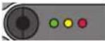 | On | On | On | A conductor is stuck in the crimping tool. Screw in the service tool on the threaded side and remove the conductor. | page 21 |
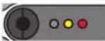 | - On | On | Press the reset button. - | ||
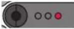 | -- On | Check if a ferrule without conductor is stuck in the crimping tool. To do so, push in the service tool on the plastic side until the red indicator light goes out. Then carefully remove the service tool. | page 22 | ||
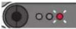 | - | - | Long flashing | Open the service cover. Remove loose parts from the device and close the service cover again.Remove any conductor that is stuck in the device.Screw in the service tool on the threaded side and remove the conductor.Remove the service tool. Press the ON switch. | page 25 |
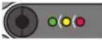 | Running light | No action is required if the running light appears briefly. If the running light appears continuously, start initializing the device. If this does not work, please contact Phoenix Contact. | page 27 | ||
4.3 Troubleshooting sequences
The diagram of the sequences is to provide you with an overview. The crimping tool guides the user through the entire troubleshooting procedure.
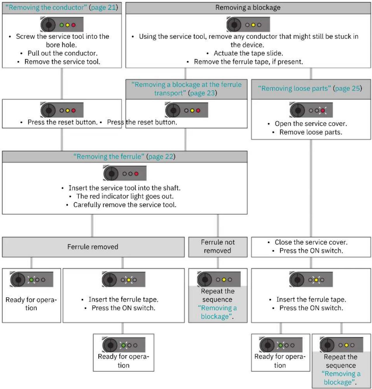
flowchart
graph TD
    A[""Removing the conductor" (page 21)"] --> B["Screw the service tool into the bore hole. Pull out the conductor. Remove the service tool."]
    C["Removing a blockage"] --> D["Using the service tool, remove any conductor that might still be stuck in the device. Actuate the tape slide. Remove the ferrule tape, if present."]
    B --> E[""Press the reset button. Press"]
    D --> F[""Removing a blockage at the ferrule transport" (page 23)"]
    F --> G["the reset button."]
    G --> H["Ferrule removed"]
    H --> I["Ready for operation"]
    H --> J["Insert the service tool into the shaft. The red indicator light goes out. Carefully remove the service tool."]
    I --> K["Ready for operation"]
    J --> L["Insert the ferrule tape. Press the ON switch."]
    L --> M["Repeat the sequence 'Removing a blockage'"]
    M --> N["Repeat the sequence 'Removing a blockage'"]
    N --> O["Ready for operation"]
    N --> P["Repeat the sequence 'Removing a blockage'"]
    O --> Q["Close the service cover. Press the ON switch."]
    P --> R["Insert the ferrule tape. Press the ON switch."]
4.4 Removing the conductor
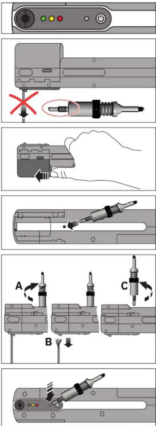
The three indicator lights light up simultaneously.
Following crimping, the conductor cannot be removed from the crimping tool.
• Take the service tool from the storage case.
Removing the waste receptacle
- Using your thumb, slide the waste receptacle towards the front of the device and remove it with a downward motion.
Screwing in the service tool and removing the conductor
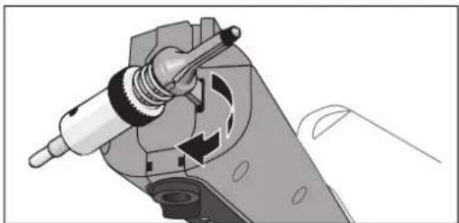
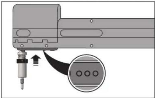
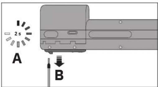
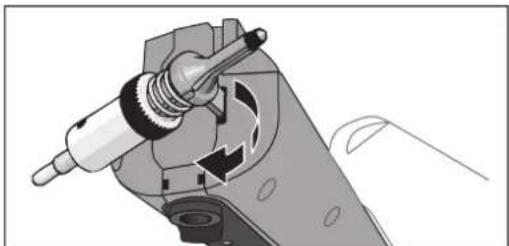
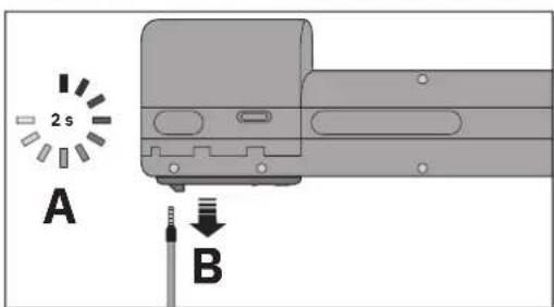
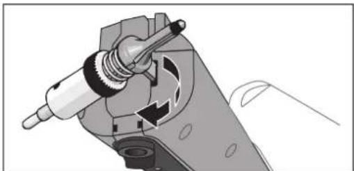
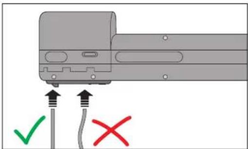
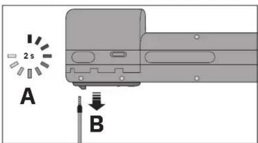
On the bottom of the crimping tool you will see a bore hole with an inner thread.
NOTE: While the service tool is screwed in, do not press the reset button under any circumstances. This will damage the crimping tool.
- Screw the service tool with the thread into the bore hole as far as it will go. Make sure that the service tool is not screwed too tight.
- Now carefully remove the conductor from the shaft.
- Unscrew the service tool again.
- Reattach the waste receptacle (see page 14).
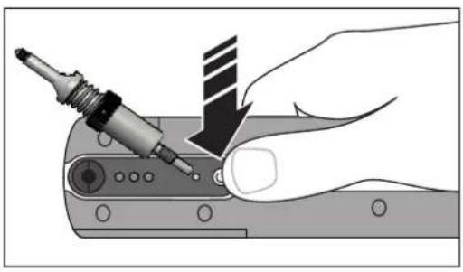
→ The yellow and red indicator lights light up.
- Press the reset button with the service tool.
If the red indicator light lights up, follow the sequence for removing a ferrule from the shaft (see page 22).
4.5 Removing the ferrule
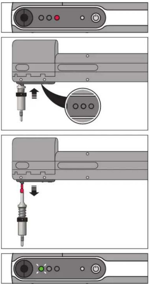
The red indicator light lights up.
Inserting the service tool in the shaft
- Insert the service tool with the plastic side straight into the shaft as far as it will go.
- Press in the spring until the red indicator light goes out.
• Carefully pull the service tool out straight.
If there was a ferrule in the crimping die, it sticks to the service tool.
It is possible that no ferrule has been caught. The crimping tool detects this and continues with further measures for remedying the fault.
If the green indicator light flashes, the crimping tool is ready.
If the yellow indicator light flashes, no ferrule could be removed. Follow the sequence for removing loose parts from the device (see page 25).
4.6 Removing a blockage at the ferrule transport
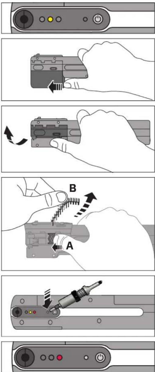
The yellow indicator light lights up. There is a mechanical blockage in the ferrule transport.
Removing the waste receptacle
- Using your thumb, slide the waste receptacle towards the front of the device and remove it with a downward motion.
Opening the lid
- Flip the lid upwards to open. There will be slight resistance when doing this.
Removing the ferrule tape
- Push the slide towards the front of the device.
- Hold the slide in this position and remove the ferrule tape.
• Always actuate the slide even if no tape was inserted.

NOTE: No ferrule tape may remain in the device.
→ The yellow and red indicator lights light up.
- Press the reset button with the service tool.
→ The red indicator light lights up.
If the red indicator light flashes, follow the sequence for removing loose parts (see page 25, from "Taking off the service cover").
natural_image
Diagram of a mechanical component with a screw and connector, showing a close-up inset of three circular ports (no text or symbols)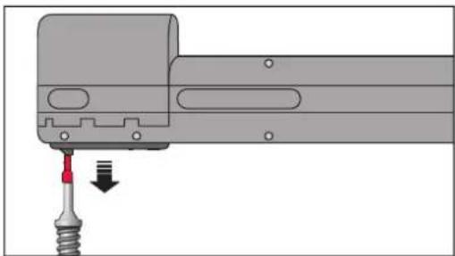
natural_image
Mechanical assembly diagram showing a tool inserted into a component with a red arrow indicating direction (no text or symbols present)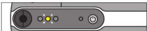
natural_image
Close-up of a device control panel with buttons and indicator lights (no text or symbols visible)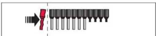
natural_image
Mechanical assembly diagram showing a chain being inserted into a motor (no text or symbols visible)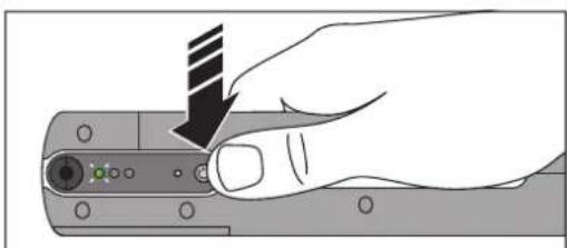
natural_image
Hand holding a computer mouse with a black arrow pointing to the handle (no text or symbols visible)Inserting the service tool in the shaft
- Insert the service tool with the plastic side straight into the shaft as far as it will go.
• Press in the spring until the red indicator light goes out.
- Carefully pull the service tool out straight. If there was a ferrule in the crimping die, it now sticks to the service tool. It is possible that no ferrule has been caught. The crimping tool detects this and continues with further measures for remedying the fault.
→ The yellow indicator light flashes.
If the yellow indicator light flashes, no ferrule could be removed. Follow the sequence for removing loose parts from the device (see page 25).
Inserting the ferrule tape
• Check if the ferrule tape is damaged.
• Detach damaged ferrules from the tape.
• Reinsert the ferrule tape (see page 14).
• Reattach the waste receptacle (see page 14).
Loading the ferrule tape
- Press the ON button.
→ You will hear a sound of movement and the green indicator light will flash. The crimping tool is ready for use.
4.7 Removing loose parts

The yellow indicator light lights up.
Removing the waste receptacle
- Using your thumb, slide the waste receptacle towards the front of the device and remove it with a downward motion.
Opening the lid
- Flip the lid upwards to open. There will be slight resistance when doing this.
Removing the ferrule tape
- Push the slide towards the front of the device.
- Hold the slide in this position and remove the ferrule tape.
• Always actuate the slide even if no tape was inserted.

NOTE: No ferrule tape may remain in the device.
→ The red indicator light flashes.
Taking off the service cover
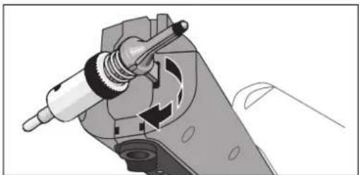
- Loosen the service cover with the service tool. For this, the service tool has a plastic protrusion that fits in a recess at the front side of the device. With a slight turning movement, pry open the service cover.
• Take off the service cover. The crimping tool turns off automatically.
natural_image
Illustration of a hand holding a mechanical device with arrows indicating motion or force (no text or symbols)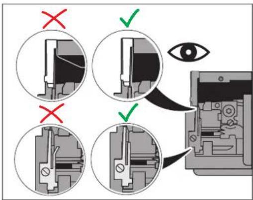
natural_image
Hand holding a computer mouse with a striped tip, pointing to the screen (no text or symbols visible)
natural_image
Pure diagram of a mechanical component with arrows indicating direction, no text or symbols present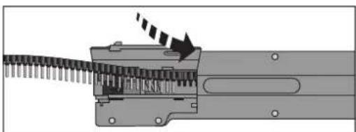
natural_image
Mechanical assembly diagram showing a gear-like component with a rotating shaft and directional arrow (no text or symbols)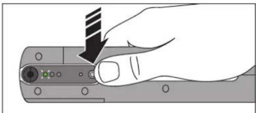
natural_image
Hand holding a mechanical component with a striped tool, no visible text or symbolsShaking out loose parts
- Check if there are any loose parts in the device.
- Shake the loose parts out of the device. Do not use any tool that could damage the crimping tool.
- If a conductor is still sticking in the device, remove it as described on page 21.
Checking the waste guide plates
- Check whether the two waste guide plates are undamaged.
- If a waste guide plate is bent, you must replace it (see page 28).
Switching on the crimping tool
• Reattach the service cover.
- Press the ON button.
→ The yellow indicator light flashes.
If the yellow indicator light lights up, follow the sequence for removing a blockage (see page 23).
Inserting the ferrule tape
- Check if the ferrule tape is damaged.
- Detach damaged ferrules from the tape.
- Reinsert the ferrule tape (see page 14).
- Reattach the waste receptacle (see page 14).
Loading the ferrule tape
- Press the ON button.
→ You will hear a sound of movement and the green indicator light will flash. The crimping tool is ready for use.
If the yellow indicator light lights up, follow the sequence for removing a blockage (see page 23).
4.8 Initializing the crimping tool (reset)
natural_image
Illustration of a hand using a screwdriver to adjust or install a component (no text or symbols visible)In exceptional cases, it is possible to initialize the device.
- Switch off the device.
- Hold the reset button pressed with the service tool.
- Press the ON button as well.
- Release the ON button first.
- Release the reset button.
The yellow indicator light lights up.
- Follow the sequence for removing loose parts from the device (see page 25).
- If this does not work, please contact Phoenix Contact.
4.9 Replacing the waste guide plates
Checking the unit version
- Check which type of waste guide plate is installed in your crimping tool. You can only replace waste guide plates from newer devices. Older devices must be sent to Phoenix Contact. There the device is retrofitted to conform to the current version.
Checking the waste guide plates
- Check whether the two waste guide plates are undamaged.
- If a waste guide plate is bent, you must replace it.
- Ordering data for the upper waste guide plate (GP2) CF CRIMPHANDY 0,5/GP2, 1212515 CF CRIMPHANDY 0,75/GP2, 1212516 CF CRIMPHANDY 1,0/GP2, 1212517 CF CRIMPHANDY 1,5/GP2, 1212844
- Ordering data for the lower waste guide plate (GP1) CF CRIMPHANDY/GP1, 1212514
4.9.1 Replacing waste guide plate GP1
natural_image
Mechanical assembly diagram showing internal components and a magnified view of a mechanical component (no text or symbols)Removing residual insulation
- Check if there is still residual insulation under waste guide plate GP1.
natural_image
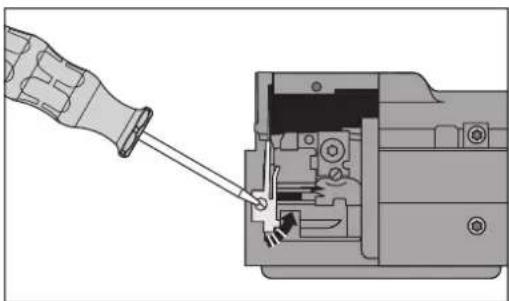
Diagram showing a hand inserting a screwdriver into an internal mechanical component (no text or symbols visible)Removing waste guide plate GP1
- Release the screw from the waste guide plate.
- Remove the waste guide plate.
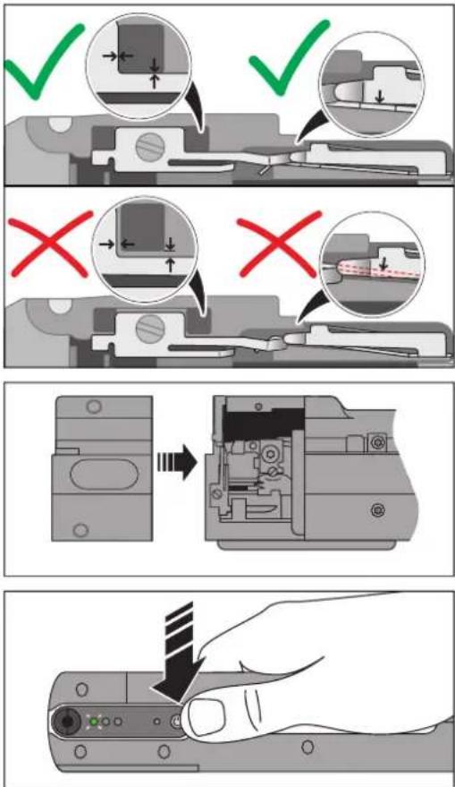
Inserting new waste guide plate GP1
- Insert the new waste guide plate.
Ordering data: CF CRIMPHANDY/GP1, 1212514 - Check for proper fitting in the slot.
- Re-tighten the screw.
Attaching the service cover
- Put the service cover on again.
Loading the ferrule tape
- Press the ON button.
You will hear a sound of movement and the green indicator light will flash. The crimping tool is ready for use.
If the yellow indicator light flashes, insert a ferrule tape (see page 14).
If the yellow indicator light lights up, follow the sequence for removing a blockage (see page 23).
4.9.2 Replacing waste guide plate GP2
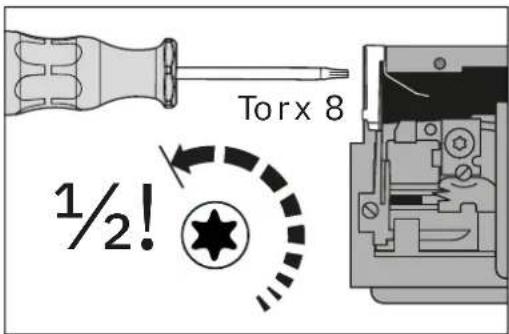
Removing the screws
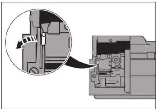
NOTE: If you screw out the screw too far, the crimping tool will be damaged. A half turn is sufficient to release the waste guide plate.
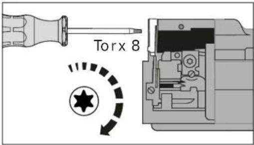
- Loosen the screw with a Torx 8 screwdriver by exactly half of a rotation.
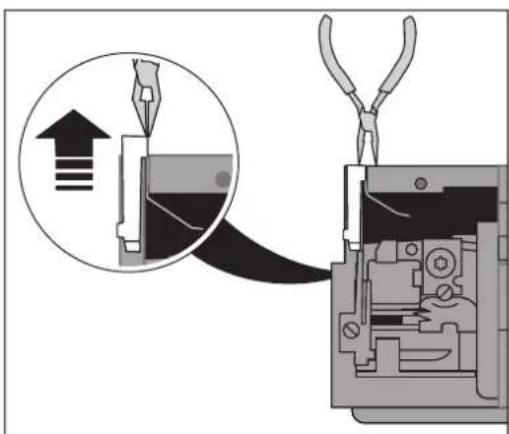
Removing the waste guide plate
- Pull out the waste guide plate with a needle-nose pliers.
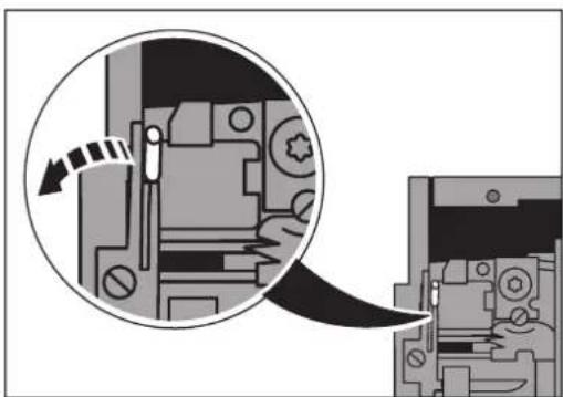
natural_image
Mechanical assembly diagram showing a close-up of a component with an arrow indicating rotation (no text or symbols present)Removing residual insulation
- Check if there is still residual insulation under waste guide plate GP1.
natural_image
Illustration of a hand holding a device with arrows indicating movement or force (no text or symbols present)Shaking out loose parts
- Check if there are any loose parts in the device.
- Shake the loose parts out of the device. Do not use any tool that could damage the crimping tool.
natural_image
Mechanical assembly diagram showing a component being cut into a housing (no text or symbols visible)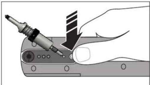
natural_image
Illustration of a hand using a power tool to adjust or install a component, with no visible text or symbols.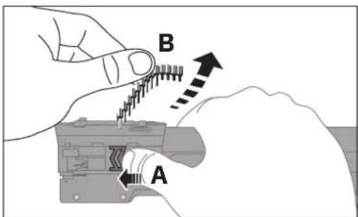
natural_image
Mechanical assembly diagram showing a piston and crank mechanism (no text or labels)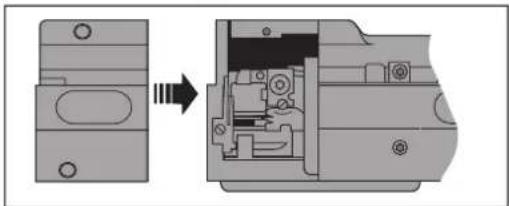
natural_image
Mechanical assembly diagram showing a component being processed into a assembled housing (no text or symbols visible)Attaching the service cover
- Put on the service cover again when the device is switched off.
Initializing the crimping tool (reset)
Initialize the device so that it returns to the initial position.
The device must be switched off.
- Hold the reset button pressed with the service tool.
- Press the ON button as well.
- Release the ON button first.
- Release the reset button.
→ The yellow indicator light lights up.
Removing the ferrule tape
- Push the slide towards the front of the device.
- Hold the slide in this position and remove the ferrule tape.
• Always actuate the slide even if no tape was inserted.
NOTE: No ferrule tape may remain in the device.
Taking off the service cover
• Take off the service cover. The crimping tool turns off automatically.
Attaching the service cover
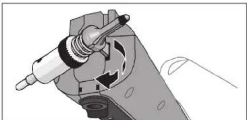
- Put on the service cover again when the device is switched off.
natural_image
Cross-sectional diagram of a mechanical device showing internal components and a downward arrow (no text or symbols)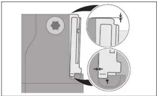
natural_image
Technical diagram showing mechanical assembly with cross-sectional views and dimension lines (no text or symbols)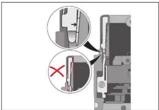
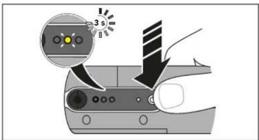
Switching on the crimping tool
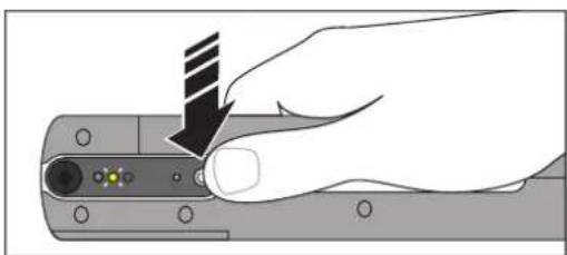
- Press the ON button.
After approx. three seconds, the yellow indicator light flashes.
Inserting the waste guide plate
• Take off the service cover. The crimping tool turns off automatically.
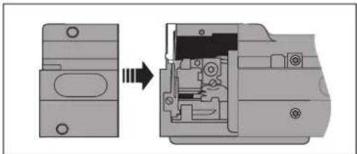
- Insert the new waste guide plate. Make sure you select the correct waste guide plate GP2 for your crimping tool.
Ordering data:
CF CRIMPHANDY 0,5/GP2, 1212515
CF CRIMPHANDY 0,75/GP2, 1212516
CF CRIMPHANDY 1,0/GP2, 1212517
CF CRIMPHANDY 1,5/GP2, 1212844
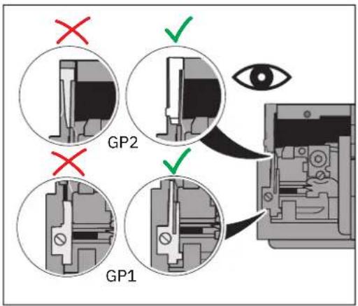
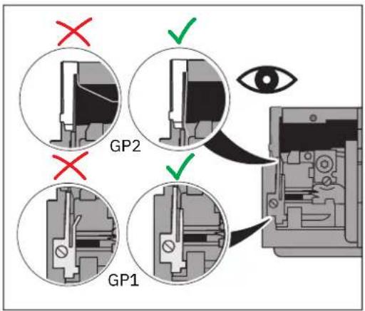
- The small lug must be on the small inclined surface. If the lug is pushed behind this surface, the new plate will be bent with its first use. (This lug is indicated in the lower magnifying glass with the single arrow.)
It is important that the waste guide plate is cleanly engaged and does not protrude from the housing frame.
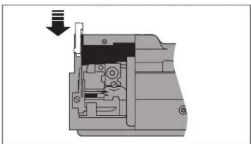
- Observe the position of the bracket of waste guide plate GP2.
natural_image
Diagram showing a mechanical assembly with an open component and a close-up view of internal components (no text or symbols)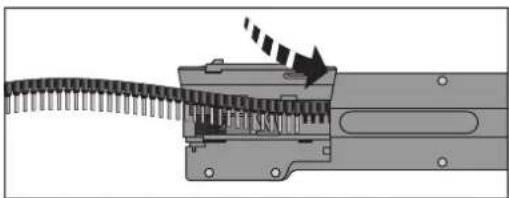
natural_image
Mechanical assembly diagram showing a gear-like component inserted into a housing with a directional arrow indicating motion (no text or symbols present)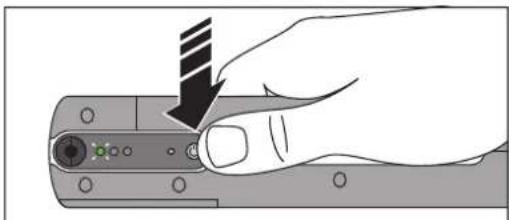
natural_image
Hand holding a device with a black arrow pointing to a button (no text or symbols visible)- Hold the waste guide plate in position.
- Retighten the screw.
Attaching the service cover
- Put the service cover on again.
Inserting the ferrule tape
- Reinsert the ferrule tape (see page 14).
- Reattach the waste receptacle (see page 14).
Loading the ferrule tape
- Press the ON button.
→ You will hear a sound of movement and the green indicator light will flash. The crimping tool is ready for use.
If the yellow indicator light lights up, follow the sequence for removing a blockage (see page 23).
4.10 Returning a product
When returning a product, please enclose a short description of how the fault occurred. We will also require incorrect results of crimping, insulation remnants, and one meter of the cable used.
A Appendix
A 1 Technical data
| Technical data for crimping tool | |
| Working cycle < 2 s | |
| Automatic shutdown After 5 min | |
| Crimping Square crimp | |
| Contact connection type Insulated ferrules of type AI...-8...-S | |
| Ferrule length 8 mm | |
| Ferrule capacity 50 pcs | |
| Insertion length of conductor 32 mm | |
| Conductor type H05V-K/H07V-K (see table below) | |
| Insulation type PVC | |
| Crimp cycles per battery charge Up to 3000 | |
| Ambient temperature, operating | +15°C ... +30°C |
| Dimensions (W x H x D) | 43 mm x 205 mm x 70 mm |
| Weight | 450 g |
| Noise emission L_pA | < 70 dB (A) |
| Work cycle trigger | Sensor |
| Controller | Electrical |
| Indicators | Indicator lights (LEDs) for status indication |
| Technical data for battery (CF CRIMPHANDY/ACCU, 1212518) | |
| Type | Lithium-ion battery |
| Voltage | 7.4 V DC |
| Nominal energy | 5.92 Wh |
| Capacity | 800 mAh |
| Technical data for charger (CF CRIMPHANDY/CHARGER, 1212519) | |
| Mains voltage | 100 V AC ... 240 V AC/50 Hz ... 60 Hz |
| Battery charging duration | 65 min approx./can be used after 20 min |
| Output | 8.4 V DC/0.8 A/6.72 W |
| Ambient temperature, operating | +5°C ... +40°C |
| Device type Metric conductor cross-section Outside diameter Conductor type | |||
| CF CRIMPHANDY 0,5 | 0.5 mm^2 | 1.7 mm ... 2.4 mm | H05V-K |
| CF CRIMPHANDY 0,75 | 0.75 mm^2 | 1.9 mm ... 2.6 mm | H05V-K |
| CF CRIMPHANDY 1,0 | 1.0 mm^2 | 2.0 mm ... 2.7 mm | H05V-K |
| CF CRIMPHANDY 1,5 | 1.5 mm^2 | 2.4 mm ... 3.1 mm | H07V-K |
A 2 Ordering data
Portable crimping tool
| Description Designation Item No. | ||
| Portable crimping tool | ||
| For a cross-section of 0.5 mm2 | CF CRIMPHANDY 0,5 | 1212463 |
| For a cross-section of 0.75 mm2 | CF CRIMPHANDY 0,75 | 1212464 |
| For a cross-section of 1.0 mm2 | CF CRIMPHANDY 1,0 | 1212465 |
| For a cross-section of 1.5 mm2 | CF CRIMPHANDY 1,5 | 1212466 |
Accessories
| Description Designation Item No. | ||
| Battery | CF CRIMPHANDY/ACCU | 1212518 |
| Charger | CF CRIMPHANDY/CHARGER | 1212519 |
| Cable cutter, for copper and aluminum up to 12 mm diameter (up to 35 mm^2 ) | CUTFOX 12 | 1212128 |
| Cutting unit, for CF CRIMPHANDY..., for stranded copper conductors from 0.5 mm^2 - 1.5 mm^2 , incl. waste receptacle | CF CRIMPHANDY CUTTER | 1212520 |
Replacement parts
| Description Designation Item No. | ||
| Replacement service tool | ||
| For CF CRIMPHANDY 0,5 | CF CRIMPHANDY 0,5/SERVICE-TOOL | 1212787 |
| For CF CRIMPHANDY 0,75 | CF CRIMPHANDY 0,75/SERVICE-TOOL | 1212786 |
| For CF CRIMPHANDY 1,0 | CF CRIMPHANDY 1,0/SERVICE-TOOL | 1212759 |
| For CF CRIMPHANDY 1,5 | CF CRIMPHANDY 1,5/SERVICE-TOOL | 1212708 |
| Replacement waste receptacle, for CF CRIMPHANDY... | CF CRIMPHANDY/COVER | 1212709 |
Description Designation Item No.
| Replacement waste guide plate GP1, for CF CRIMPHANDY... (see page 28) | CF CRIMPHANDY/GP1 1212514 |
Replacement waste guide plate GP2 (see page 28)
| For CF CRIMPHANDY 0,5 CF CRIMPHANDY 0,5/GP2 1212515 |
| For CF CRIMPHANDY 0,75 CF CRIMPHANDY 0,75/GP2 1212516 |
| For CF CRIMPHANDY 1,0 CF CRIMPHANDY 1,0/GP2 1212517 |
| For CF CRIMPHANDY 1,5 CF CRIMPHANDY 1,5/GP2 1212844 |
Ferrule tape
| Color code in accordance with DIN 46228-4/UL 486F | Color code in accordance with NF C 63-023 | Special color |
Ferrule tape, 8 mm, with plastic sleeve, dimensions in accordance with DIN 46228-4/UL 486F, 20 strips, 50 pieces per strip
| 0.5 mm ^2 , forCF CRIMPHANDY 0,5 | AI 0,5-8 WH-S, 1212521;color: white | AI 0,5-8 WH-S, 1212521;color: white | AI 0,5-8 OG-S, 1212784;color: orange |
| 0.75 mm ^2 , forCF CRIMPHANDY 0,75 | AI 0,75-8 GY-S, 1212522;color: gray | AI 0,75-8 BU-S, 1212785;color: blue | AI 0,75-8 WH-S, 1212783;color: white |
| 1.0 mm ^2 , forCF CRIMPHANDY 1,0 | AI 1,0-8 RD-S, 1212523;color: red | AI 1,0-8 RD-S, 1212523;color: red | AI 1,0-8 YE-S, 1212782;color: yellow |
| 1.5 mm ^2 , forCF CRIMPHANDY 1,5 | AI 1,5-8 BK-S, 1212524;color: black | AI 1,5-8 BK-S, 1212524;color: black | AI 1,5-8 RD-S, 1212781;color: red |
A 3 EU declaration of conformity
EU declaration of conformity
No. 000777344_02
Manufacturers Phoenix Contact GmbH & Co.KG
Address Flachsmarktstraße 8, 32825 Blomberg, Germany
Product designation CF CRIMPHANDY 0,5
Item No. 1212463
This declaration of conformity is issued under the sole responsibility of the manufacturer. The products specified in this declaration are in conformity with the following relevant harmonization legislation:
2006/42/EC
Machinery Directive (MD)
(OJ No. L157, 9 June 2006)
2011/65/EU
Restriction on the use of certain hazardous substances (RoHS)
(OJ No. L174, 1 July 2011)
2014/30/EU
EMC Directive (electromagnetic compatibility)
(OJ No. L96, 29 March 2014)
The following pertinent standards have been applied for the assessment of conformity:
EN 60335-1:2012+ AC:2014+ A11:2014+
EN IEC 55014-1:2021
A13:2017+ A1:2019+ A2:2019 + A14:2019+
A15:2021
EN IEC 55014-2:2021
EN IEC 61000-6-2:2019
EN IEC 62061:2021
EN IEC 63000:2018
EN ISO 12100:2010
EN ISO 13854:2019
EN ISO 13857:2019
The products listed below are also part of this EU declaration of conformity:
Item No. Product designation
1212464 CF CRIMPHANDY 0,75
1212465 CF CRIMPHANDY 1,0
1212466 CF CRIMPHANDY 1,5
Please observe the following notes
General Terms and Conditions of Use for technical documentation
Phoenix Contact reserves the right to alter, correct, and/or improve the technical documentation and the products described in the technical documentation at its own discretion and without giving prior notice, insofar as this is reasonable for the user. The same applies to any changes that serve the purpose of technical progress.
The receipt of technical documentation (in particular user documentation) does not constitute any further duty on the part of Phoenix Contact to furnish information on modifications to products and/or technical documentation. You are responsible to verify the suitability and intended use of the products in your specific application, in particular with regard to observing the applicable standards and regulations. All information made available in the technical documentation is supplied without any accompanying guarantee, whether expressly mentioned, implied or tacitly assumed.
In general, the provisions of the current General Terms and Conditions of Phoenix Contact apply exclusively, in particular as concerns any warranty liability.
This manual, including all illustrations contained herein, is copyright protected. Any changes to the contents or the publication of extracts of this document are prohibited.
Phoenix Contact reserves the right to register its own intellectual property rights for the product identifications of Phoenix Contact products that are used here. Registration of such intellectual property rights by third parties is prohibited.
Other product identifications may be afforded legal protection, even where they may not be indicated as such.
How to contact us
Internet
Up-to-date information on Phoenix Contact products and our Terms and Conditions can be found on the Internet at: phoenixcontact.com
Make sure you always use the latest documentation. It can be downloaded at: phoenixcontact.com/products
Subsidiaries
If there are any problems that cannot be solved using the documentation, please contact your Phoenix Contact subsidiary. Subsidiary contact information is available at phoenixcontact.com.
Published by Phoenix Contact GmbH & Co. KG
Should you have any suggestions or recommendations for improvement of the contents and layout of our manuals, please send your comments to: tecdoc@phoenixcontact.com
Instructions de service originales
natural_image
Mechanical assembly diagram showing two views of a tool handle with directional arrows indicating movement (no text or symbols)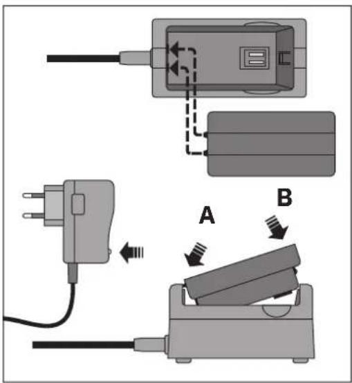
natural_image
Hand holding a handheld electronic device with a circular button and indicator lights (no text or symbols visible)natural_image
Close-up of a device control panel with buttons and indicator lights (no text or symbols visible)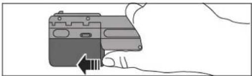
natural_image
Illustration of a hand holding a camera with a right-hand rule arrow (no text or symbols)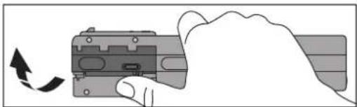
natural_image
Hand holding a mechanical component with an arrow indicating rotation (no text or symbols)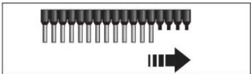
natural_image
Diagram of a row of 10-pin integrated circuits with an arrow pointing to one (no text or symbols present)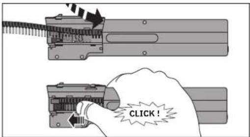
natural_image
Two mechanical components with arrows indicating movement or assembly, no visible text or symbols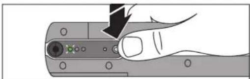
natural_image
Hand holding a device with a black arrow pointing to a button (no text or symbols visible)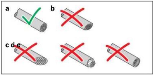
natural_image
Close-up of a mechanical component with a central circular button and three colored indicators (green, red, black) on its surface (no text or symbols visible)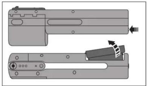
natural_image
Technical illustration of a mechanical component with two views, showing internal parts and directional arrows (no text or symbols)natural_image
Diagram of a mechanical component with a screw and connector, showing a close-up inset of three circular components (no text or symbols)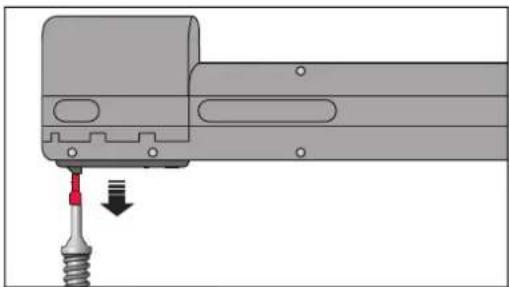
natural_image
Mechanical assembly diagram showing a tool inserted into a component with a red arrow indicating direction (no text or symbols present)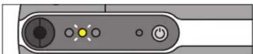
natural_image
Close-up of a device control panel with buttons and indicator lights (no text or symbols visible)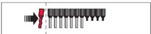
natural_image
Mechanical assembly diagram showing a chain being inserted into a motor (no text or symbols visible)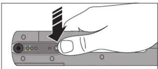
natural_image
Hand holding a computer mouse with a black arrow pointing to the handle (no text or symbols visible)natural_image
Illustration of a hand holding a mechanical component with arrows indicating motion or force direction (no text or symbols)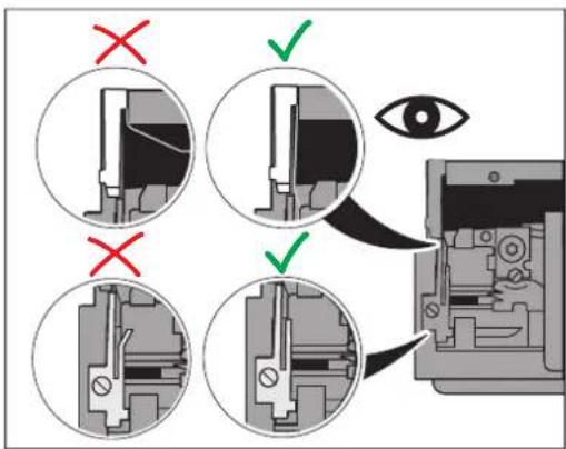
natural_image
Hand holding a computer mouse with a striped tip, pointing to the screen (no text or symbols visible)
natural_image
Pure diagram of a mechanical component with arrows indicating direction, no text or symbols present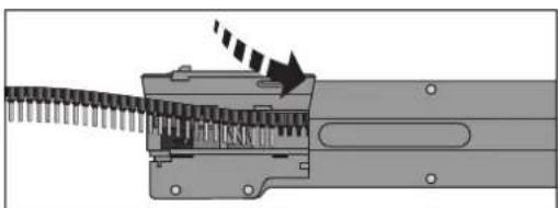
natural_image
Mechanical assembly diagram showing a gear-like component with a rotating shaft and directional arrow (no text or symbols)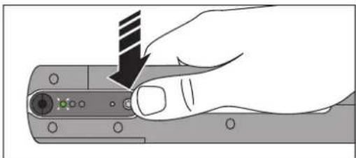
natural_image
Hand holding a mechanical component with a striped tool, no visible text or symbolsnatural_image
Illustration of a hand using a screwdriver to adjust a mechanical component (no text or symbols visible)natural_image
Mechanical assembly diagram showing internal components and a magnified view of a mechanical component (no text or symbols)natural_image
Diagram showing a hand inserting a cable into an internal device (no text or symbols visible)natural_image
Mechanical assembly diagram showing a close-up of a mechanical component with an arrow indicating rotation (no text or symbols present)natural_image
Illustration of a hand holding a device with arrows indicating motion or force (no text or symbols)natural_image
Mechanical assembly diagram showing a component being cut into a housing (no text or symbols visible)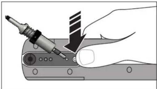
natural_image
Illustration of a hand using a power tool to adjust or install a component, with no visible text or symbols.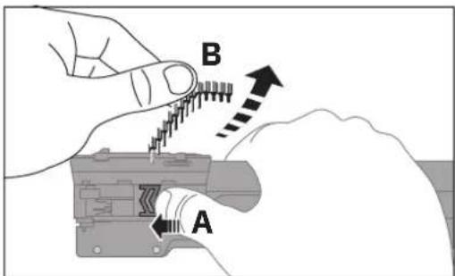
natural_image
Mechanical assembly diagram showing a valve mechanism with rotating components (no text or labels)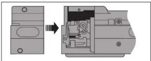
natural_image
Mechanical assembly diagram showing a part before and after disassembly, with no visible text or symbols.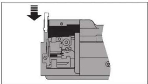
natural_image
Cross-sectional diagram of a mechanical device showing internal components and a downward arrow (no text or symbols)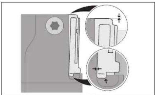
natural_image
Technical diagram showing mechanical assembly with cross-sectional views and dimension arrows (no text or labels)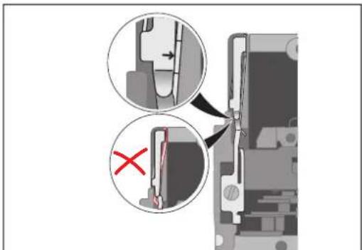
natural_image
Diagram showing a mechanical assembly with an open component and a close-up view of internal components (no text or symbols)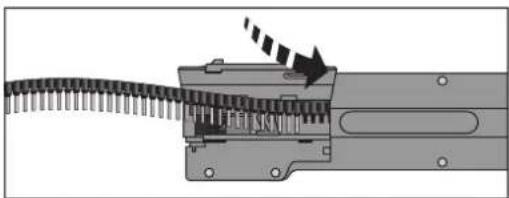
natural_image
Mechanical assembly diagram showing a gear-like component inserted into a housing with a directional arrow indicating motion (no text or symbols present)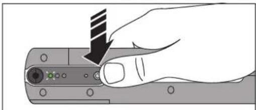
natural_image
Hand holding a device with a black arrow pointing to a button (no text or symbols visible)Directive relative aux machines
(OJ No. L157, 9 June 2006)
2011/65/EU
(OJ L 174, 1 July 2011)
2014/30/EU
(OJ L 96, 29 March 2014)
Valigetta con:
natural_image
Mechanical assembly diagram showing two views of a tool handle with directional arrows indicating movement (no text or symbols)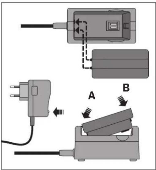
natural_image
Hand holding a handheld electronic device with a circular button and indicator lights (no text or symbols visible)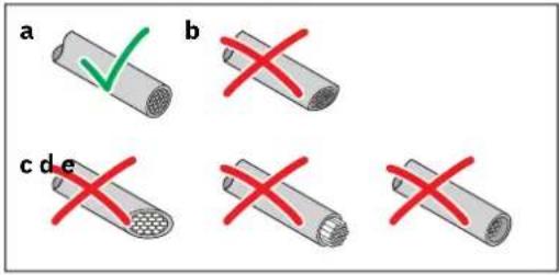
natural_image
Close-up of a mechanical component with three colored indicator lights (black, green, red) on a gray surface, no visible text or symbols.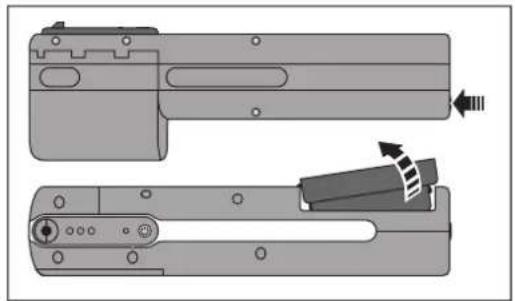
natural_image
Technical illustration of a mechanical component with two views, showing internal parts and directional arrows (no text or symbols)natural_image
Diagram of a mechanical component with a screw and connector, showing a close-up inset of three circular ports (no text or symbols present)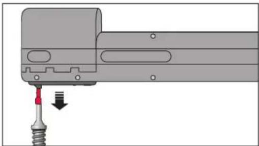
natural_image
Mechanical assembly diagram showing a tool inserted into a component with a red arrow indicating direction (no text or symbols present)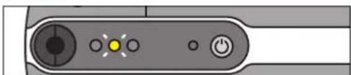
natural_image
Close-up of a device control panel with buttons and indicator lights (no text or symbols visible)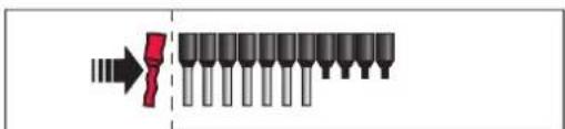
natural_image
Mechanical assembly diagram showing a chain being inserted into a motor (no text or symbols visible)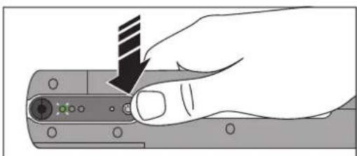
natural_image
Hand holding a computer terminal with a black arrow pointing to the button (no text or symbols visible)natural_image
Illustration of a hand holding a mechanical component with arrows indicating motion or force direction (no text or symbols)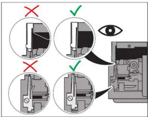
natural_image
Hand holding a computer mouse with a striped tip, pointing to the screen (no text or symbols visible)
natural_image
Pure diagram of a mechanical component with arrows indicating direction, no text or symbols present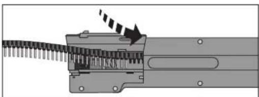
natural_image
Mechanical assembly diagram showing a gear-like component with a rotating shaft and directional arrow (no text or symbols)
natural_image
Hand holding a mechanical component with a striped tool, no visible text or symbolsnatural_image
Illustration of a hand using a screwdriver to adjust a mechanical component (no text or symbols visible)natural_image
Mechanical assembly diagram showing internal components and a magnified view of a mechanical part (no text or symbols)natural_image
Diagram showing a hand inserting a screwdriver into an internal mechanical component (no text or symbols visible)natural_image
Mechanical assembly diagram showing a close-up of a component with an arrow indicating rotation (no text or symbols present)natural_image
Illustration of a hand holding a device with arrows indicating movement or force (no text or symbols present)natural_image
Mechanical assembly diagram showing a component being cut into a housing (no text or symbols visible)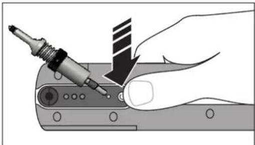
natural_image
Illustration of a hand using a power tool to adjust or install a component, with no visible text or symbols.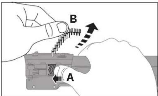
natural_image
Mechanical assembly diagram showing a valve mechanism with rotating components (no text or labels)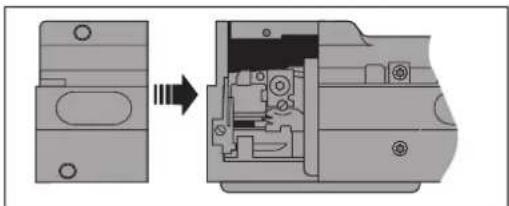
natural_image
Mechanical assembly diagram showing a component being extruded into a housing (no text or symbols present)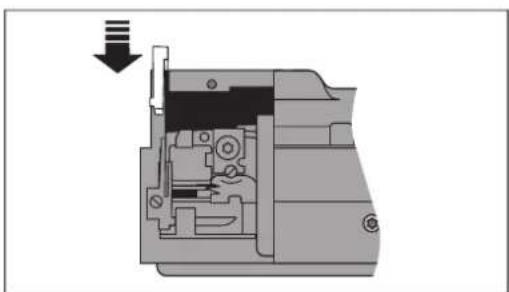
natural_image
Cross-sectional diagram of a mechanical device showing internal components and a downward arrow (no text or symbols)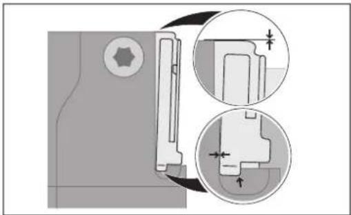
natural_image
Technical diagram showing mechanical assembly with cross-sectional views and dimension lines (no text or symbols)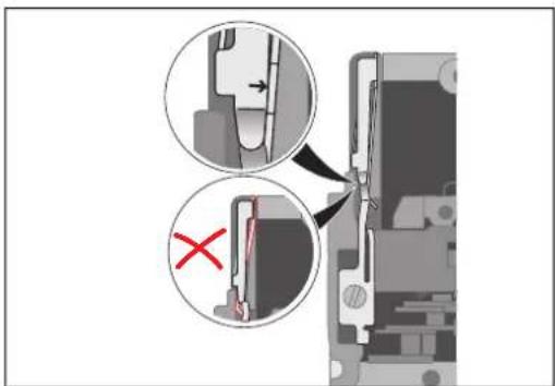
natural_image
Diagram showing a mechanical assembly with an open component and a close-up view of internal components (no text or symbols)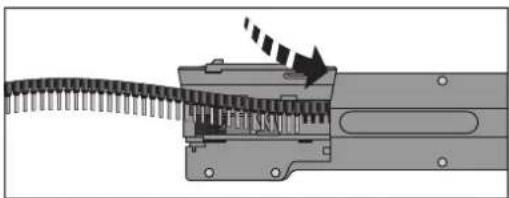
natural_image
Mechanical assembly diagram showing a gear-like component inserted into a housing with a directional arrow indicating motion (no text or symbols present)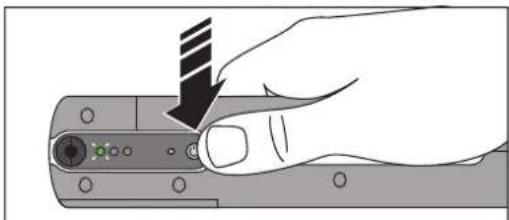
natural_image
Hand holding a device with a black arrow pointing to a button (no text or symbols visible)(OJ No. L157, 9 June 2006)
2011/65/UE
(OJ L 174, 1 July 2011)
2014/30/UE
(OJ L 96, 29 March 2014)
Maletín con:
natural_image
Mechanical assembly diagram showing two views of a tool handle with directional arrows indicating movement (no text or symbols)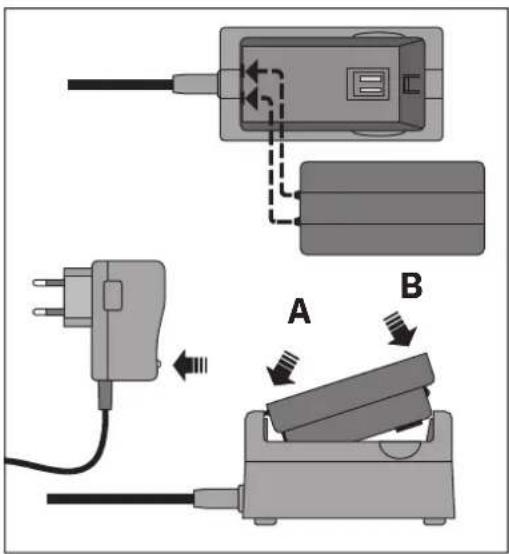
natural_image
Hand holding a handheld electronic device with a green indicator light (no text or symbols visible)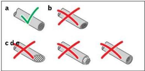
natural_image
Close-up of a mechanical component with three colored indicator lights (black, green, red) on its surface, no visible text or symbols.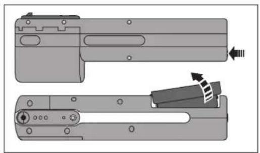
natural_image
Technical diagram of a mechanical component with two views, showing internal parts and directional arrows (no text or symbols)natural_image
Diagram of a mechanical component with a screw and connector, showing a close-up inset of three circular ports (no text or symbols)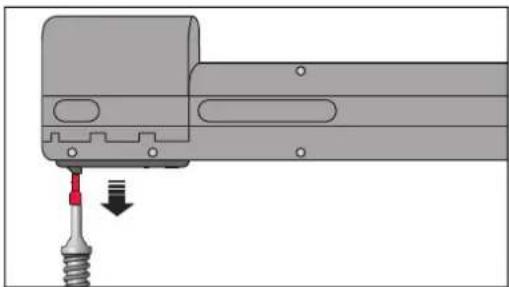
natural_image
Mechanical assembly diagram showing a tool inserted into a component with a red arrow indicating direction (no text or symbols present)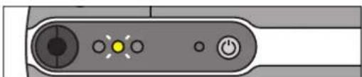
natural_image
Close-up of a device control panel with buttons and indicator lights (no text or symbols visible)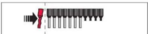
natural_image
Mechanical assembly diagram showing a chain being inserted into a motor (no text or symbols visible)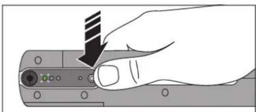
natural_image
Hand holding a computer mouse with a black arrow pointing to the handle (no text or symbols visible)natural_image
Illustration of a hand holding a mechanical component with arrows indicating motion or force direction (no text or symbols)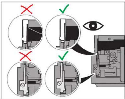
natural_image
Hand holding a computer mouse with a striped tip, pointing to the screen (no text or symbols visible)
natural_image
Pure diagram of a mechanical component with arrows indicating direction, no text or symbols present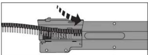
natural_image
Mechanical assembly diagram showing a gear-like component with a rotating shaft and directional arrow (no text or symbols)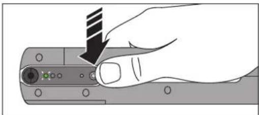
natural_image
Hand holding a mechanical component with a striped tool, no visible text or symbolsnatural_image
Illustration of a hand using a power tool to adjust or install a component, with no visible text or symbols.natural_image
Mechanical assembly diagram showing internal components and a magnified view of a mechanical component (no text or symbols)natural_image
Diagram showing a hand inserting a screwdriver into a device component (no text or symbols visible)natural_image
Mechanical assembly diagram showing a close-up of a component with a magnified inset view (no text or symbols)natural_image
Illustration of a hand holding a device with arrows indicating motion or force (no text or symbols)natural_image
Mechanical assembly diagram showing a component being cut into a housing (no text or symbols visible)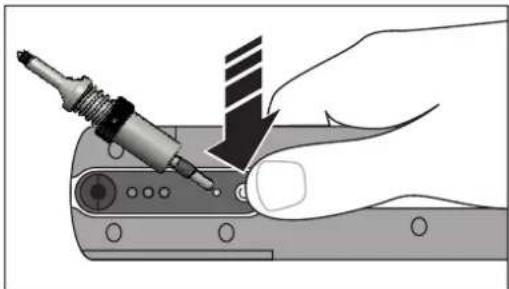
natural_image
Illustration of a hand using a power tool to adjust or install a component, with no visible text or symbols.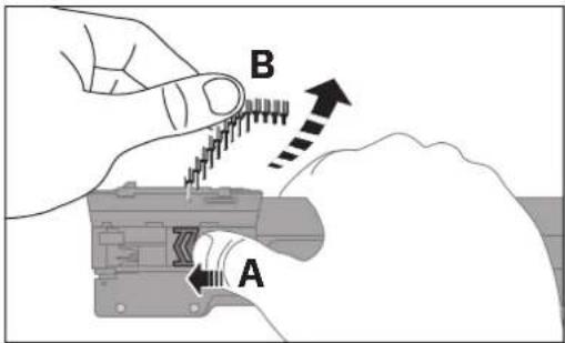
natural_image
Mechanical assembly diagram showing a valve mechanism with rotating components (no text or labels)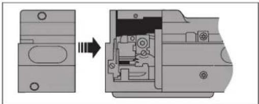
natural_image
Cross-sectional diagram of a mechanical assembly showing internal components and part alignment (no text or symbols)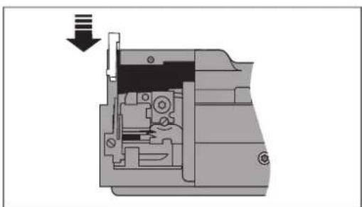
natural_image
Cross-sectional diagram of a mechanical device showing internal components and a downward arrow (no text or symbols)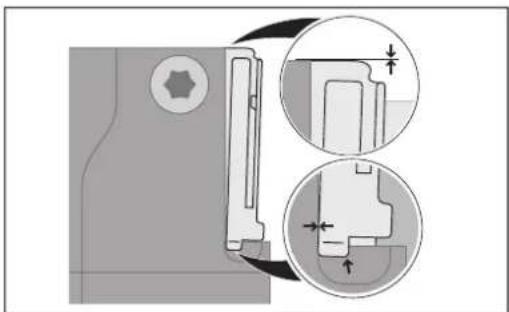
natural_image
Technical diagram showing mechanical assembly with cross-sectional views and dimension arrows (no text or labels)
natural_image
Diagram showing a mechanical assembly with an open component and a close-up view of internal components (no text or symbols)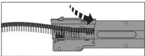
natural_image
Mechanical assembly diagram showing a gear-like component being inserted into a housing with a directional arrow indicating motion (no text or symbols present)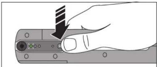
natural_image
Hand holding a device with a black arrow pointing to a button (no text or symbols visible)- CF CRIMPHANDY
- Akkufach entriegeln
- Leiter abschneiden
- Original operating instructions
- Operation of the portable CF CRIMPHANDY crimping tool
- Table of contents
- For your safety ....5
- Description of the crimping tool 9
- Operating the crimping tool 10
- Troubleshooting 17
- A Appendix 35
- For your safety
- Identification of warning notes
- DANGER
- WARNING
- CAUTION
- Qualification of users
- Field of application of the product
- NOTE: To ensure error-free use and the process reliability of the portable crimping tool, only use the conductors and ferrules described.
- Correct use of the battery and charger
- WARNING: Important safety notes for lithium-ion batteries Risk of short circuit, fire, explosion, electric shock, or damage to health
- Note the following when charging the battery
- Disposal
- Description of the crimping tool
- Scope of supply
- Necessary accessories
- Overview of the operating elements
- Crimping tool
- Operating the crimping tool
- Suitable conductors and ferrules
- Suitable conductors
- Wire check
- Suitable ferrules
- Preparing the conductor
- Quality of the crimping result
- Charging the battery
- Unlocking the battery compartment
- Charging the battery
- Inserting the battery in the crimping tool
- Switching on the crimping tool
- Switching on the crimping tool
- Troubleshooting
- Switching off the crimping tool
- Inserting the ferrule tape
- Removing the waste receptacle
- Opening the lid
- Inserting the ferrule tape
- Closing the lid and attaching the waste receptacle
- Loading the ferrule tape
- Crimping
- Cutting conductors to size
- NOTE: Damage to the crimping tool
- Inserting the conductor
- Loading the ferrule tape
- Removing the remnants of the tape
- Removing the battery
- Troubleshooting
- Overview of possible faults
- Troubleshooting sequences
- Removing the conductor
- Screwing in the service tool and removing the conductor
- Removing the ferrule
- Inserting the service tool in the shaft
- Removing a blockage at the ferrule transport
- Removing the ferrule tape
- Removing loose parts
- Taking off the service cover
- Shaking out loose parts
- Checking the waste guide plates
- • Reattach the service cover.
- Initializing the crimping tool (reset)
- Replacing the waste guide plates
- Checking the unit version
- Replacing waste guide plate GP1
- Removing residual insulation
- Removing waste guide plate GP1
- Inserting new waste guide plate GP1
- Attaching the service cover
- Replacing waste guide plate GP2
- Removing the screws
- Removing the waste guide plate
- Initializing the crimping tool (reset)
- Inserting the waste guide plate
- Returning a product
- A Appendix
- A 2 Ordering data
- A 3 EU declaration of conformity
- Please observe the following notes
- General Terms and Conditions of Use for technical documentation
- How to contact us
- Internet
- Subsidiaries
- Instructions de service originales
Brand : Phoenix Contact
Model : CF CRIMPHANDY
Category : Power tool