Profile PCDUS01KITFS - Dishwasher GE - Free user manual and instructions
Find the device manual for free Profile PCDUS01KITFS GE in PDF.

User questions about Profile PCDUS01KITFS GE
0 question about this device. Answer the ones you know or ask your own.
Ask a new question about this device
Download the instructions for your Dishwasher in PDF format for free! Find your manual Profile PCDUS01KITFS - GE and take your electronic device back in hand. On this page are published all the documents necessary for the use of your device. Profile PCDUS01KITFS by GE.
USER MANUAL Profile PCDUS01KITFS GE
Installation Instructions
Undersink Kit PCDUS01KITFS
ENGLISH / FRANÇAIS / ESPAÑOL
Questions? Call 833-4BODEWELL (833-426-3393) or visit our Website at: GEAppliances.com In Canada, call 1.800.561.3344 or visit our Website at: GEAppliances.ca
VIDEO
■ Use this video to aid in installing the dishwasher.
NOTE: These installation instructions, including all safety information, should be followed completely.

text_image
QR code image containing encoded data, no visible human-readable textBEFORE YOU BEGIN
Read these instructions completely and carefully.
- IMPORTANT – Save these instructions for local electrical inspector's use.
• IMPORTANT – Observe all governing codes and ordinances. - IMPORTANT – This kit is intended to be used only with PZF560 Series Profile Compact Dishwashers - See the Owner's Manual for details.
- Note to Installer – Be sure to leave these instructions with the Consumer.
- Note to Consumer – Keep these instructions for future reference.
• Installation must be performed by a qualified installer.
• Proper installation is the responsibility of the installer.
TOOLS YOU WILL NEED
Safety Glasses
Gloves

Drill and Bits (including 3/32" for pilot holes)
natural_image
Line drawing of a handheld electric drill with multiple drill bits (no text or symbols)M6 Allen Wrench
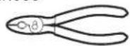
□ Pliers
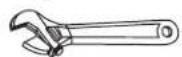
□ Adjustable Wrench

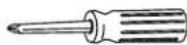
□ Phillips Screwdriver
Pencil

□ Level

□ Measuring Tape
WARNING
Disconnect power before installing. Failure to do so could injury or death.
CONTENTS
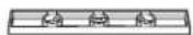
Frame
□ Bottom Frame
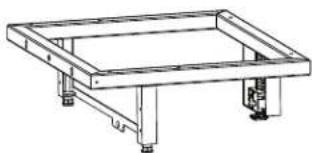
natural_image
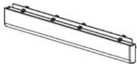
Technical line drawing of a rectangular frame structure with supports and legs (no text or symbols)□ Toekick Assembly
□ Decorative Toekick
☐ Type A - 1/2" Coarse Thread Screws (6)

☐ Type C - 1/2" Black Screws (4)

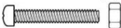
Type B - 1" Machine Screws and Nuts (2)
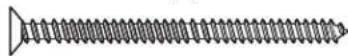
☐ Type D - 2-3/4" Wood Screws (2)
□ Leveler Fastener Nut (1)
Leveler Rod (1)

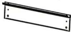
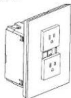
□ Junction Box, Cover and Conduit Hole Covers

natural_image
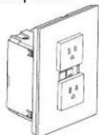
Technical line drawing of a rectangular enclosure with mounting holes and a separate view of a rectangular panel (no text or symbols)□ GFCI/AFCI Receptacle
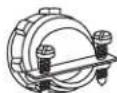
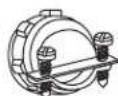
□ Strain Relief
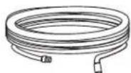
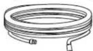
Drain Hose
WARNING
For your safety, the information in this manual must be followed to minimize the risk of fire, explosion, electric shock, and to prevent property damage, personal injury, or death.
WARNING

- ELECTRICAL SHOCK HAZARD
■ Plug into a grounded 3-prong outlet.
■ DO NOT use an adapter.
■ DO NOT remove ground prong.
■ DO NOT use an extension cord.
Failure to follow these instructions can result in death, fire or electrical shock.
ELECTRICAL REQUIREMENTS
CIRCUIT – Individual, properly polarized and grounded 15 or 20 amp circuit breaker or time-delay fuse.
POWER SUPPLY - 2 wire plus ground, 120 Volt, single phase, 60 Hz, alternating current.
Outlet Receptacle – Properly grounded 3-prong receptacle to be located so the power cord is accessible when the dishwasher is in position. If a 2-prong receptacle is present, it is the owner's responsibility to have a licensed electrician replace it with a properly grounded 3-prong grounding type receptacle.
Unit must be electrically grounded in accordance with local codes and ordinances, or in the absence of local codes, with latest edition of the NATIONAL ELECTRICAL CODE, ANSI/NFPA
NO. 70 or CANADIAN ELECTRICAL CODE, CSA C22.1. Check with a licensed electrician if you are not sure that the dishwasher is properly grounded.
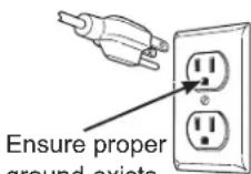
ground exists before use.
GROUNDING INSTRUCTIONS
This appliance must be grounded. In the event of malfunction or breakdown, grounding will reduce the risk of electric shock by providing a path of least resistance for electric current. This appliance is equipped with a cord having an equipment-grounding conductor and a grounding plug. The plug must be plugged into an appropriate outlet that is properly installed and grounded in accordance with all local codes and ordinances.
WARNING
Improper connection of the equipment-grounding conductor can result in a risk of electrical shock.
Check with a qualified electrician, or service representative or personnel, if you are in doubt as to
whether the appliance is properly grounded. DO NOT modify the plug on the power supply cord. If it will not fit the outlet, have a proper outlet installed by a qualified electrician.
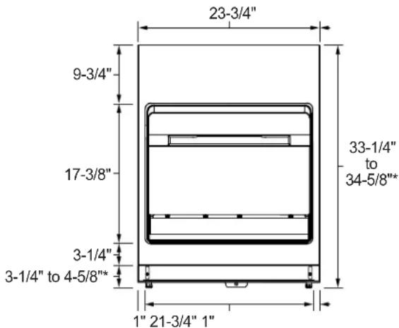
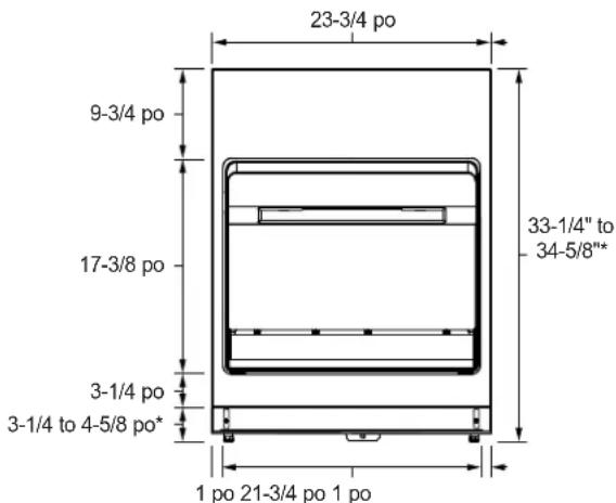
PRODUCT DIMENSIONS
text_image
23-3/4" 9-3/4" 17-3/8" 3-1/4" 3-1/4" to 4-5/8"* 1" 21-3/4" 1" 33-1/4" to 34-5/8"**1-3/8" - Leg Height Adjustment
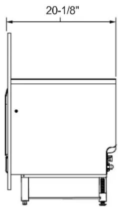
text_image
20-1/8"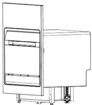
natural_image
Technical line drawing of a mechanical device with a rectangular panel and mounting base (no text or symbols)PREPARE DISHWASHER ENCLOSURE
WARNING
To reduce the risk of electric shock, fire, or injury to persons, the installer must ensure that the dishwasher is completely enclosed at the time of installation.
■ The rough cabinet opening must be at least 24" deep, 24" wide and approximately 34-1/4" ± 1/4" height.
■ This dishwasher fits under a special sink with a depth of 6" or less in a 1-1/2" countertop.
■ The dishwasher must be installed so that drain hose is no more than 10' in length for proper drainage.
■ The dishwasher must be fully enclosed on the top, sides and back, and must not support any part of the enclosure.
Cabinet Preparation and Wire Routing
■ The power supply receptacle for the appliance should be installed in a cabinet or on a wall adjacent to the under-sink or built-in space in which the appliance is to be installed.
■ There should be an opening through the partition that is large enough for the attachment plug to pass through. The longest dimension of the opening should not be larger than 1-1/2".
■ The edges of the opening should be smooth and rounded if the partition is wood. If the cabinet wall is metal, the hole must be covered with a bushing. You can find this bushing at your local hardware or home improvement store.
■ Care should be exercised when the appliance is installed or removed, to reduce the likelihood of damage to the power supply cord.
■ Adjacent cabinets should be square and plumb to ensure a good fit.
■ The back wall should be free of pipes or wires.
PREPARE DISHWASHER ENCLOSURE (CONT.)
■ Water line to sink faucet and drain from sink can be run through Area "A."
■ Hot water line to dishwasher is installed in Area "B."
- Garbage disposer, water lines to faucet, waste trap, air gap and water shut-off valve are installed in a 12" wide cabinet, Area "C".
- Sink opening for garbage disposer must be dimensioned as shown (7-1/2") in Area "C." This will provide clearance for disposer and plumbing in Area "C" when using either single or double bowl sink.
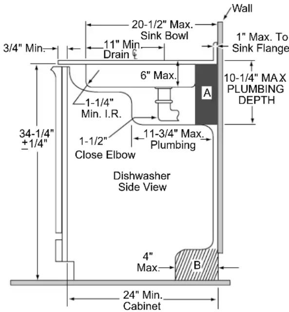
text_image
Wall 20-1/2" Max. Sink Bowl 11" Min. Drain 3/4" Min. 6" Max. 1" Max. To Sink Flange 10-1/4" MAX PLUMBING DEPTH 1-1/4" Min. I.R. A 1-1/2" Close Elbow 11-3/4" Max. Plumbing Dishwasher Side View 34-1/4" +1/4" 4" Max. B 24" Min. Cabinet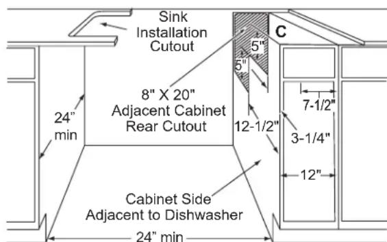
text_image
Sink Installation Cutout 8" X 20" Adjacent Cabinet Rear Cutout C 24" min Cabinet Side Adjacent to Dishwasher 24" min 5" 5" 12-1/2" 7-1/2" 3-1/4" 12"NOTE: A gap between the dishwasher tub front flange and the front of the base cabinet may result due to either the cabinet being less than 24" deep or the sink bowl not being installed to specifications. If the gap is more than 3/4", the sink bowl must be relocated to meet specified dimensions.
① VERIFY OR INSTALL POWER RECEPTACLE
■ If there is an existing grounded receptacle available for the dishwasher, skip to step 2.
⚠ WARNING
RISK OF ELECTRIC SHOCK, FIRE OR INJURY TO PERSONS.
Remove house fuse or turn circuit breaker off before beginning installation of the receptacle.
The receptacle must be properly grounded. Check with a qualified electrician if you are in doubt as to whether the receptacle is properly grounded.

text_image
House Wire Strain Relief Junction Box GFCI/AFCI Receptacle Junction Box Cover■ Install the included GFCI/AFCI receptacle per National Electric Code (NEC) and local codes and ordinances.
■ GFCI/AFCI receptacle must be installed in an adjacent cabinet so that it is readily accessible without the use of tools.
■ GFCI/AFCI receptacle must NOT be installed under a sink.
- Secure the receptacle junction box to cabinetry using appropriate wood screws.
- Secure house wiring to the receptacle junction box with the included strain relief.
■ Enclose receptacle junction box with the included junction box cover.
As an alternate to using the provided electrical receptacle, you can remove the power cord from the dishwasher and hardwire using the Power Cord Conversion Kit PCDPC01KIT.
We recommend having a licensed electrician or qualified technician perform this conversion.
Order on-line at Bodewell.com/parts-search today, 24 hours a day or by phone at 833-4BODEWELL (833-426-3393) during normal business hours. In Canada, visit your local GE Appliances parts distributor, call 800.661.1616 or visit online GEAppliances.ca/en/products/parts-filters-accessories.
② OPTIONAL - REPLACE DECORATIVE TOEKICK WITH STAINLESS STEEL APPEARANCE INCLUDED WITH KIT
■ Skip to step 3 if not replacing the toekick.
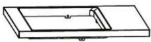
■ Remove the two screws securing the decorative toekick to the dishwasher. Remove toekick.
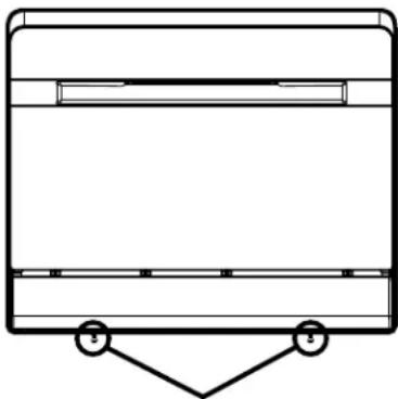
natural_image
Simple line drawing of a rectangular container with a triangular support at the bottom (no text or symbols)Remove toekick screws and decorative toekick
③ INSTALLLEVELER
- Place the leveler rod onto its hub at the rear of the bottom frame.
- Secure the front end of the leveler rod by installing the leveler fastener nut through its hole in the front frame and into the leveler rod. Make sure the wings on the leveler fastener nut spring open to secure the leveler assembly within the frame.
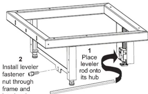
text_image
2 Install leveler fastener nut through frame and into levelers 1 Place leveler rod onto its hubInstallation Instructions
4 PLACE THE DISHWASHER ON THE PLATFORM
■ Carefully lay the dishwasher on one of its sides.
NOTE: Do NOT lay the dishwasher on its back.
■ Attach the platform to the dishwasher bottom using 6 Type A screws.
■ Carefully set the dishwasher and platform assembly upright onto its feet.
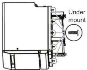
text_image
Under mount⑤ LOOSEN TOP TWO SCREWS
■ Loosen top two screws to allow the toekick panel to slide adjust up and down.
natural_image
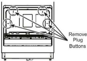
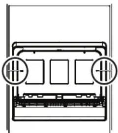
Pure mechanical assembly diagram without any text, numbers, or symbols⑥ REMOVE PLUGS TO PREPARE TO INSTALL FRAME
■ Remove the interior plug buttons and push the rubber plugs from the inside of the tub. Access to these four holes will be needed later in the installation.
text_image
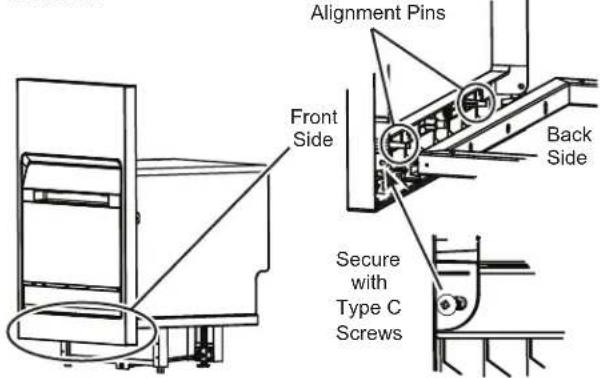
Remove Plug Buttons7 SECURE FRONT FRAME TO THE DISHWASHER
■ Align the holes in the frame with the holes in the platform.
- Secure the frame to the platform using 2 Type C screws.
text_image
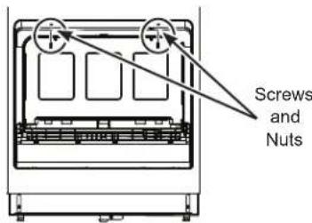
Alignment Pins Front Side Back Side Secure with Type C Screws■ Secure the dishwasher to the frame through the top mounting holes using the 2 Type B screws and nuts.
■ Replace top plug buttons.
text_image
Screws and NutsIMPORTANT: Make sure to securely replace the top plug buttons to ensure a waterproof seal inside the dishwasher.
⑧ PREPARE FOR DRAIN HOSE CONNECTION
■ The molded end of the drain hose will fit 5/8" through 1" diameter inlet ports on the air gap or waste tee.
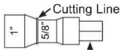
IMPORTANT: Do not cut this portion of hose.
■ Determine size of inlet port. If required, cut drain hose connector on the marked line, to fit the inlet port.
⑨ CONNECT WATER SUPPLY AND DRAIN HOSES TO DISHWASHER
■ Water Supply Hose: If not installed, install rubber washer in one end of water supply hose. Thread the water supply hose onto the inner connector on the rear of the dishwasher. Hand tighten and use pliers to tighten hose between 1/8 and 1/4 turn beyond hand-tight.
- Drain Hose: If not installed, install rubber washer in one end of drain hose. Thread the drain hose onto the outer connector on the rear of the dishwasher. Hand tighten and use pliers to tighten hose between 1/8 and 1/4 turn beyond hand-tight.
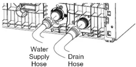
text_image
Water Supply Hose Drain Hose10 CONNECT WATER, DRAIN AND ELECTRIC TO HOUSE CONNECTIONS
■ Connect the water supply and drain hoses to the house connections.
■ Plug power cord into receptacle.
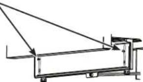
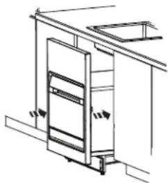
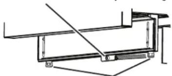
11 PUSH THE DISHWASHER AND FRAME ASSEMBLY INTO THE CABINET
■ Use an adjustable wrench to adjust the front legs. Use an allen wrench in the front center to adjust the back rear legs.
■ Use an adjustable wrench to adjust the bottom frame to the proper height.
natural_image
Technical line drawing of a door mechanism with directional arrows indicating movement (no text or symbols)Use an allen wrench to adjust rear legs
natural_image
Technical line drawing of a structural frame assembly (no text or symbols)Use an adjustable wrench
to adjust front legs
12 SECURE THE TOEKICK
■ Slide the toekick down against the floor and tighten the upper two toekick screws.
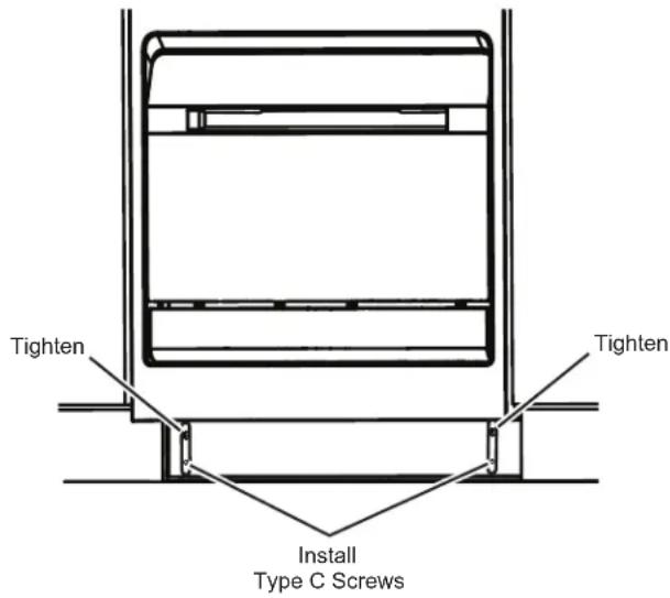
text_image
Tighten Tighten Install Type C Screws- Secure and finish the toekick by installing two Type C screws in its lower corners.
13 ATTACH DISHWASHER TO CABINET SIDES
■ From the inside of the dishwasher, drive 2 Type D screws through the dishwasher and frame to secure it to the side cabinets. NOTE: Drill pilot holes if needed.
■ Replace the side plug buttons.
IMPORTANT: Make sure to securely replace the side plug buttons to ensure a waterproof seal inside the dishwasher.
natural_image
Pure technical line drawing of a mechanical component with no text or symbols
Two Type D Screws
14 TURN ON POWER
■ Turn on power at circuit breaker/fuse box.
natural_image
Line drawing of a handheld electric drill with screwdriver and power plug (no text or symbols)Clé hexagonale M6
□ Pinces
□ Clé ajustable
□ Tournevis cruciforme
□ Crayon
□ Niveau
Ruban à mesurer
▲ AVERTISSEMENT
natural_image
Technical line drawing of a rectangular frame with support legs and mounting feet (no text or symbols)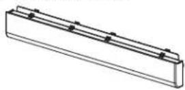
natural_image
Technical line drawing of a rectangular enclosure with mounting holes and a separate view of a rectangular panel (no text or symbols)☐ Prise DDFT/DDAA
□ Serre-câble
Boyau de vidange
▲ AVERTISSEMENT
DIMENSIONS DU PRODUIT
text_image
23-3/4 po 9-3/4 po 17-3/8 po 3-1/4 po 3-1/4 to 4-5/8 po* 1 po 21-3/4 po 1 po 33-1/4" to 34-5/8"*natural_image
Technical line drawing of a mechanical device with no visible text or symbolsPRÉPAREZ LE BOÎTIER DU LAVE-VAISSELLE
▲AVERTISSEMENT
natural_image
Pure technical line drawing of a mechanical assembly without any text, numbers, or symbols⑥ RETIREZ LES BOUCHONS POUR PRÉPARER L'INSTALLATION DU CADRE
natural_image
Technical line drawing of a door frame structure with no visible text or symbols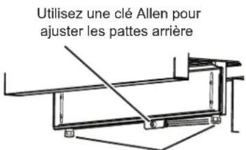
natural_image
Pure technical diagram of a mechanical or electrical component with no text, numbers, or symbols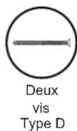
14 METTEZ SOUS TENSION
natural_image
Line drawing of a handheld electric drill with multiple drill bits (no text or symbols)□ Llave Allen M6
Pinzas
□ Llave ajustable
□ Destornillador Phillips
□Lápiz
□ Nivel
Cinta de medición
ADVERTENCIA
natural_image
Technical line drawing of a rectangular frame with supports and mounting feet (no text or symbols)
natural_image
Technical line drawing of a rectangular enclosure with mounting holes and a separate view of a rectangular panel (no text or symbols)DIMENSIONES DEL PRODUCTO
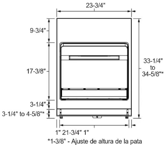
text_image
23-3/4" 9-3/4" 17-3/8" 3-1/4" 3-1/4" to 4-5/8"* 1" 21-3/4" 1" *1-3/8" - Ajuste de altura de la pata 33-1/4" to 34-5/8"*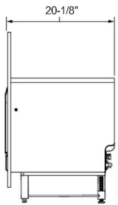
text_image
20-1/8"
natural_image
Technical line drawing of a mechanical device with a vertical panel and base mount (no text or symbols)PREPARE EL GABINETE DEL LAVAVAJILLAS
ADVERTENCIA
GEAppliances.ca/en/products/parts-filters-accessories.