Profile PCDBI01KIT - Dishwasher GE - Free user manual and instructions
Find the device manual for free Profile PCDBI01KIT GE in PDF.

User questions about Profile PCDBI01KIT GE
0 question about this device. Answer the ones you know or ask your own.
Ask a new question about this device
Download the instructions for your Dishwasher in PDF format for free! Find your manual Profile PCDBI01KIT - GE and take your electronic device back in hand. On this page are published all the documents necessary for the use of your device. Profile PCDBI01KIT by GE.
USER MANUAL Profile PCDBI01KIT GE
Installation Instructions
Built-In Kit PCDBI01KITFS
ENGLISH / FRANÇAIS / ESPAÑOL
Questions? Call 833-4BODEWELL (833-426-3393) or visit our Website at: GEAppliances.com In Canada, call 1.800.561.3344 or visit our Website at: GEAppliances.ca
VIDEO
■ Use this video to aid in installing the dishwasher.
NOTE: These installation instructions, including all safety information, should be followed completely.

text_image
QR code image containing encoded data, no visible human-readable textWARNING
Disconnect power before installing. Failure to do so could result in
serious injury or death.
BEFORE YOU BEGIN
Read these instructions completely and carefully.
- IMPORTANT – Save these instructions for local electrical inspector's use.
- IMPORTANT – Observe all governing codes and ordinances.
- IMPORTANT – This kit is intended to be used only with PZF560 Series Profile Compact Dishwashers - See the Owner's Manual for details.
- Note to Installer – Be sure to leave these instructions with the Consumer.
- Note to Consumer – Keep these instructions for future reference.
• Installation must be performed by a qualified installer.
• Proper installation is the responsibility of the installer.
TOOLS YOU WILL NEED
Safety Glasses
□Gloves
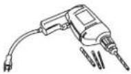
Drill and Bits
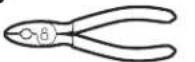
□ Pliers
Phillips Screwdriver
□ Pencil
Level
□ Measuring Tape

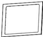
CONTENTS
Frame
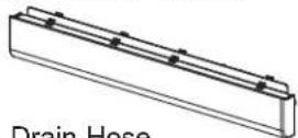
□ Decorative Toekick
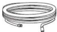
□ Drain Hose
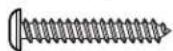
☐ Type A - 1/2" Flat Head Wood Screws (4)

Type B - 1" Machine Screws and Nuts (2)
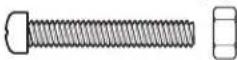
☐ Type C - 1" Black Screws (4)
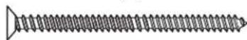
☐ Type D - 2-3/4" Wood Screws (2)
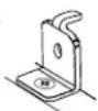
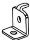
L Bracket (2)
Cover Stickers (2)

NOTE: Parts use will vary depending on installation situation and installation method requirements.
Installation Instructions
WARNING
For your safety, the information in this manual must be followed to minimize the risk of fire, explosion, electric shock, and to prevent property damage, personal injury, or death.
WARNING

- ELECTRICAL SHOCK HAZARD
■ Plug into a grounded 3-prong outlet.
■ DO NOT use an adapter.
■ DO NOT remove ground prong.
■ DO NOT use an extension cord.
Failure to follow these instructions can result in death, fire or electrical shock.
ELECTRICAL REQUIREMENTS
CIRCUIT – Individual, properly polarized and grounded 15 or 20 amp circuit breaker or time-delay fuse.
POWER SUPPLY – 2 wire plus ground, 120 Volt, single phase, 60 Hz, alternating current.
Outlet Receptacle – Properly grounded 3-prong receptacle to be located so the power cord is accessible when the dishwasher is in position. If a 2-prong receptacle is present, it is the owner's responsibility to have a licensed electrician replace it with a properly grounded 3-prong grounding type receptacle.

text_image
Ensure proper ground exists before use.Unit must be electrically grounded in accordance with local codes and ordinances, or in the absence of local codes, with latest edition of the NATIONAL ELECTRICAL CODE, ANSI/NFPA NO. 70 or CANADIAN ELECTRICAL CODE, CSA C22.1. Check with a licensed electrician if you are not sure that the dishwasher is properly grounded.
GROUNDING INSTRUCTIONS
This appliance must be grounded. In the event of malfunction or breakdown, grounding will reduce the risk of electric shock by providing a path of least resistance for electric current. This appliance is equipped with a cord having an equipment-grounding conductor and a grounding plug. The plug must be plugged into an appropriate outlet that is properly installed and grounded in accordance with all local codes and ordinances.
WARNING
Improper connection of the equipment-grounding conductor can result in a risk of electrical shock.
Check with a qualified electrician, or service representative or personnel, if you are in doubt as to
whether the appliance is properly grounded. DO NOT modify the plug on the power supply cord. If it will not fit the outlet, have a proper outlet installed by a qualified electrician.
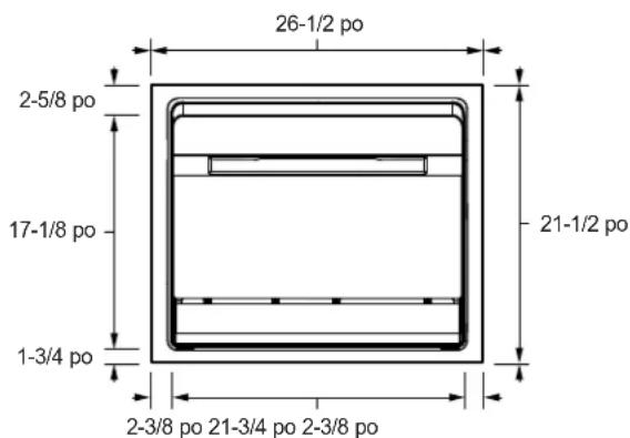
PRODUCT DIMENSIONS
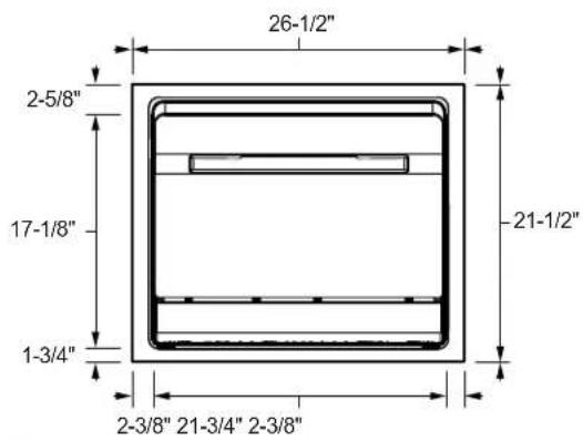
text_image
26-1/2" 2-5/8" 17-1/8" 1-3/4" 21-1/2" 2-3/8" 21-3/4" 2-3/8"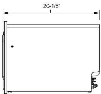
text_image
20-1/8"
natural_image
Line drawing of a rectangular cabinet or enclosure with a side panel and front frame (no text or symbols)IMPORTANT - THERE ARE TWO INSTALLATION METHODS - CHOOSE THE METHOD FOR YOUR INSTALLATION TYPE:
Method A - Installation Directly Below a Countertop Surface - Begin by following the steps immediately below.
OR
Method ☐ - Installation into a Wall Cabinet - Begin on page 6.
Method A - Installation Directly Below a Countertop Surface.
A1 PREPARE THE OPENING
WARNING
To reduce the risk of electric shock, fire, or injury to persons, the installer must ensure that the dishwasher is completely enclosed at the time of installation.
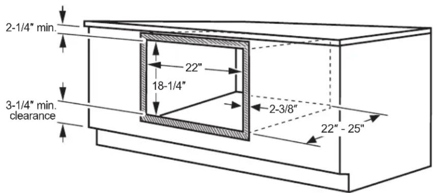
text_image
2-1/4" min. 22" 18-1/4" 3-1/4" min. clearance 2-3/8" 22"-25"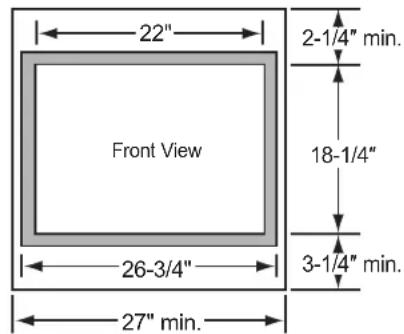
text_image
22" 2-1/4" min. Front View 18-1/4" 3-1/4" min. 26-3/4" 27" min.Base cabinet must be 27" width or greater.
Construct a solid dishwasher floor of 3/8" min. thick plywood supported by 2 x 4 or 2 x 2 runners on all sides.
Must be able to support weight of dishwasher and contents.
Confirm the opening in the cabinet matches the dimensions shown.
■ Frame overlap will conceal cut edges on all sides of the opening. If installing:
-Below a countertop, cabinet door or surface, leave at least 2-1/4" clearance above the opening for trim kit overhang.
- Above a cabinet door or surface, leave at least 3-1/4" clearance below the opening for trim kit overhang and mounting screws.
■ Construct a solid dishwasher floor of 3/8" min. thick plywood supported by 2 x 4 or 2 x 2 runners on all sides.
■ The support must be level and rigidly mounted, flush with the bottom edge of the cutout.
■ Ensure the side walls can support side-mounting the dishwasher; add blocking if needed. See step A7 for details on side mounting.
Cabinet Preparation and Wire Routing
■ The power supply receptacle for the appliance should be installed in a cabinet or on a wall adjacent to the under-sink or built-in space in which the appliance is to be installed.
■ There should be an opening through the partition that is large enough for the attachment plug to pass through. The longest dimension of the opening should not be larger than 1-1/2".
■ The edges of the opening should be smooth and rounded if the partition is wood. If the cabinet wall is metal, the hole must be covered with a bushing. You can find this bushing at your local hardware or home improvement store.
■ Care should be exercised when the appliance is installed or removed, to reduce the likelihood of damage to the power supply cord.
A2 PREPARE FOR DRAIN HOSE CONNECTION
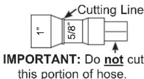
■ The molded end of the drain hose will fit 5/8" through 1" diameter inlet ports on the air gap or waste tee.
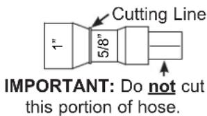
text_image
Cutting Line 1" 5/8" IMPORTANT: Do not cut this portion of hose.■ Determine size of inlet port. If required, cut drain hose connector on the marked line, to fit the inlet port.
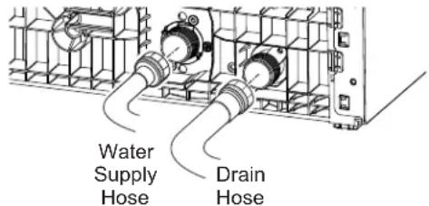
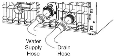
A3 CONNECT WATER SUPPLY AND DRAIN HOSES TO DISHWASHER
■ Water Supply Hose: If not installed, install rubber washer in one end of water supply hose. Thread the water supply hose onto the inner connector on the rear of the dishwasher. Hand tighten and use pliers to tighten hose between 1/8 and 1/4 turn beyond hand-tight.
- Drain Hose: If not installed, install rubber washer in one end of drain hose. Thread the drain hose onto the outer connector on the rear of the dishwasher. Hand tighten and use pliers to tighten hose between 1/8 and 1/4 turn beyond hand-tight.
text_image
Water Supply Hose Drain HoseA4 OPTIONAL - REPLACE DECORATIVE TOEKICK WITH STAINLESS STEEL APPEARANCE INCLUDED WITH KIT
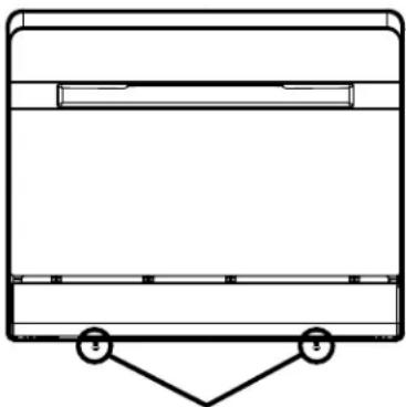
- Skip to step A5 if not replacing the toekick.
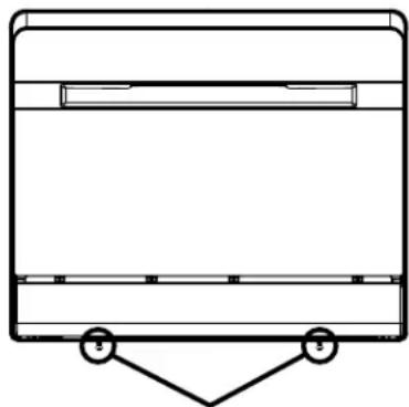
■ Remove the two screws securing the decorative toekick to the dishwasher. Remove toekick.
natural_image
Simple line drawing of a rectangular container with a triangular support at the bottom (no text or symbols)Remove toekick screws and decorative toekick
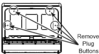
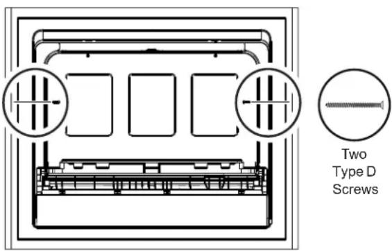
A5 REMOVE PLUGS TO PREPARE TO INSTALL FRAME
■ Remove the interior plug buttons and push the rubber plugs from the inside of the tub. Access to these four holes will be needed later in the installation.
text_image
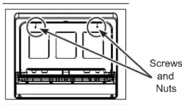
Remove Plug ButtonsA6 SECURE FRONT FRAME TO THE DISHWASHER
■ Secure the dishwasher to the frame through the top mounting holes using the 2 Type B screws and nuts.
■ Replace top plug buttons.
text_image
Screws and NutsIMPORTANT: Make sure to securely replace the top plug buttons to ensure a waterproof seal inside the dishwasher.
A7 PLACE DISHWASHER INTO CABINET AND ATTACH TO CABINET SIDES
■ Pass the power cord, the water hose and the drain hose through their holes in the cabinet wall and place the dishwasher into the cabinet.
■ From the inside of the dishwasher, drive 2 Type D screws through the dishwasher and frame to secure it to the side cabinets. NOTE: Drill pilot holes if needed.
text_image
Two Type D Screws■ Replace the side plug buttons.
IMPORTANT: Make sure to securely replace the side plug buttons to ensure a waterproof seal inside the dishwasher.
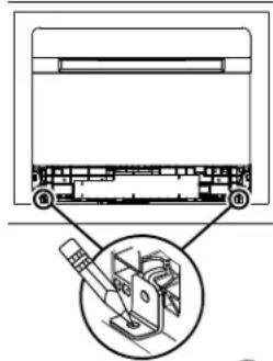
A8 POSITION FRAME ONTO THE CABINET FRONT
■ Position the frame on the cabinet and ensure that the door opens and closes freely.
■ Mark and drill 2 bottom pilot holes.
■ Use 2 Type C screws to attach the bottom of the frame on the cabinet front.
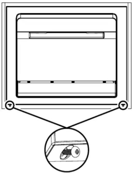
natural_image
Diagram of a cabinet with an inset showing internal components (no text or symbols)A9 CONNECT WATER, DRAIN AND ELECTRIC
■ Connect the water supply and drain hoses to the house connections.
■ Plug power cord into receptacle.
■ Turn on power at circuit breaker/fuse box.
Method B - Installation into a Wall Cabinet.
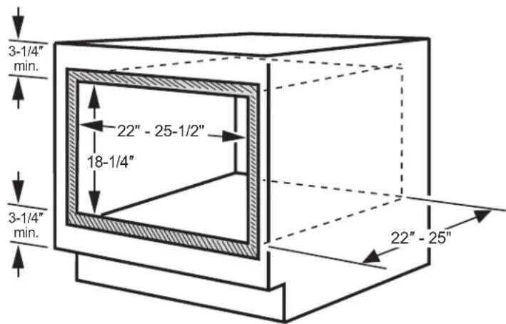
B1 PREPARE THE OPENING
⚠ WARNING
To reduce the risk of electric shock, fire, or injury to persons, the installer must ensure that the dishwasher is completely enclosed at the time of installation.
text_image
3-1/4" min. 22" - 25-1/2" 18-1/4" 3-1/4" min. 22" - 25"Base cabinet must be 27" width or greater.
Construct a solid dishwasher floor of 3/8" min. thick plywood supported by 2 x 4 or 2 x 2 runners on all sides.
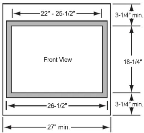
text_image
22" - 25-1/2" 3-1/4" min. Front View 18-1/4" 26-1/2" 3-1/4" min. 27" min.Must be able to support weight of dishwasher and contents.
Cut the opening in a cabinet to the dimensions shown.
■ Frame overlap will conceal cut edges on all sides of the opening.
If installed above or below another cabinet door or surface, allow at least 3-1/4" of clearance above and below the opening. This separation will provide clearance for the trim kit overhang and installation of mounting screws.
■ Construct a solid dishwasher floor of 3/8" min. thick plywood supported by 2 x 4 or 2 x 2 runners on all sides.
■ The support must be level and rigidly mounted, flush with the bottom edge of the cutout.
Cabinet Preparation and Wire Routing
■ The power supply receptacle for the appliance should be installed in a cabinet or on a wall adjacent to the built-in space in which the appliance is to be installed.
■ There should be an opening through the partition that is large enough for the attached plug to pass through. The longest dimension of the opening should not be larger than 1-1/2".
■ The edges of the opening should be smooth and rounded if the partition is wood. If the cabinet wall is metal, the hole must be covered with a bushing. You can find this bushing at your local hardware or home improvement store.
■ Care should be exercised when the appliance is installed or removed, to reduce the likelihood of damage to the power supply cord.
B2 PREPARE FOR DRAIN HOSE CONNECTION
■ The molded end of the drain hose will fit 5/8" through 1" diameter inlet ports on the air gap or waste tee.
text_image
Cutting Line 1" 5/8" IMPORTANT: Do not cut this portion of hose.■ Determine size of inlet port. If required, cut drain hose connector on the marked line, to fit the inlet port.
B3 CONNECT WATER SUPPLY AND DRAIN HOSES TO DISHWASHER
■ Water Supply Hose: If not installed, install rubber washer in one end of water supply hose. Thread the water supply hose onto the inner connector on the rear of the dishwasher. Hand tighten and use pliers to tighten hose between 1/8 and 1/4 turn beyond hand-tight.
- Drain Hose: If not installed, install rubber washer in one end of drain hose. Thread the drain hose onto the outer connector on the rear of the dishwasher. Hand tighten and use pliers to tighten hose between 1/8 and 1/4 turn beyond hand-tight.
text_image
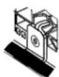
Water Supply Hose Drain HoseB4 REMOVE TOEKICK AND POSITION DISHWASHER IN CABINET
■ Remove the two screws securing the decorative toekick to the dishwasher. Remove toekick.
natural_image
Simple line drawing of a rectangular container with a triangular support at the bottom (no text or symbols)Remove toekick screws and decorative toekick
■ Pass the power cord, the water hose and the drain hose through their holes in the cabinet wall and place the dishwasher into the cabinet.
■ Use the outer frame to properly locate the dishwasher to the desired position and flushness.
B5 INSTALLBRACKETS
■ Remove frame and place mounting brackets in front of the dishwasher in the correct locations. Mark bracket locations and drill pilot holes in the cabinet.
■ Push dishwasher back to allow access to secure the brackets to the cabinet. Install the brackets to the cabinet base using two Type A screws.
■ Pull the dishwasher forward and align its mounting holes with the brackets. Secure the brackets to the dishwasher using two Type A screws.
■ Place a cover sticker or a piece of electrical tape over each bracket.
■ Replace the toekick. You can use either the original black toekick or the silver toekick provided with this Built-In kit. NOTE: Original screws are no longer needed and can be discarded.
natural_image
Technical diagram of a mechanical assembly with a magnified inset showing internal components (no text or labels)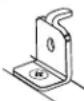

B6 POSITION FRAME ONTO THE CABINET FRONT
■ Position the frame on the cabinet and ensure that the door opens and closes freely.
■ Mark and drill pilot holes.
■ Use 4 Type C screws to attach the frame on the cabinet front.
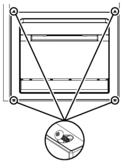
text_image
Diagram showing a mechanical or electrical component with three labeled points and a magnified inset highlighting a component detail.B7 CONNECT WATER, DRAIN AND ELECTRIC
■ Connect the water supply and drain hoses to the house connections.
■ Plug power cord into receptacle.
■ Turn on power at circuit breaker/fuse box.
DIMENSIONS DU PRODUIT
text_image
26-1/2 po 2-5/8 po 17-1/8 po 1-3/4 po 21-1/2 po 2-3/8 po 21-3/4 po 2-3/8 po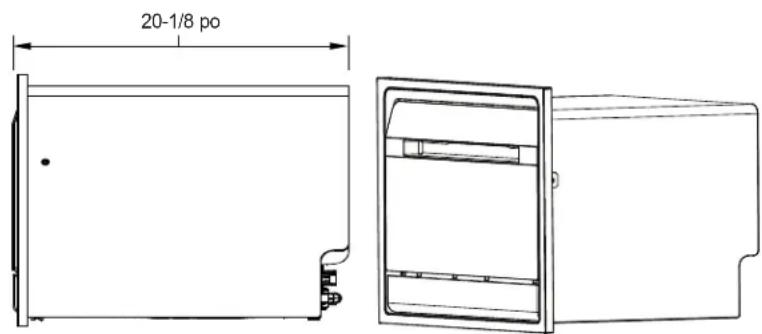
text_image
20-1/8 poIMPORTANT - IL EXISTE DEUX MÉTHODES D'INSTALLATION – CHOISISSEZ LA MÉTHODE ADAPTÉE À VOTRE TYPE D'INSTALLATION :
natural_image
Diagram of a room interior with a ceiling-mounted unit and an inset showing a wall-mounted fixture (no text or symbols)A9 RETIREZ LA PLINTHE ET PLACEZ LE LAVE-VAISSELLE DANS L'ARMOIRE
natural_image
Simple line drawing of a rectangular container with a triangular support at the bottom (no text or symbols)natural_image
Technical diagram of a mechanical assembly with a magnified inset showing internal components (no text or labels)natural_image
Pure diagram of a mechanical assembly with no text, numbers, or symbolsB7 RETIREZ LA PLINTHE ET PLACEZ LE LAVE-VAISSELLE DANS L'ARMOIRE
DIMENSIONES DEL PRODUCTO
26-1/2"
20-1/8"
2-5/8"
17-1/8"
21-1/2"
1-3/4"
2-3/8" 21-3/4" 2-3/8"
Base cabinet must be 27" width or greater.
Construct a solid dishwasher floor of 3/8" min. thick plywood supported by 2 x 4 or 2 x 2 runners on all sides.
Must be able to support weight of dishwasher and contents.
natural_image
Diagram of a ceiling-mounted device with a magnified inset showing internal components (no text or symbols)A9 CONECTARAGUA, DESAGÜEY ELECTRICIDAD
natural_image
Simple line drawing of a rectangular container with two hanging weights at the bottom (no text or symbols)text_image
Technical diagram showing a mechanical assembly with labeled parts and an inset close-up of a device component.