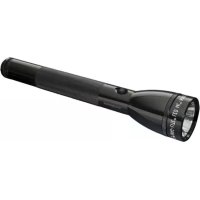
ML150LRX - Flashlight Maglite - Free user manual and instructions
Find the device manual for free ML150LRX Maglite in PDF.


User questions about ML150LRX Maglite
0 question about this device. Answer the ones you know or ask your own.
Ask a new question about this device
Download the instructions for your Flashlight in PDF format for free! Find your manual ML150LRX - Maglite and take your electronic device back in hand. On this page are published all the documents necessary for the use of your device. ML150LRX by Maglite.
USER MANUAL ML150LRX Maglite
©2022 Mag Instrument, Inc.
www.maglite.com
421-000-973 1/22

MAGLITE ^® ML150LR ^TM /ML150LRS ^TM
THE PROFESSIONAL FLASHLIGHT®
LED Rechargeable Flashlight System
LED oplaadbaar zaklampsysteem
For Your Safety Please Read
Read all safety instructions in this manual before attempting to use the ML150LR™/ML150LRS™ LED Rechargeable Flashlight System. Keep this manual for future reference. It contains important information about safe operation and maintenance of the product.
SAFETY INSTRUCTIONS:
The safety instructions in this manual have been classified according to the seriousness of the risk, as follows:
⚠ WARNING:
"Warning" indicates a hazardous situation that, if not avoided, could result in death or serious injury.
CAUTION:
"Caution" indicates a hazardous situation that, if not avoided, could result in minor or moderate injury.
△NOTICE:
"Notice" indicates information considered important that relates to avoiding risk of damage to the flashlight or flashlight system itself and/or to other property.
⚠️WARNINGS:
- The ML150LRTM/ML150LRS™ flashlight is a high-intensity lighting device that is safe during normal operating use in which it is used to project light at a distance and the lens is not obstructed or blocked. It is not intended for use in hazardous environments, such as explosive environments, where only devices with appropriate hazardous certifications (such as "intrinsically safe" and/or "explosion-proof") should be used. If the device is left on when the lens is obstructed or blocked, such misuse may create a potentially dangerous heat build-up, which could possibly result in fire, depending upon the environment in which the device is being misused.
- This flashlight is a high-intensity lighting device capable of causing eye damage to the user or others. Avoid shining the flashlight directly into anyone's eyes.
- As is the case with any battery, never allow it to short circuit and do not expose the battery of this device to fire or excessive heat, as this could cause the battery to leak, rupture or explode.
- The charging cradle is not waterproof and should only be used in dry indoor locations. Exposing the device's charging system to liquids could cause shorting and possible fire and/or electric shock.
- Never try to disassemble, repair or alter the AC adapter, plug or charging cradle. Shorting and possible fire and/or electric shock could result. Contact a Mag Authorized Warranty Service Center for repairs.
CAUTION:
- The flashlight is not designed to operate with the face cap off and the LED exposed. If contacted directly, the exposed LED could become hot enough to burn skin, or to melt or scorch some heat-sensitive materials, e.g., plastics, rubber, cloth fabrics, etc.
- Any battery may leak harmful chemicals which may damage eyes, skin, clothing, or the inside of the flashlight. To avoid risk of injury, never disassemble a battery pack, and do not let any material leaked from a battery come in contact with eyes or skin. In the event of contact with eyes or skin, wash the affected area immediately and obtain prompt medical attention.
△NOTICE:
To reduce the risk of harm to your flashlight:
- Locate power cord away from foot traffic and other causes of abrasion or stress.
- Never pull on the power cord when unplugging the AC adapter. Grasp the plug directly.
- Do not use non-rechargeable batteries in your Rechargeable Flashlight System. Use only a MAG ^ rechargeable battery pack (ML150LRTM Model No. 485-000-034), (ML150LRS ^TM Model No. 485-000-075).
- For prolonged storage, remove the battery pack and store it separately in a non-conductive wrapping, such as a plastic bag.
- Carefully follow steps listed under "Inspection and Maintenance" in this manual.
- Always use genuine ML150LRTM/ML150LRS™ replacement parts and accessories. Never connect the flashlight to any auxiliary product that has not been approved by Mag Instrument, Inc. Doing so may damage the product and void your warranty.
- Discontinue use immediately if you notice changes in the battery such as swelling, discoloration or leakage.
- Recharge the Battery at temperatures between 32^ and 140^ (0°C to 60°C), as charging outside this range can potentially reduce battery capacity.
PROTECTION OF CHILDREN
• This product is not a toy, and is not intended or recommended for use by children.
- Keep the flashlight, all accessories and components out of the reach of small children – especially small parts that might present a choking hazard to children.
BATTERY DISPOSAL
- Cover the metal terminals with insulating tape before disposal, to prevent accidental short-circuiting.
-
Never dispose of a battery pack by throwing it into a fire. Battery explosion could result.
-
Never discard a used battery pack with ordinary solid wastes, since it contains toxic substances.
- The sealed Lithium Iron Phosphate (LiFePO_4) battery stick supplied with your flashlight must be recycled or disposed of properly. Contact your local solid waste authority for proper recycling or disposal information.
Mag Instrument, Inc. is a proud participant in the RBRC (Rechargeable Battery Recycling Corporation). By recycling LiFePO_4 rechargeable batteries, you are helping to keep LiFePO_4 batteries out of the solid waste stream. When you throw away a LiFePO_4 battery, it eventually ends up in a landfill or municipal incinerator. By recycling your used LiFePO_4 batteries through Mag Instrument's Battery Recycling Program, you are helping to create a cleaner and safer environment for generations to come. For more information about the RBRC visit www.rbrc.com

www.maglite.com
MAGLITE ML150LR/ML150LRS LED Rechargeable Flashlight System
Contents
Getting Started 4
The Flashlight.... 5
The Charging Cradle....6
Installation....7
Battery/Battery Charging....8
Operation - Getting the Most out of
Your ML150LR™/ML150LRS™ LED
Rechargeable Flashlight System....10
Frequently Asked Questions 11
Troubleshooting, Specifications..... 12
Inspection and Maintenance .... 12
Warranty....13
Nederlands 14
Français.... 26
Deutsch 38
Italia 50
Español 62

Getting Started
Taking a few moments to read this manual and familiarizing yourself with the ML150LRTM/ML150LRSTM LED Rechargeable Flashlight System will help to insure years of superior service and satisfaction.
Not all of the following 8 Items are included with every Rechargeable Flashlight System shipped, as some package contents may vary. To confirm which of the 8 items are included with your System, consult the package in which the System was sold.
-
Flashlight
-
120 Volt Converter (US)
-
240 Volt Converter (UK)
-
Charging Cradle
-
12 Volt Adapter (Automobile)
8.12 Volt Straight Wire
-
Rechargeable Battery (LiFePO4)
-
230 Volt Converter (Euro)
(Automobile)

natural_image
Collection of electronic devices including a flashlight, battery pack, charging plug, and cord (no visible text or labels)This manual covers both ML150LR™ & ML150LRS™ flashlights. Images shown are the ML150LR™.
Section 1
The Flashlight
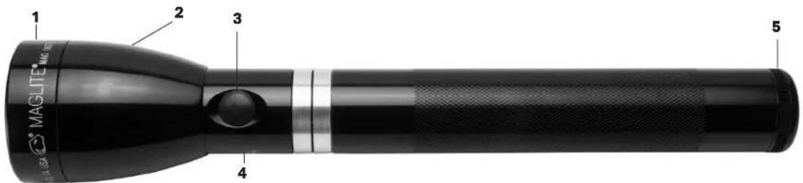
text_image
1 2 3 4 5 MAGLITE® 7.5X US-
Face Cap - The removable face cap, which is threaded onto the head, is O-ring sealed and retains the polycarbonate lens and the precision-engineered reflector that is the heart of the optical system.
-
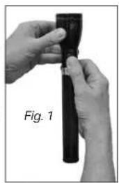
Head - The head houses the reflector and the LED module. The flashlight's Quick-Adjustable Beam operates by rotating the head. About 14 turn of the head causes the beam to vary between a wide floodlight setting and a narrow spotlight setting (Fig. 1). To remove the head, first remove the face cap and reflector; the head is then free to slide down the barrel. This maneuver provides access to the O-ring seal that is seated in a groove on the outside of the barrel, near the head end, and seals the head-barrel assembly against grit and moisture.
natural_image
Close-up of hands holding a black cylindrical object, labeled 'Fig. 1' (no other text or symbols visible)-
Switch - Sealed, flush-with-the-barrel electronic switch provides access to five different functions - Full Power, Low Power, Strobe (12x/sec), Eco, and Momentary On/Off.
-
Serial Number - Your flashlight's unique serial number is permanently engraved on the barrel for ease of identification and registration. Please note your serial number for future reference: ____.
-
Tail Cap - The tail cap is threaded onto the barrel and retains the Lithium Iron Phosphate (LiFePO _4 ) rechargeable battery. The tail cap/barrel junction is sealed by a lip seal that prevents entry of moisture and grit, while allowing the venting of any gas that may be generated within the flashlight. The tail cap can be removed to inspect/replace the battery and to maintain/replace the lip seal.
Section 2
The Charging Cradle
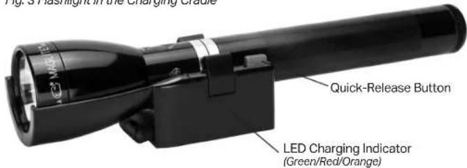
Constructed of engineering grade thermoplastics, this Charging Cradle unit has many features. Input can be from 12–14 volts (automotive installations) or 120-240 volts AC, when used with a converter for charging indoors.
Fig. 3 Flashlight in the Charging Cradle
text_image
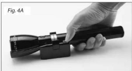
Fig. 3 Flashlight in the Charging Crude Quick-Release Button LED Charging Indicator (Green/Red/Orange)To remove the flashlight from the charging cradle: Grasp the flashlight, press the quick-release button (Fig. 4A) and lift up (Fig. 4B).
To return the flashlight to the charging cradle: Place the front end of the light into the front end of Charging Cradle, lower the flashlight until it clicks into place (Fig. 5).
Once it is mounted to a wall or in a vehicle, you'll find that the technique for removing and returning the flashlight to the Charging Cradle works with one motion.
The quick-release button requires very little force to remove and return the flashlight to the charging cradle.
natural_image
Hand holding a black handheld device labeled Fig. 4A, with no visible text or symbols on the device itself.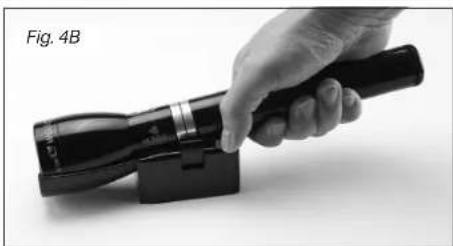
natural_image
Hand holding a black handheld device with a black handle, labeled 'Fig. 4B' (no other text or symbols visible)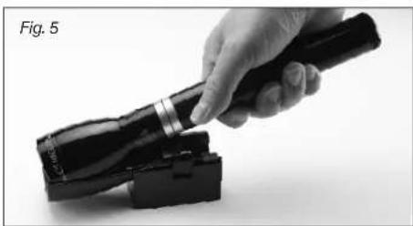
natural_image
Hand holding a flashlight with a black device attached, labeled 'Fig. 5' (no other text or symbols visible)Section 3
Installation
A Typical Installation
-
Locate and mount the cradle using appropriate screws and anchors for the location and material.
-
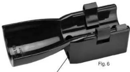
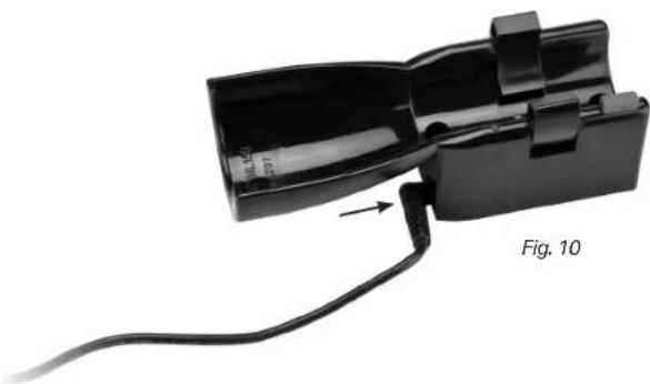
Attach end of DC power cord or AC converter to charging cradle by inserting round plug into power connection port in the side of the charging cradle (Fig. 6, 7 & 10).
⚠ NOTICE: Never pull on the power cord when unplugging the AC adapter. Grasp the plug directly.
FCAUTION: Make sure cable cannot be pinched. If cable is pinched it can cause immediate short and wires can get hot, melt plastic, and create a fire hazard.
natural_image
Black plastic mechanical component with a labeled section 'Fig. 6' (no other text or symbols visible)Power connection port
Direct Wire-Vehicle Installation 12-14 Volt Only (Not for 24-Volt Systems)
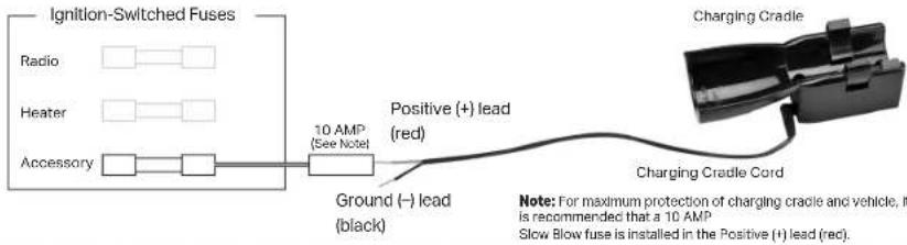
A 6' power accessory cord is available to facilitate the direct-wiring of the rechargeable system (Fig. 7). MAG Instrument recommends using an ignition-switched circuit (fused for 10 or 15 AMPS). This is most often the radio or accessory fuse. The Positive (+) lead (red) is connected to the fuse output, and the Ground (-) lead (black) wire should be attached to a metal part of the chassis, which serves as a battery ground return.
text_image
Ignition-Switched Fuses Radio Heater Accessory 10 AMP (See Note) Positive (+) lead (red) Ground (-) lead (black) Charging Cradle Charging Cradle Cord Note: For maximum protection of charging cradle and vehicle, it is recommended that a 10 AMP Slow Blow fuse is installed in the Positive (+) lead (rec).Section 4
Battery
Your Battery's First Charge Is Important!
To assure the freshness of your battery and to avoid any operational problems in shipping, it has been packaged in an UNCHARGED state.
For optimum operation of your flashlight, it should be charged a full 6 hours ... before using for the first time.
Battery Installation
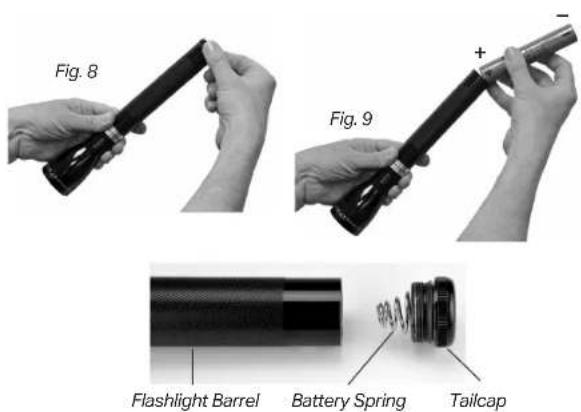
If the battery was shipped outside of the flashlight: After you have removed the flashlight from the Charging Cradle unscrew the tail cap (Fig. 8) and insert battery pack (Fig. 9) into the barrel. The positive (+) end—this is the end with a button—goes into the barrel first. Now screw on the tail cap and make sure it's tight.
NOTE: Large end of the battery spring must be snapped into the tailcap.
text_image
Fig. 8 Fig. 9 Flashlight Barrel Battery Spring TailcapFirst Charge Procedure
- Connect charging cradle to the AC converter or DC accessory cord (Fig. 10).
- Plug into wall receptacle (AC) or DC power source cord.
- Make sure charging cradle indicator LED is GREEN (see next page for explanation of LED indicator colors).
- Make sure flashlight tailcap is tight.
- Place flashlight into charging cradle.
WARNING: As is the case with any battery, never allow it to short circuit and do not expose the battery of this device to fire or excessive heat, as this could cause the battery to leak, rupture or explode.
⚠ NOTICE: For prolonged storage, remove the battery pack and store it separately in a non-conductive wrapping, such as a plastic bag. Cover the metal terminals with insulating tape before disposal, to prevent accidental short-circuiting.
natural_image
Close-up of a black plastic electrical connector with a cable, labeled Fig. 10 (no text or symbols on the component itself)Section 4
Battery Charging
After the first (6-hour) charge, the total time to fully charge a fully discharged battery is approximately (ML150LR™-2.5 hours) (ML150LRS™-1.5 hours).
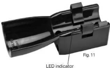
The charging cradle is provided with an LED that indicates battery charge status by blinking and changing color (Fig. 11), as seen in the accompanying chart.
Charger Mode Definitions:
- Charging: Battery charge level is below 80% and will fast charge for up to 6 hours (maximum charge time for a deeply discharged battery). Typical charge time is (ML150LR™-2.5 hours) (ML150LRS™-1.5 hours).
- Top Off/Maintenance: Battery charge level is at (or above) 80% and will be slow charged to top off
- Idle: Battery charge level is at 100% and charging has stopped or there is no light in the cradle
- Fault: Charger input/output Voltage is below the minimum threshold for normal operation, a short-circuit is detected, or a component failure has occurred.
| ML150LRTM/ML150LRSTM - CHARGING CRADLE FUNCTIONS | ||
| Battery State Charger Mode LED Indicator | ||
| 0 - 80% Charging Orange | ||
| > 80% Top Off/Maintenance Blinking | Green | |
| 100% - No Light Idle Green | ||
| Unknown Fault Blinking Red | ||
text_image
LED indicator Fig. 11Switch Operation
Your Flashlight's Function Sets and the Functions Within Each Set
The ML150LRTM/ML150LRS™ LED flashlight includes powerful new electronics, providing five different functions to choose from. Because not all functions are equally important to all users, the ML150LRTM/ML150LRS™ LED flashlight offers an array of USER-CONFIGURABLE FUNCTION SETS that LET YOU PERSONALIZE the settings for QUICKEST ACCESS to the FUNCTIONS YOU USE MOST. The four available Function Sets are shown in the below Function Sets Chart.
Function Sets Chart
| Function Set |  1 GENERAL(Default) 1 GENERAL(Default) |  2 OUTDOOR 2 OUTDOOR |  3 LAWENFORCEMENT 3 LAWENFORCEMENT |  4 TACTICAL 4 TACTICAL |
| Full Power | Full Power | Momentary | Momentary | |
| 3 CLICKS 2 CLICKS | Low Power | Low Power | Full Power | Full Power |
| Eco | Strobe | Eco | Strobe |
The five different functions are: – Full Power, Low Power, Strobe (flashes 12 times per second), Eco and Momentary On/Off (stays on only while the switch button is held down). Not all of these functions are equally important to every user. That is why these functions are organized into four different function sets – so that you can personalize your flashlight to suit your needs, configuring it for quickest access to the functions that best match your preference.
How To Choose A Function Within a Set - "Quick Click"
The available function sets, and the functions within each one, are shown in the Function Sets Chart.
As it comes out of the package, your ML150LR™/ML150LRS™ LED flashlight is set to the "General (Default)" function set (Function Set #1 in the chart). If you require only those three functions (Full Power, Low Power and Eco), then you never have to change it. You can select a function within that set by the "Quick Click" method: Turn the flashlight on with one Quick Click and it is on at Full Power. Turn it off, then turn it on with two Quick Clicks (about as fast as you would say "Click Click") and it turns on at the Low Power function. Turn it off, then turn it on with three Quick Clicks (about as fast as you would say "Click Click Click") and you have the Eco function.
Selecting a function within any of the other function sets works the same way – starting with the flashlight off, invoke the desired function by applying 1, 2 or 3 "Quick Clicks", as the chart shows. For example, if you are in "Outdoor" function set (Function Set #2) and you want to select the Strobe function, begin with the flashlight off, apply three Quick Clicks, and your flashlight will strobe.
How To Go From One Function Set To Another
Your ML150LR™/ML150LRS™ LED flashlight's "General (Default)" setting is Function Set #1. If you want to keep that setting you don't have to do anything. Function Set #1 will always be in effect unless it is changed. If you want to choose a different function set, follow these steps:
Section 5
Operation - Getting the most out of Your ML150LR™/ML150LRS™ LED Rechargeable Flashlight System
METHOD 1
-
Unscrew the tail cap, backing it out of the barrel far enough that the flashlight will not turn on. (Note: This may require the tailcap to be removed from the barrel entirely).
-
Pause for 2 seconds.
-
Press the switch button and keep holding it down.
-
While still holding down the switch button, screw the tail cap back in until it is tight.
-
Keep holding down the switch button. Within about 4 seconds the flashlight will start to blink.
-
The number of blinks indicates the new selected Function Set.
-
To choose a new Function Set, release the switch button after the corresponding number of blinks (releasing after 1 blink chooses Function Set #1; releasing after 2 blinks chooses Function Set #2; release after 3 blinks for Function Set #3, and release after 4 blinks to choose Function Set #4.) Your choice of a Function Set remains in effect until you change it by repeating the above process. (See our Demo video at www.maglite.com)
METHOD 2 - STEP 1
- Click the light into HIGH mode and hold the button down for five seconds. NOTE: If the light is currently configured for Function Set 1 or 2, then the user will begin from the OFF mode, click once and hold.
If the light is currently configured for Function Set 3 or 4, then the user will begin from OFF mode, click twice and hold.
- After five seconds, the light will turn off for .25 seconds and then back on again indicating that the light is now unlocked. The Function Set can be changed at turn-off and without loosening the tail cap (traditional method). - Release the button at any time.
STEP 2
- Click and hold the button down for five seconds.
• After five seconds the light will turn OFF, continue holding the button.
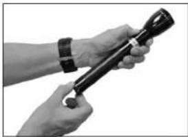
• After three seconds the light will begin to blink in successive patterns which represent a particular Function Set, from this point everything is the same as the traditional method.
NOTE: One blink, is Function Set 1 (GENERAL), release the button to save this set into memory.
natural_image
Close-up of hands holding a flashlight (no visible text or symbols)Two blinks, Function Set 2 (OUTDOOR), release the button to save this set into memory.
Three blinks, Function Set 3 (LAW ENFORCEMENT), release the button to save this set into memory.
Four blinks, Function Set 4 (TACTICAL), release the button to save this set into memory.
⚠NOTICE: To avoid deeply discharging the rechargeable LiFePO₄ battery, always turn the flashlight off when the flashlight beam starts to dim. A dim beam is an indication that the battery needs to be recharged.
Spot-to-Flood Beam
The quick focusing spot-to-flood beam operates with a simple quarter turn of the flashlight head assembly.
Frequently Asked Questions
Q. How long can I leave the flashlight in the Charging Cradle (on charge) without using?
A. Indefinitely. Your charging cradle is suitable for permanent stowage of the flashlight. Because the cradle automatically shuts off when it detects that the flashlight has taken a full charge, you don't ever have to worry about overcharging the flashlight. If the flashlight sits idle in the cradle for a long enough time to lose a little of its charge, the cradle detects that, too, and applies a "top off/maintenance" charge. But again, it will stop charging when the charge is back up to 100%. The cradle will never overcharge the flashlight.
Q. If dust occurs inside my reflector, how do I clean it without damage to the reflector?
A. Do not touch reflector. Use a camel hair brush lightly or blow with a compressed air duster as used on computers and electronics. Use the same care that you would give a precision camera lens.
Q. How do I get a fingerprint off my reflector?
A. Use a camera lens cleaner and a lint-free cloth.
If you have questions or need assistance, please call our warranty/repair facility at 01 (909) 947-1006.
Problem
Cause/Correction
Flashlight: sure battery is installed, with positive (+) end toward head of Does not light.
bus not light hashing
-
Make sure large end of battery spring is snapped into tailcap.
-
Tighten tail can - make sure unplated area of tail can and barrel are
clean. See fig. 12
Battery battery charge: Place flashlight in recharger/cradle. Make
sure LED lights up (see page 8). Charge for 15 minutes ... check
for light. If it lights (even momentarily) charge it, if not replace it
(battery).
Switch sticks 1.
Return flashlight to Mag Instrument (see warranty).
Workside or damage to battery casing.
- Foreign particles inside barrel.
Polo Damnageptled.
Rechlagter/Cribide:
LED indicator connection to
not lightverter
- Check plug to power
2014.03.20
source.
- Make sure large end of
battery spring is
snapped into tailcap.

text_image
Fig. 12 Unplanted AreaInspection and Maintenance
Battery Pack - See Warnings Section for more information. Periodically (approximately every month) remove the battery pack from the flashlight and visually inspect for signs of gas or chemical leakage. Indications of leakage are discoloration of the plastic sleeve or white fuzzy material near the top (positive button) of each cell. Another indication would be a bulging deformation of the bottom (negative flat end) of the cell can. If these signs are observed the battery pack should be removed from service to prevent chemical damage to the inside of the flashlight. See One Year Battery Pack Warranty for more information concerning warranty coverage.
Fully Charged Battery Storage – If you do not use your flashlight for long periods of time (four months or more) we suggest you remove the battery pack from the flashlight to prevent chemical damage (acid leaks). Electrical Contacts – The bare (bright) metal
Flashlight
• Tempered aluminum alloy body
- Finish hard, type III, aircraft anodized (inside and cut)
• Length: ML150LR ^TH -10-11/16'
(271.45 mm) / ML150LRS™-8-174
(210 mm)
1210 mm
• Weight, with battery pack:
ML150LR™-15.5 oz. (439 grams) /
M 150L PS ^TM -11.2 oz (317.51 orame)
METSOLERS 112 62 (517.5 glnk
• Head diameter: 1-15/16" (49.12 mm)
• Barrel diameter: 1-3/16" |30.15 mm
• Permanently engraved serial number
for registration and identification
• O-ring sealed throughout
• 6.4V-ML150LR™ / 3.2V-ML150LRS™
Lithium irin phosphates (FePO _4 )
NaOH from phosphatase (LP)
rechargeable battery pack
• Polycarbonate Lens
• Micro-polished reflector
• Diamond kruvi dojan
Diamond khan design
• Adjustable beam from spot to flood
with about 1/4 turn of head
• Concelon-resistant metal
Corrobion Resistant
springs throughout
Charging Cradle
- Acropis 12-14 volts DC inot for use
Accepts 12-4 volts with 24-volt systems
• Solid-state charging circuit
• Charge rate: 2500 mA
- Reverse voltage protected (prevents
damage if battery is inserted
backwards
• Multi-color LED charge indicator
•
Converter
• 120-240 volts AC 50/60Hz
- Output 13 volts DC
• Double insulated
surfaces between the tailcap and barrel must be cleaned periodically to ensure a good electrical contact. Also keep the tailcap spring clean. O-ring Seals and Screw Threads – To keep seals from drying out and the threads operating smoothly, apply several drops of clean petroleum oil or jelly to these surfaces two or three times a year. Anodized Exterior Finish – The protective finish on the flashlight is very durable; however, constant exposure to sunlight, water, chemicals, gases, etc., will dull, discolor and eventually destroy the protective finish. Care should be taken to avoid any harsh environment.
12 Volt Adapter (Automobile)
Plug the DC power cord's adapter into the 12-14 volt cigarette lighter receptacle of the vehicle. DO NOT leave adapter plugged in for any extended period while the engine is "off" to avoid draining vehicle battery.
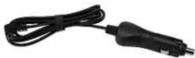
WARNING: This adapter is designed for 12-14 volt systems only. Do not use it to connect to a 24 volt circuit, as doing so can create excessive heat, possibly cause a fire, and damage electrical components.
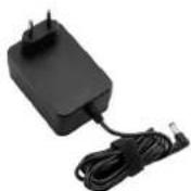
120-240 Volt Converter (Indoor)
After mounting the charging cradle in a proper location, plug the converter into an appropriate 120-240 volt wall receptacle.
Note: Total usable wire length is 6 feet.
TEN YEAR LIMITED WARRANTY ON FLASHLIGHT SYSTEM / ONE YEAR LIMITED WARRANTY ON BATTERY PACK
MAG INSTRUMENT, INC. ("Mag") warrants to the original owner that this ML150LR™/ML150LRTM SYSTEM (the "SYSTEM") is free from defects in parts and workmanship. As to the flashlight and other components of the SYSTEM, except the rechargeable battery supplied herewith, this warranty lasts for ten years from the date of first retail purchase. As to the battery, this warranty lasts for one year from date of purchase. Registration is not required for warranty coverage. Mag or an authorized Mag Warranty Service Center will repair the flashlight or other SYSTEM component or, at its option, replace a defective flashlight or other SYSTEM component free of charge. This warranty is in lieu of all other warranties and conditions, express or implied.
Exclusions: This warranty does not cover LED burnout and/or LED module failure or damage to or failure of the SYSTEM or any component thereof due to alteration, product misuse, lack of maintenance, or leakage of a battery more than one year after date of purchase. (Product misuse includes, but is not limited to, installing any non-rechargeable battery or any rechargeable battery pack other than a Mag® battery pack or its technical equivalent.)
Mag disclaims any responsibility for incidental or consequential damages. Some jurisdictions in do not allow exclusion or limitation of implied warranties, incidental or consequential damages and/or limitations on transferability, so the above limitations and exclusions may not apply to you. THIS WARRANTY DOES NOT AFFECT THE STATUTORY RIGHTS OF A CONSUMER.
How and when to make a warranty claim: Before returning the flashlight or other SYSTEM component for service, be sure you have followed the steps outlined in the Troubleshooting Guide section of your ML150LRTM/ML150LRSTM SYSTEM Owner's Manual. If you have followed all of these steps and the flashlight or other SYSTEM component fails to operate properly, proceed as follows: 1. In case of rechargeable battery failure more than one year after purchase date, do not return the flashlight or other system component to Mag but replace battery. You can buy replacement batteries directly from Mag or from most retail outlets where Mag flashlights are sold. 2. For warranty returns: Send the flashlight or other SYSTEM component (postage or shipping prepaid) to Mag Instrument, 2001 South Hellman Avenue - 50600, Ontario, California, USA 91761-8019, Attention: Warranty/Repair Department, or to an authorized Mag Warranty Service Center. For the location of an authorized Mag Warranty Service Center in your area, consult the retailer where you purchased the flashlight. For your protection and to expedite handling and/or postal claims, we recommend that all returns be insured and sent Certified and/or Return Receipt Requested.
This warranty gives you specific legal rights, and you may have other rights which vary from country to country, state to state and from province to province. Where any term of this warranty is prohibited by the law of any jurisdiction, such term shall there be null and void, but the remainder of this warranty shall remain in full force and effect. To register your new Mag® flashlight visit our website at www.maglite.com. From our home page just go to "Register Your Flashlight." Registration is not required for warranty coverage.
MAGLITE'ML150LR/ML150LRS
LED oplaadbaar zaklampsysteem
Inhoud
Om te beginnen.... 16
De zaklamp 17
De oplaadhouder 18
Installatie 19
Batterij/Batterij laden....20
Rechargeable Flashlight System....22
natural_image
Collection of eight electronic devices and accessories including a flashlight, batteries, and chargers (no visible text or labels)natural_image
Close-up of hands holding a black cylindrical object, labeled 'Afb. 1' (no other text or symbols visible)natural_image
Hand holding a flashlight with a black handle, labeled 'Afb. 4A' in the top-left corner (no other text or symbols visible)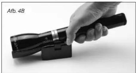
natural_image
Hand holding a flashlight with a black handle, no visible text or symbols on the device itself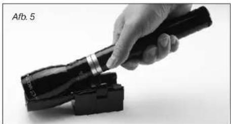
natural_image
Hand holding a flashlight next to a black device (no visible text or symbols)Deel 3
Installatie
natural_image
Close-up of a black plastic mechanical component with cutouts and mounting brackets (no visible text or symbols)natural_image
Close-up of a black plastic electronic device with a cable and labeled component 'Afb. 10' (no readable text beyond label)Batterij laden
natural_image
Close-up of hands holding a black handheld device (no visible text or symbols)METHODE 2 - STAP 1
natural_image
Electric vehicle charging plug and cable (no visible text or symbols)TI ÅRS BEGRÄNSET GARANTI PÅ STAVLYGTESYSTEM/ET ÅRS BEGRÄNSET GARANTI PÅ BATTERIPAKKE
MAGLITE ML150LR/ML150LRS
natural_image
Collection of eight electronic devices and accessories including a flashlight, batteries, and chargers (no visible text or labels)natural_image
Close-up of hands holding a black cylindrical object, labeled 'Fig. 1' (no other text or symbols visible)natural_image
Hand holding a flashlight with a black handle, labeled Fig. 4A (no text on device or background)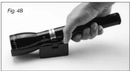
natural_image
Hand holding a black handheld device with a black handle, labeled 'Fig. 4B' (no other text or symbols visible)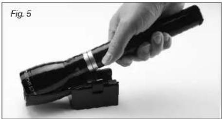
natural_image
Hand holding a flashlight next to a device with a black handle (no visible text or symbols)Section 3
Installation
natural_image
Black plastic mechanical component with internal structure, labeled Fig. 6 (no text or symbols on the component itself)Port d'alimentation
natural_image
Close-up of a black plastic electronic device with a cable and labeled component 'Fig. 10' (no readable text or symbols beyond label)Section 4
Batterie en charge
natural_image
Close-up of hands holding a black handheld device (no visible text or symbols)batterle rechargeable lithium ter
phosphate (LFePO4)
• Lentile en polycarbonate
natural_image
Black and white photo of a connected electrical adapter with two cables (no visible text or symbols)Section 7
MAGLITE ML150LR/ML150LRS
natural_image
Collection of eight electronic devices and accessories including a flashlight, batteries, and chargers (no visible text or labels)natural_image
Close-up of hands adjusting a black cylindrical object, labeled 'Abb. 1' (no other text or symbols visible)natural_image
Hand holding a flashlight with a black handle, labeled Abb. 4A (no other text or symbols visible)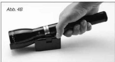
natural_image
Hand holding a black handheld device with a black handle, labeled 'Abb. 4B' (no other text or symbols visible)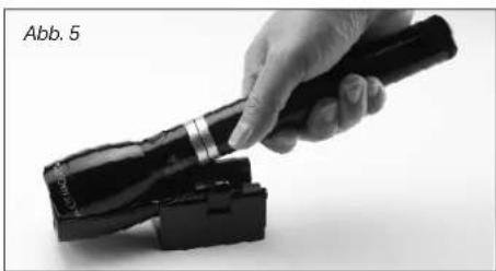
natural_image
Hand holding a flashlight on a black device (no visible text or symbols)natural_image
Close-up of a black plastic electronic component with a cable, labeled 'Abb. 10' (no other text or symbols visible)Abschnitt 4
Batterieaufladung
METHODE 2 - SCHRITT 1
natural_image
Close-up of hands holding a flashlight (no visible text or symbols)mm)/ML150LRS™-8-1/4" (210 mm
MAGLITE ML150LR/ML150LRS
Rechargeable Flashlight System 58
Domande comuni 59
natural_image
Collection of electronic devices including a flashlight, battery pack, charging plug, and cord (no visible text or labels)natural_image
Close-up of hands holding a black cylindrical object, labeled 'Figura 1' (no other text or symbols visible)natural_image
Hand holding a flashlight with a black handle, labeled 'Figura 4A' (no other text or symbols visible)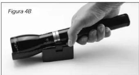
natural_image
Hand holding a black handheld device with a black handle, labeled 'Figura 4B' (no other text or symbols visible)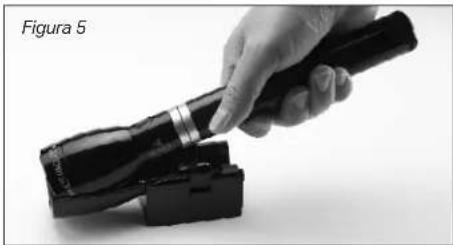
natural_image
Hand holding a flashlight with a black device attached, labeled 'Figura 5' (no other text or symbols visible)Sezione 3
Installazione
natural_image
Black plastic mechanical component with mounting holes and a labeled section (Figura 6), no readable text or symbols on the object itself.natural_image
Close-up of a black plastic device with a cable and connector, labeled 'Figura 10' (no other text or symbols visible)Sezione 4
natural_image
Close-up of hands holding a flashlight (no visible text or symbols)natural_image
Electric charger with attached cable and plug, no visible text or symbols on the device bodyGARANZIA LIMITATA DI DIECI ANNI PER IL SISTEMA DI LAMPADA PORTATILE/GARANZIA LIMITATA DI UN ANNO PER IL PACCO BATTERIA
MAGLITE'ML150LR/ML150LRS
natural_image
Collection of eight electronic devices and accessories including a flashlight, battery pack, charging plug, and cord (no visible text or labels)natural_image
Close-up of hands holding a black cylindrical object, labeled 'Figura 1' (no other text or symbols visible)natural_image
Hand holding a flashlight with a black handle, labeled Fig. 4A (no text on device or background)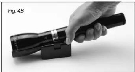
natural_image
Hand holding a flashlight with a black handle, labeled Fig. 4B (no text on device or background)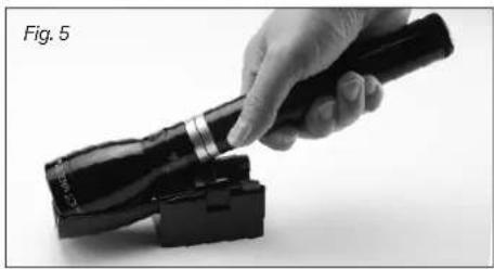
natural_image
Hand holding a flashlight with a black handle, partially attached to a black device (no visible text or symbols)Sección 3
Instalación
Instalación Común
natural_image
Black plastic mechanical component with cutaway view, labeled Figura 6 (no text or symbols on the component itself)natural_image
Close-up of a black plastic electronic device with a cable, labeled 'Figura 10' (no other text or symbols visible)Sección 4