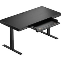
ERDS4-01 - Office ErgoAV - Free user manual and instructions
Find the device manual for free ERDS4-01 ErgoAV in PDF.


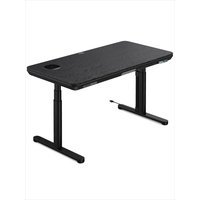
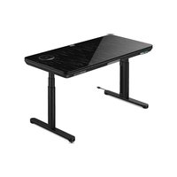
| Product Type | Electric sit-stand desk |
| Brand | ErgoAV |
| Model | ERDS4-01 |
| Height adjustment range | 70 to 118 cm (27.6 - 46.5 in) |
| Maximum speed | 18 mm/s |
| Maximum load (desk + items) | 70 kg (154 lb) |
| Maximum monitor weight | 6.3 kg (14 lb) |
| Power supply | 100-240V AC |
| Main functions | Motorized adjustment, 4 height memory, child lock, anti-collision detection |
| USB ports | 1x USB-A (5V 2A) and 1x USB-C (9V 2A) |
| Control | Control panel with digital display |
| Protection | Overcurrent (E01), undervoltage (E12), overheating (H01), sensor malfunction (E07) |
| Included accessories | Drawer, cable management tray, cable clips, Allen key, screws, wall plugs |
| Materials | Steel frame, particle board desktop |
| Care and cleaning | Wipe with a soft, dry cloth; do not use abrasive products |
| Safety | Clear any obstacles before use; check cable length |
| Spare parts and repairability | Contact support for parts: (877) 419-7832 or support@ergoav.com |
| General information | Manual available in French, English, Spanish |
Frequently Asked Questions - ERDS4-01 ErgoAV
User questions about ERDS4-01 ErgoAV
0 question about this device. Answer the ones you know or ask your own.
Ask a new question about this device
Download the instructions for your Office in PDF format for free! Find your manual ERDS4-01 - ErgoAV and take your electronic device back in hand. On this page are published all the documents necessary for the use of your device. ERDS4-01 by ErgoAV.
USER MANUAL ERDS4-01 ErgoAV
Electric Standing Desk Instruction Manual
V1
natural_image
Line drawing of a simple desk with two legs and a front panel, no text or symbols presentERDS4-01
Thank you for choosing ErgoAV!
At ErgoAV, our goal is to add value to your AV experience by providing the highest quality products and services in the industry. We offer a 5-year warranty. If you have any questions or concerns, please contact us.

ErgoAV

9501 Louisiana Ave N, #200, Brooklyn Park, MN 55445

(877) 419-7832
Mon-Fri 8am - 8pm (CST)

support@ergoav.com

www.ergoav.com
Specifications
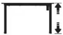
Height Adjustment Range
27.6-46.5" (70-118cm)

Power Input
100V-240V

Max. Speed
18mm/s
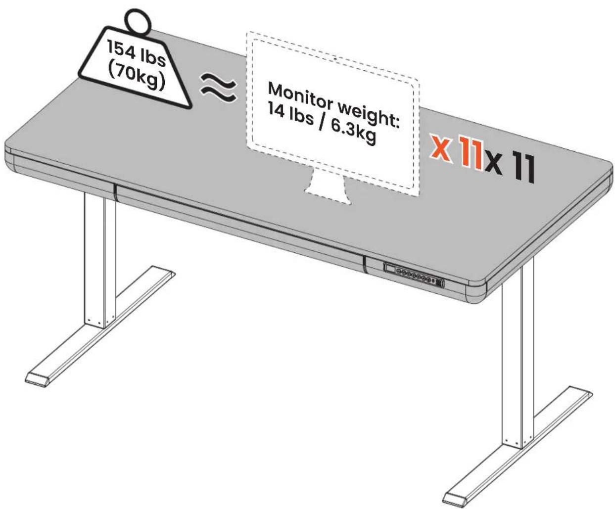
Max. Load
154 lbs / 70kg (Desktop + Other Items)
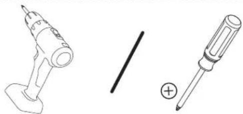
Tools Needed (Not Included)
natural_image
Line drawings of a drill pen and a screwdriver with a plus symbol (no text or labels)Step 1 Supplied Parts and Hardware
A x 8
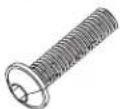
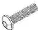
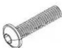
Bolt M6 x 30mm
B x 10

Bolt M6 x 10mm
C x1
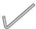
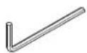
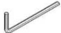
Allen Key 5/32" (4mm)
1 x 1
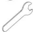
Wrench
K1 x 2

Set Screw
K2 x 1
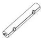
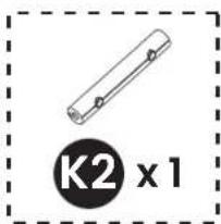
Rod Coupler
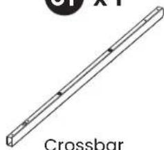
01 x 1
natural_image
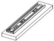
Simple line drawing of a crossbar with no text or symbolsCrossbar
02 x 1
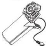
Motor
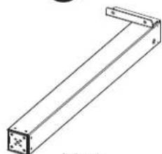
03 x 1
natural_image
Technical line drawing of a mechanical bracket or support structure (no text or symbols)L Leg
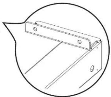
natural_image
Technical line drawing of a metal bracket component (no text or symbols)04 x 1
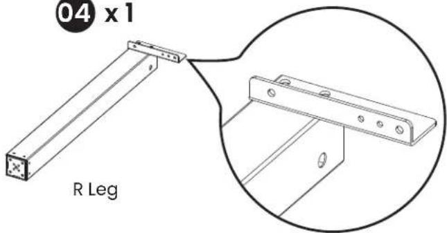
R Leg
05 x 1

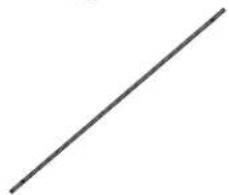
Transmission Rod
06 x 1
natural_image
Single straight black line on white background (no text or symbols)Transmission Rod
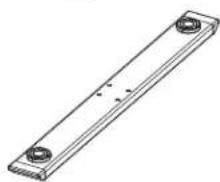
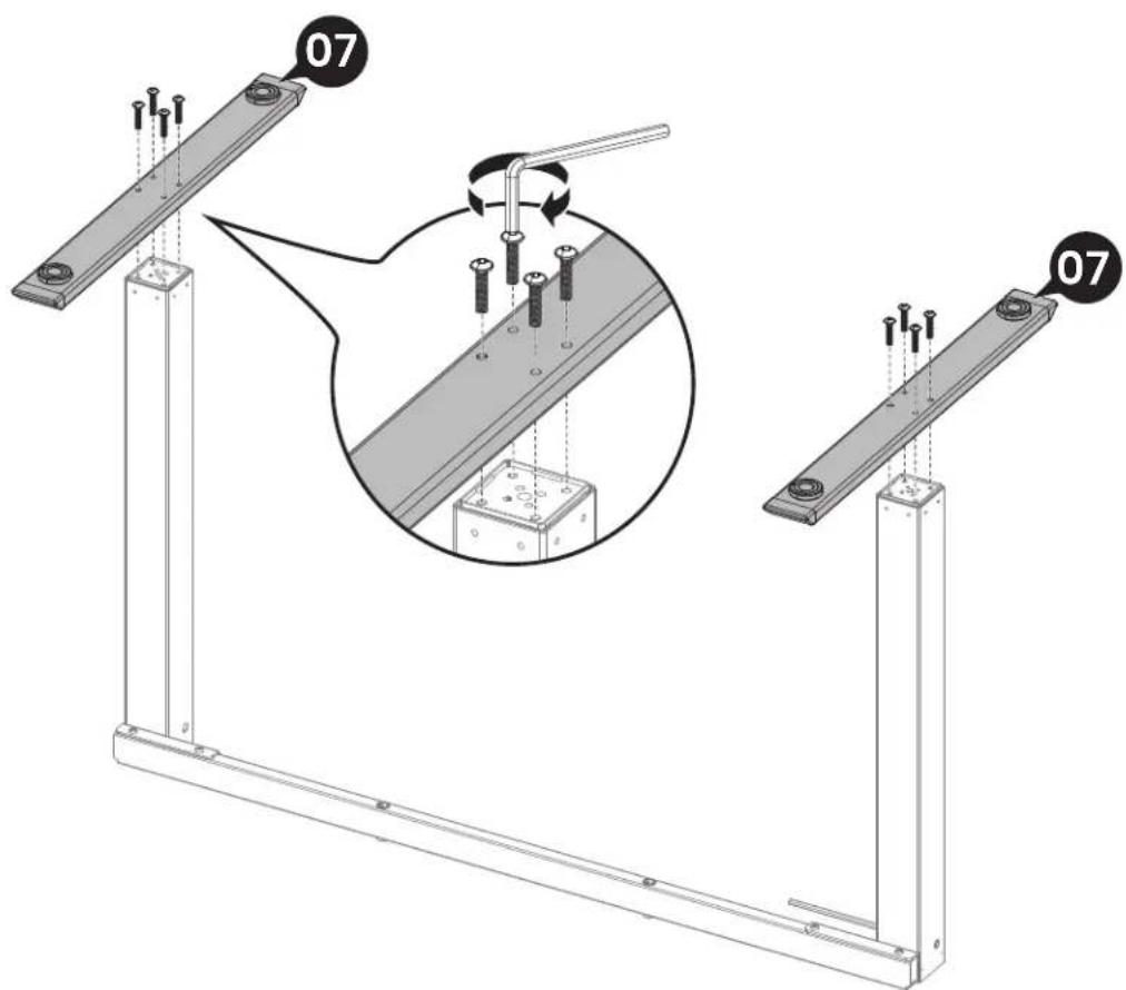
07 x 2
natural_image
Technical line drawing of a rectangular metal plate with two circular holes (no text or symbols)Leg Base
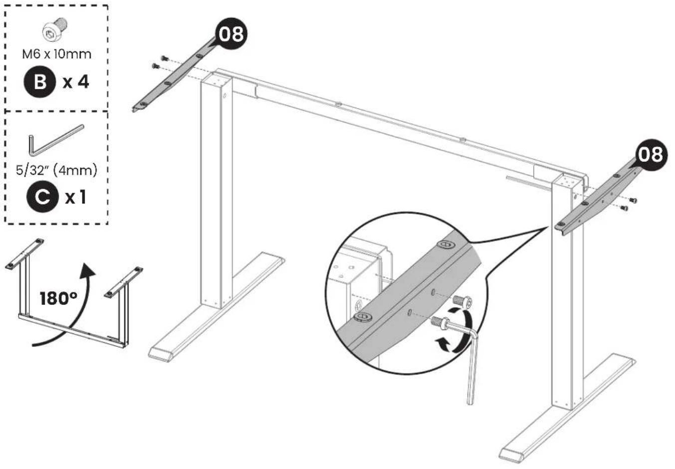
08 x 2
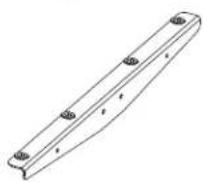
Side Plate
Step 2
Supplied Parts and Hardware

x1
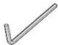
Allen Key 5/32" (4mm)

x14

Bolt M6 x 14mm

x2
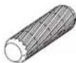
Wood Dowel

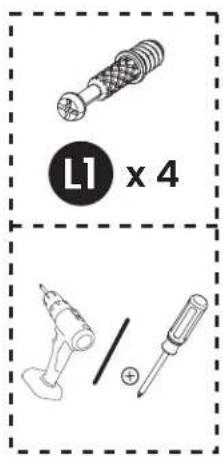
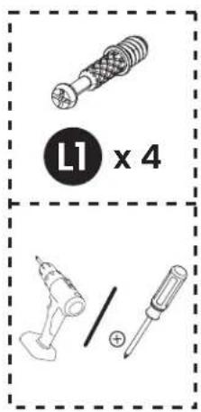
x4
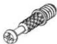
Cam Bolt

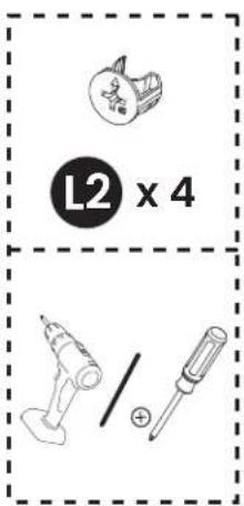
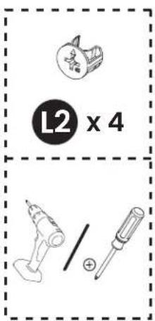
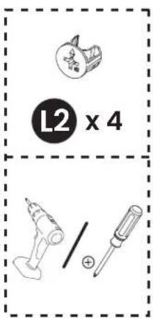
x 4

Cam Lock

x2
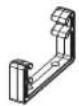
Tray Bracket

x1
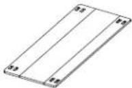
Cable Management Tray

x1
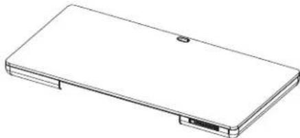
natural_image
Line drawing of a rectangular electronic device with a small internal component (no text or symbols)Desktop

x1
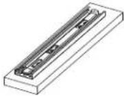
Drawer Support Panel

x1
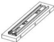
Drawer Support Panel
Step 3
Supplied Parts and Hardware

x4

Cable Clip

x1
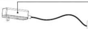
Actual part may vary.
Power Cable
Step 4
Supplied Parts and Hardware

x1

Drawer
Not all hardware included in this package will be used.
Contact Us
If you receive parts that are damaged, defective, or are missing parts, please contact us.

(877) 419-7832 Mon-Fri 8am - 8pm (CST)

support@ergoav.com
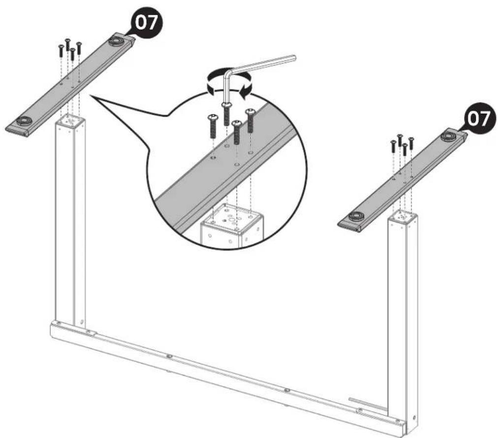
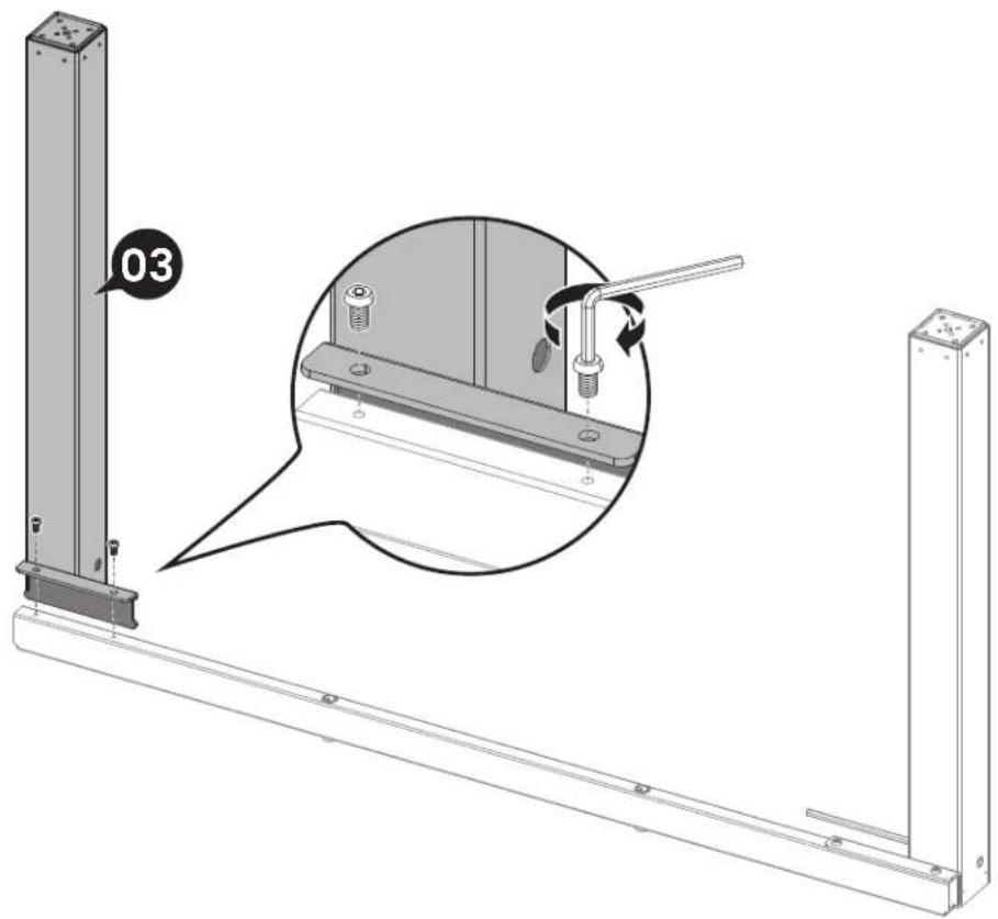
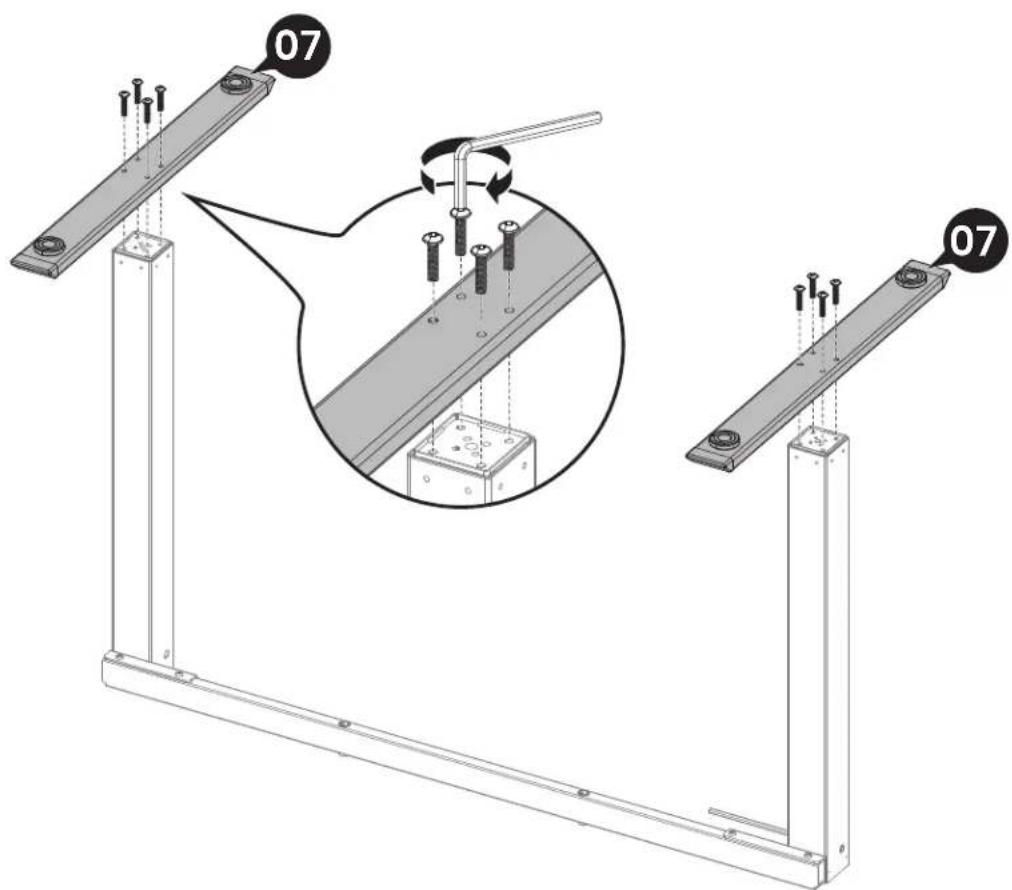
Step 1 Assembling the Frame
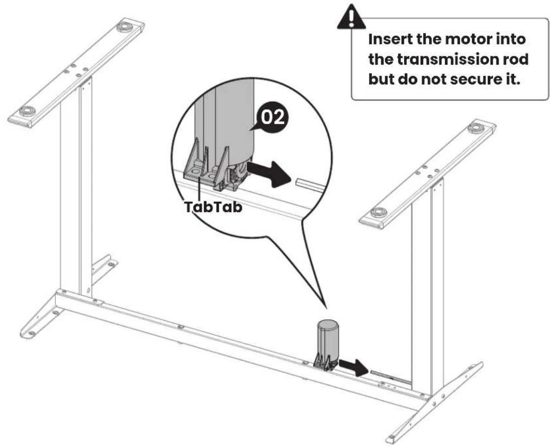
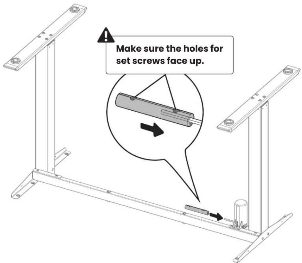
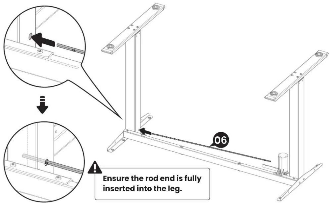
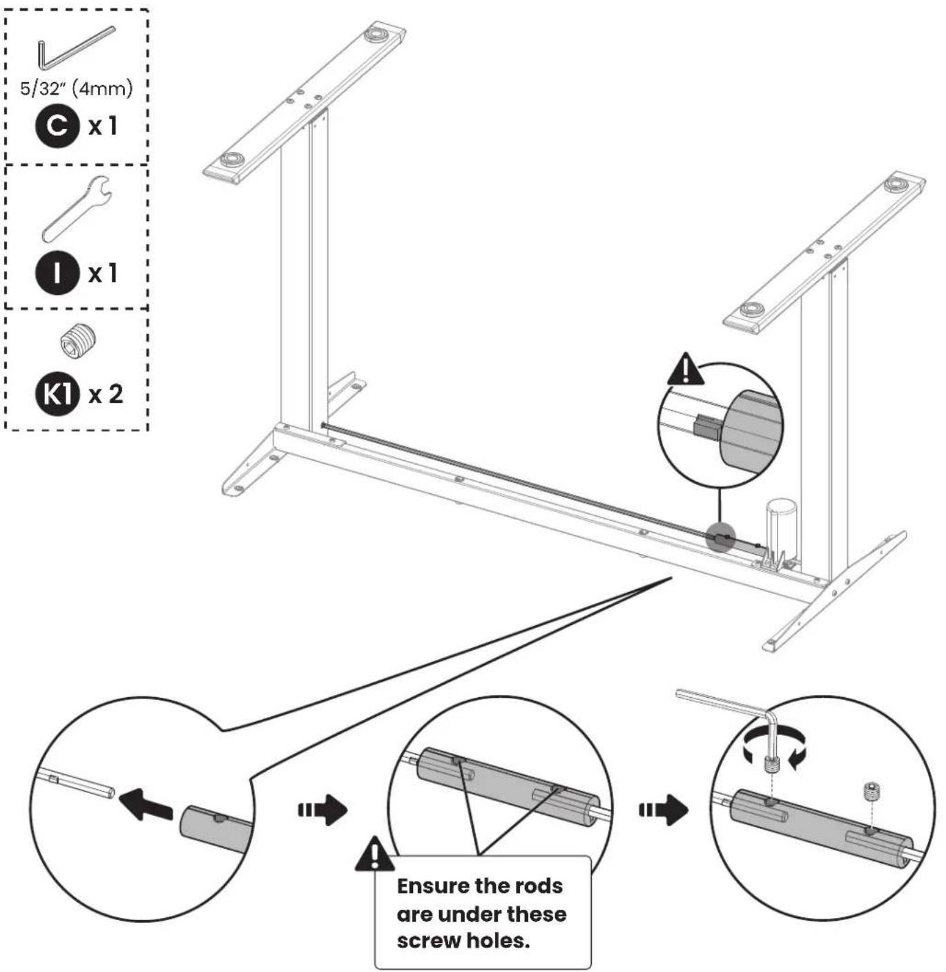
Connect the short transmission rod to the R leg.
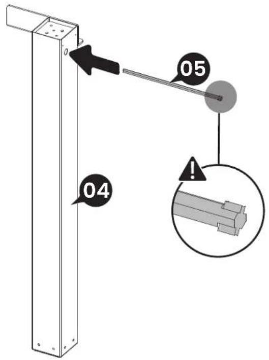

M6 x 10mm

x2
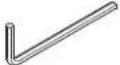
5/32" (4mm)

x1
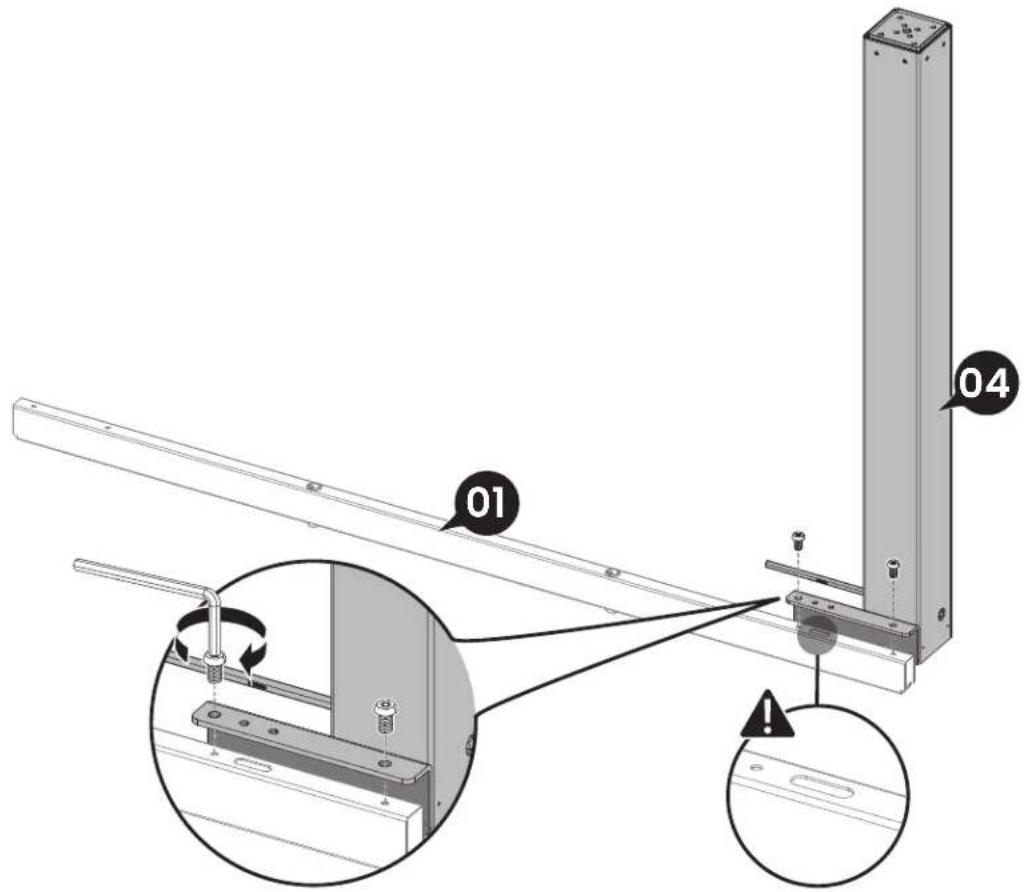

M6 x 10mm

5/32" (4mm)

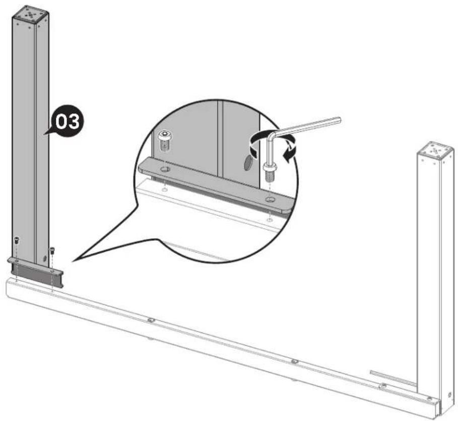
M6 x 30mm
5/32" (4mm)

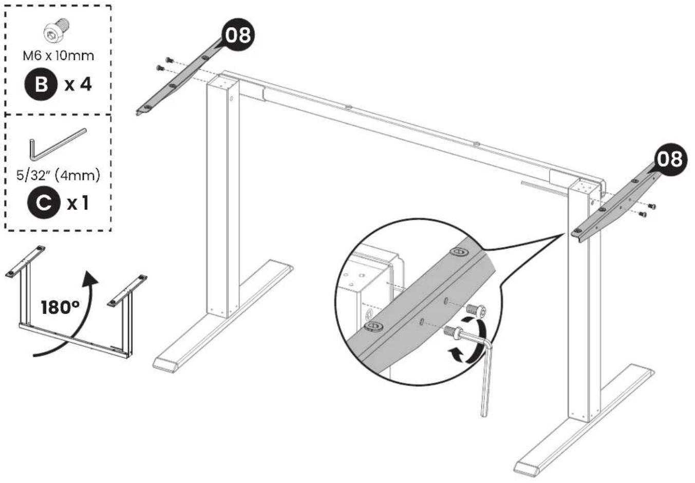
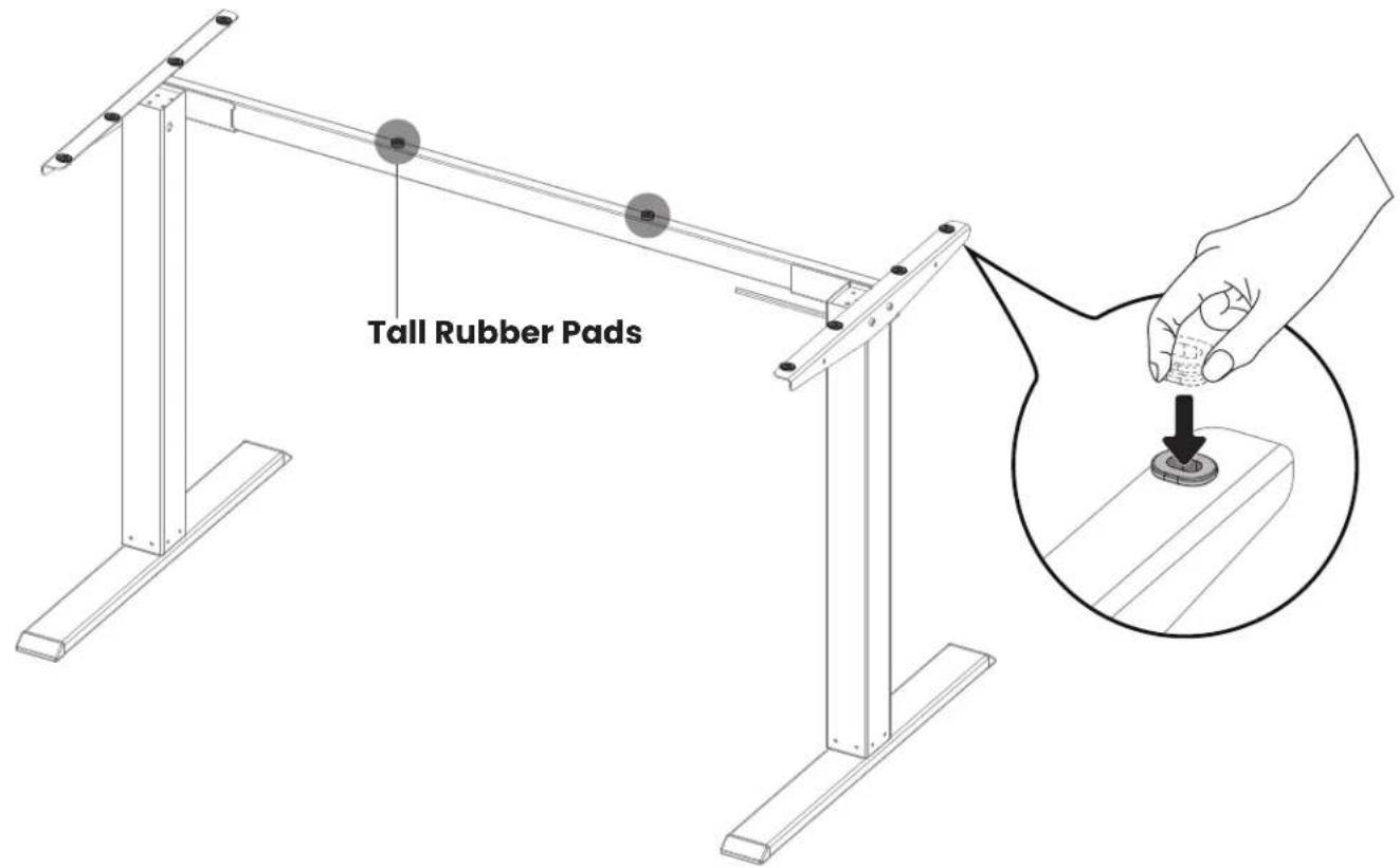
Ensure the rubber pads are attached to the frame. If any have fallen off, reattach them or use the spare rubber pads.
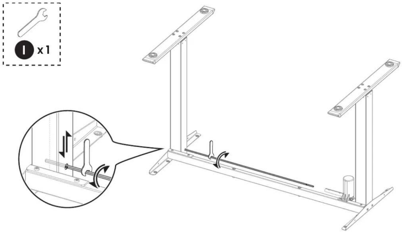
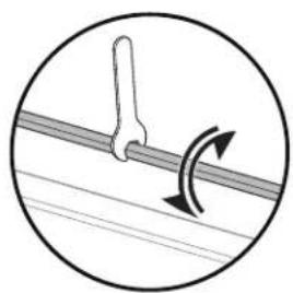
Adjust uneven desk legs if needed:
Measure the height of each leg to see if they are set at the same level. If not, turn the rod to raise or lower the leg until it's level with the leg with motor.

natural_image
Diagram showing a tool interacting with a curved mechanical component, enclosed in a circle (no text or symbols)If the transmission rod does not fit smoothly, use the wrench to fine-tune the position.

M6 x 10mm

x2
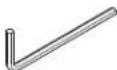
5/32" (4mm)

x1
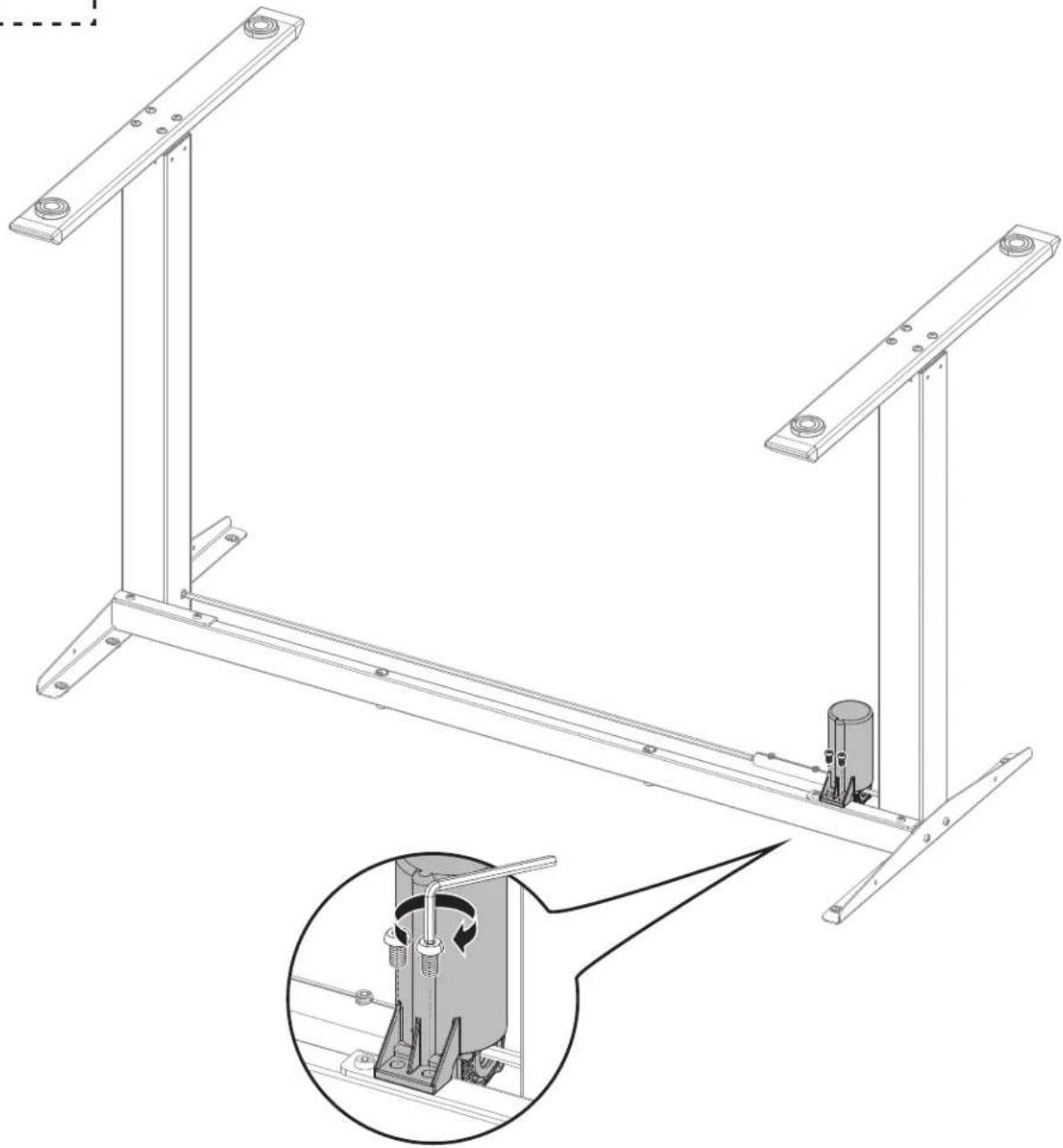
natural_image
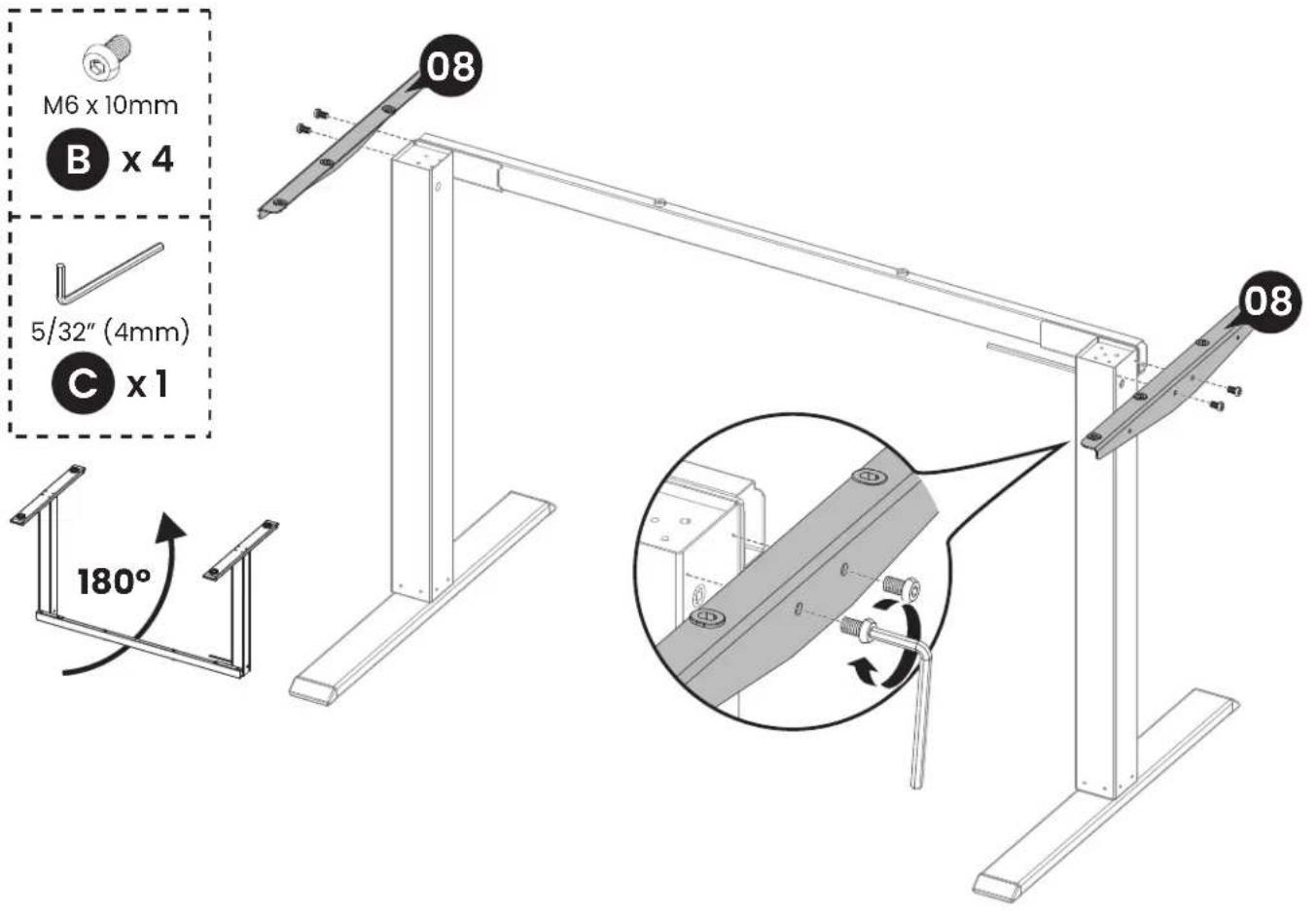
Technical line drawing of a mechanical assembly with two metal frame supports and a central cylindrical component, plus an inset showing a rotating mechanism (no text or symbols)Step 2 Attaching the Desktop and Other Parts

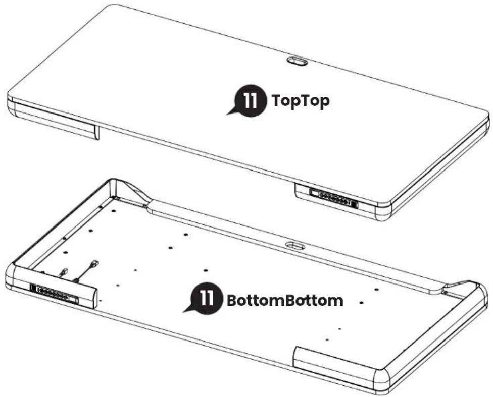
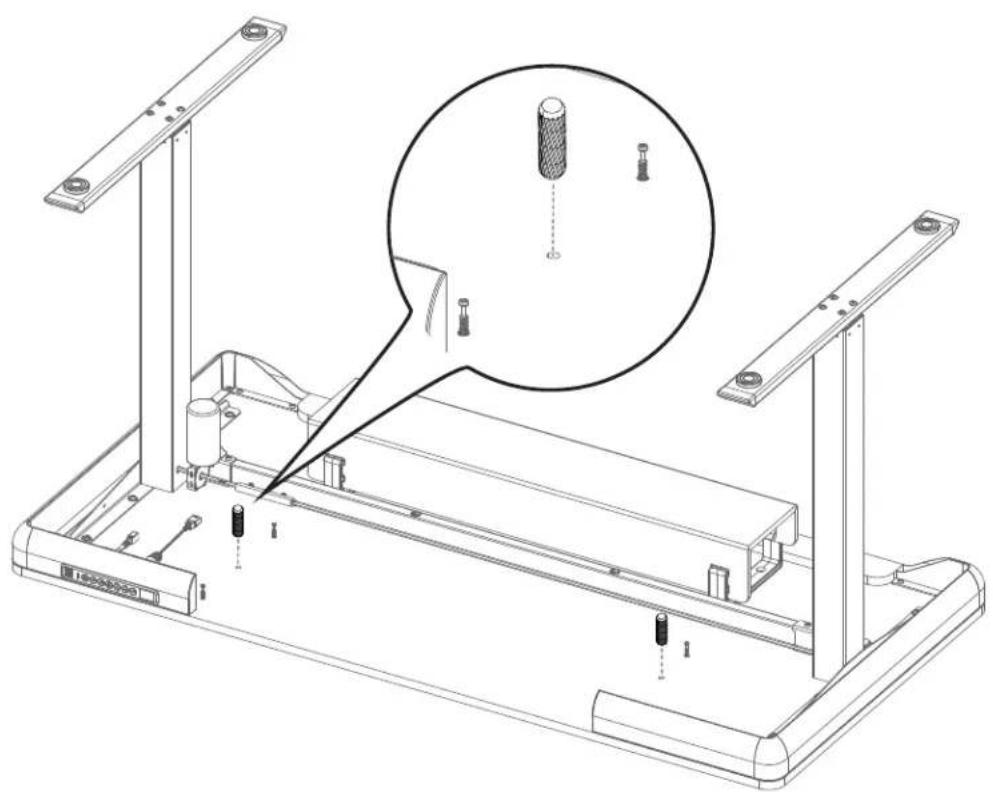
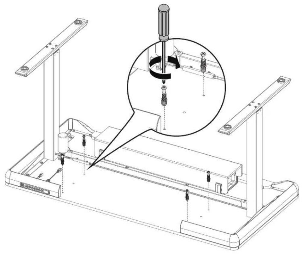
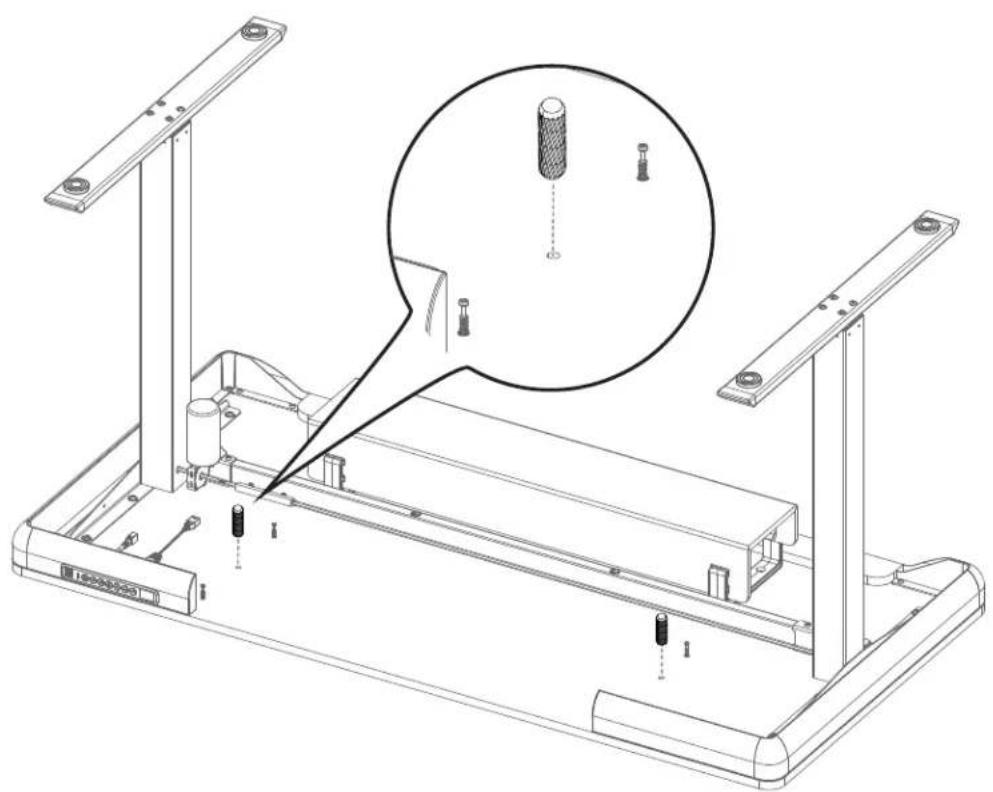
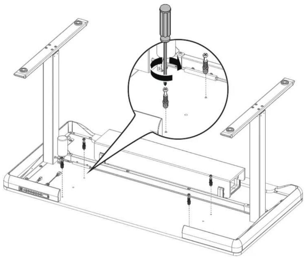
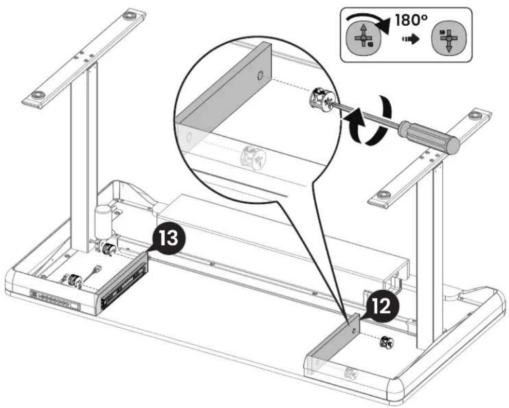
Tip: ● indicate pre-drilled hole locations.
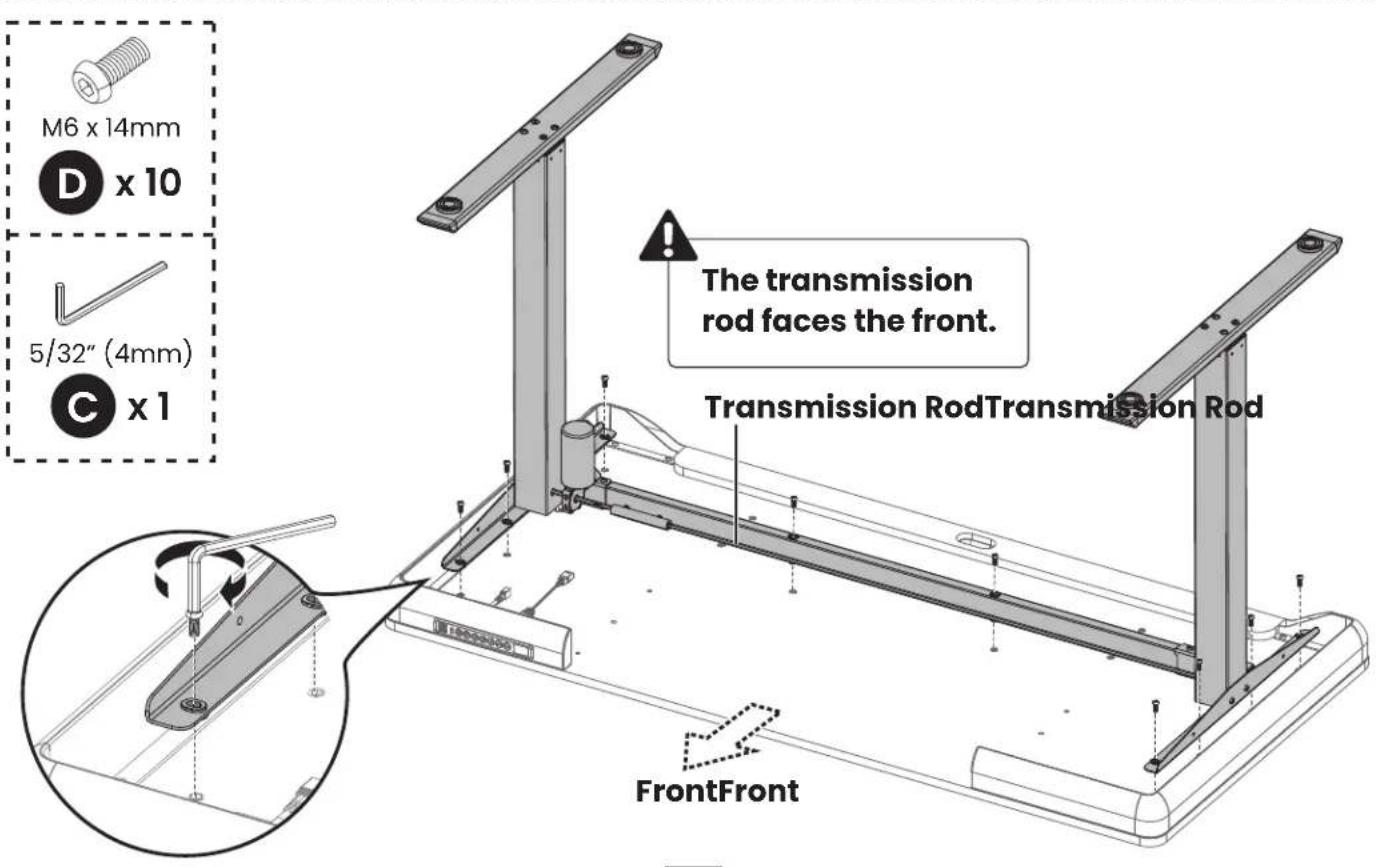

M6 x 14mm

x 4
5/32" (4mm)

x1

natural_image
Technical line drawing of a mechanical assembly with a magnified inset showing a tool interacting with a component (no text or symbols present)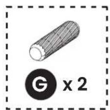
natural_image
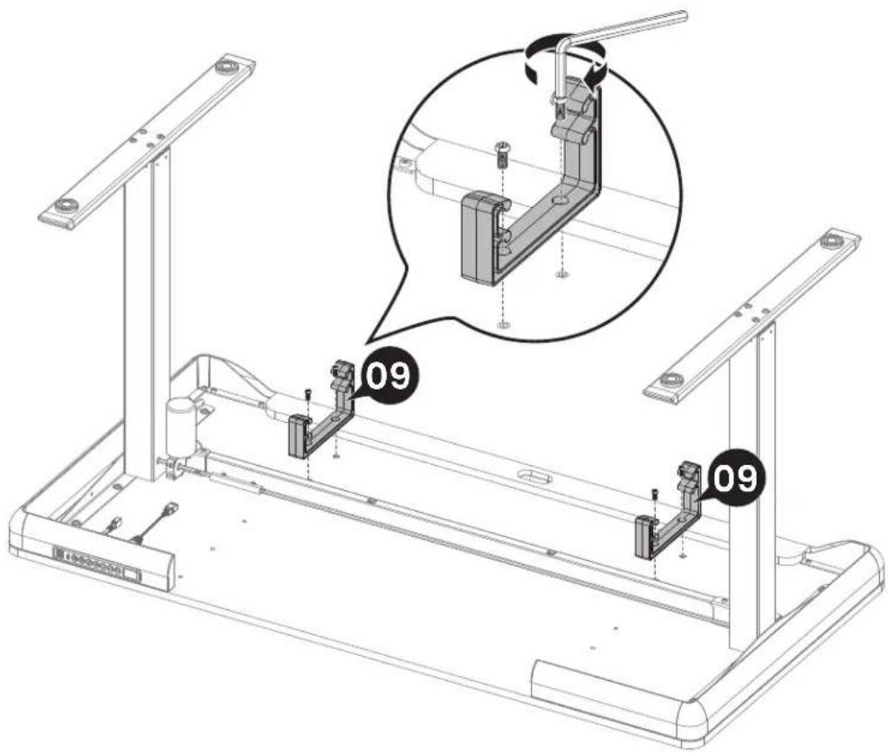
Technical line drawing of a mechanical assembly with mounting brackets and a magnified inset showing a cylindrical component (no text or symbols present)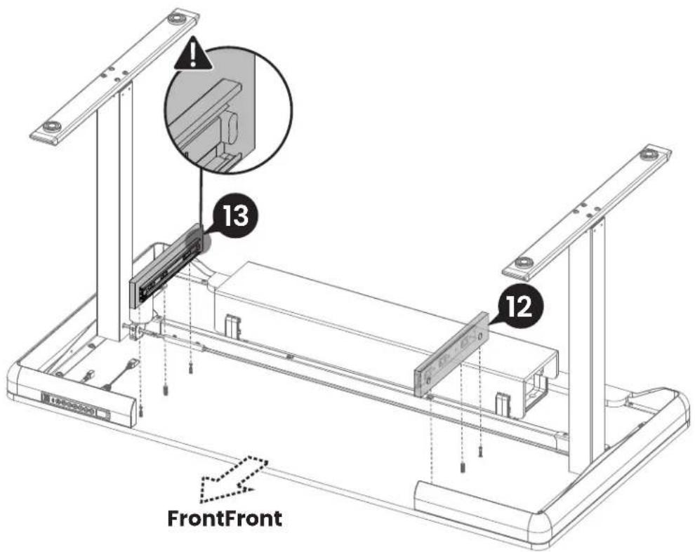
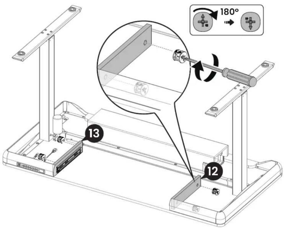
Step 3 Connecting the Cables

An example of a cable clip layout is indicated below. However, the cable clips can be arranged according to your needs.

H x 4

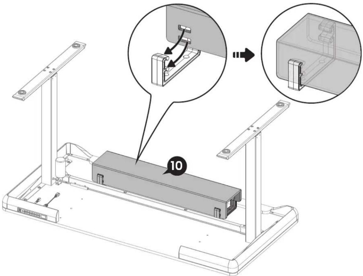
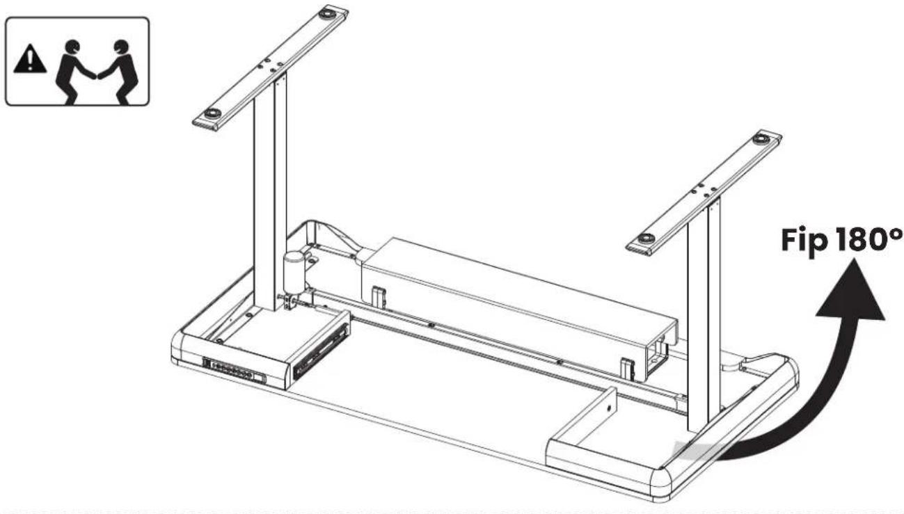
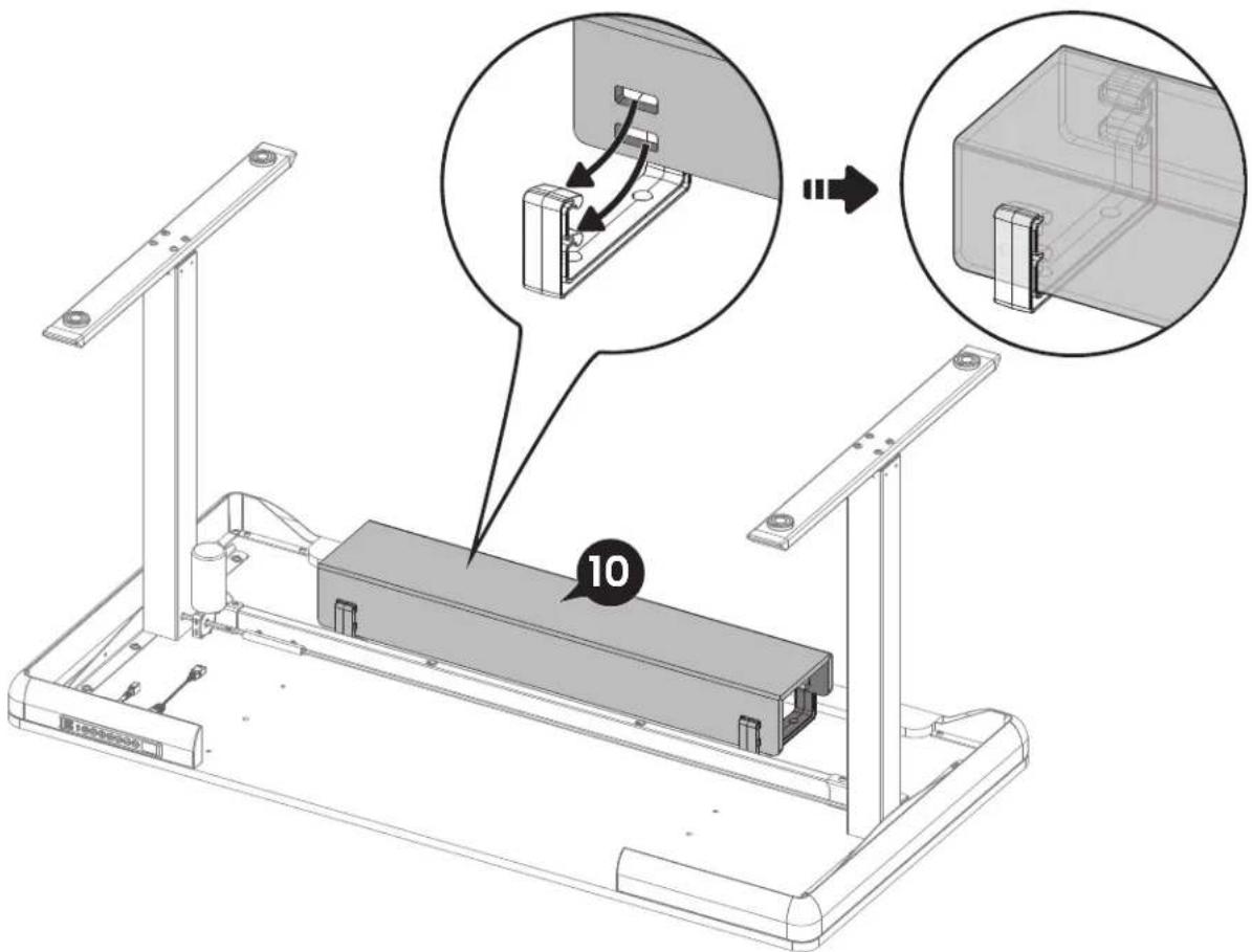
Step 4 Attaching the Drawer
When flipping the desk over, make sure the controller does not hit the ground, which could cause damage.
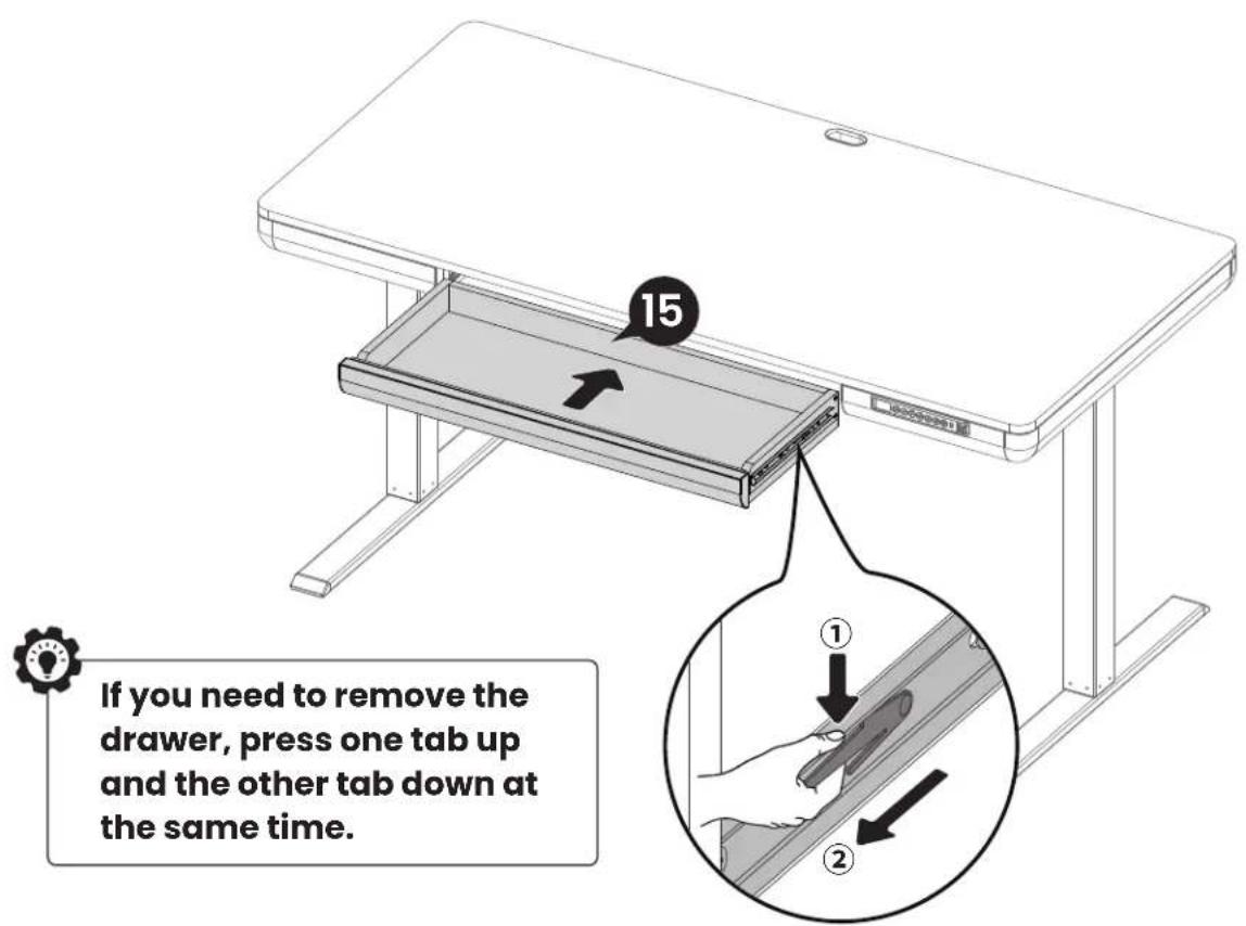

If you need to remove the drawer, press one tab up and the other tab down at the same time.
Using the Controller
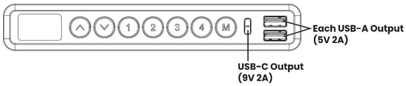

Reset before first use.
Note: Ensure that there are no obstacles when using the desk, that the desktop is not too close to the wall, and that all cables are long enough for the desk to move up and down freely. When the controller screen is off (power-saving mode), press any button to wake it before operation.
Raise Desk (Max height: 46.5"/118cm)
√ Lower Desk (Min height: 27.6"/70cm)
- Save Current Height Setting
Four heights can be saved. Press the Ⓜ button and the screen will display 'S-'. Press the ⑪, ③④, ○, or ○ button, the current height will be saved to that button.
- Select Height Setting
Press the ①2/3④/ ○/ ○ button. The desk will move to the height that was previously set for that button. Press any button to stop the desk.
| Main Settings | |
| Reset | 1. Press and hold the √ button until the desk goes down to its lowest level, then release the button.2. Press and hold the √ button for 5 seconds until the screen displays 'RST', then release the button.3. Press and hold the √ button again until the screen display current height again. Reset is complete. |
| 'RST' displays as RST on the screen. | |
| Set Highest Limit | 1. Press the M button and the screen will display 'S-'.2. Press the ∧ button, the 'S-' will flash once on the screen, then release the button.3. Press and hold the M button for 2 seconds until the screen display '999'. The current height will be saved as the highest limit. |
| Set Lowest Limit | 1. Press the M button and the screen will display 'S-'.2. Press the √ button, the 'S-' will flash once on the screen, then release the button.3. Press and hold the M button for 2 seconds until the screen display '00.0'. The current height will be saved as the lowest limit. |
| Clear Highest/ Lowest Limit | 1. Press the M button and the screen will display 'S-'.2. Press and hold the M button for 2 seconds until the screen display '555'. The highest/lowest limit will be cleared. |
| Lock/Unlock | Press and hold the M button for 8 seconds to turn the lock on. The screen will display 'LOC', and the buttons will be disabled. Repeat to turn the lock off. |
Other Settings
To adjust the settings below, follow the reset instructions until the display flashes 'RST'. Next, follow the instructions below to adjust individual settings. After adjustment, the screen will flash 'RST' again. To exit, press and hold the √ button until the desk goes down to its lowest level and comes back up slightly. The screen will display the current height.
- Change Collision Detection Sensitivity
Press and hold the ⬆ button for 5 seconds to switch sensitivity level.
10.5: High Sensitivity
10.6: Medium Sensitivity
10.7: Low Sensitivity
Note: Sensitivity is preset to Normal (Low Sensitivity) by the factory. However, sensitivity may be adjusted if needed.
- Change Display Height Units
Press and hold the ② button for 5 seconds to switch the display height units. The default unit is imperial.
10.3: Metric (cm)
10.4: Imperial (inch)
- Change Displayed Minimum Height
Press and hold the Ⓜ button for 5 seconds. The current minimum height will flash on the screen. Press the ∧ or √ button to adjust the minimum height, then release the button. After 5 seconds, the screen will display 'RST' again.
Protection Mode Error Codes
| E01 | Overcurrent Protection: Input current too high. If the correct AC adapter is being used, perform a reset before continue using. |
| E07 | Sensor Malfunction Warning: Motor safety sensor cannot be detected. Power off, check motor cable and power cable connections, power back on again, then reset. |
| E12 | Undervoltage Protection: Input voltage too low. If the correct AC adapter is being used, perform a reset before continue using. |
| H01 | Overheating Protection: When the motor overheats or the motor has been working continuously for too long (total 2.5 minutes in 20 minutes), it will stop operating to prevent damage from overheating. Wait at least 18 minutes or until the motor cools down before making any further height adjustment. |
Please try resetting the controller if you have any issues including the following:
- Abnormal operation.
- The controller screen displays an error message.
Spécifications
natural_image
Line drawings of a drill pen and a screwdriver with a plus symbol (no text or labels)Étape 1
Clé Allen 5/32" (4mm)
1 x 1
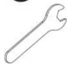
Clé
K1 x 2

Vis de réglage
K2 x 1
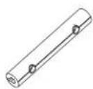
Coupleur de tige
01 x 1
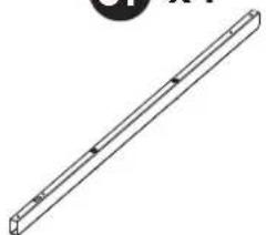
natural_image
Simple line drawing of a long rectangular object with four evenly spaced square holes, no text or symbols present.Barre transversale
02 x 1
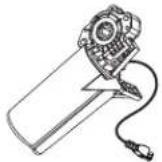
Moteur
03 x 1
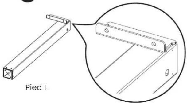
natural_image
Technical line drawing of a structural bracket labeled 'Pied L', showing a 3D view with an inset close-up of its detail (no text or symbols beyond label)04 x 1
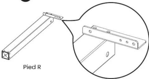
natural_image
Technical line drawing of a metal bracket labeled 'Pied R' with an inset close-up view (no text or symbols beyond label)05 x 1

Tige de transmission
06 x 1

natural_image
Single diagonal line on white background (no text or symbols)Tige de transmission
07 x 2
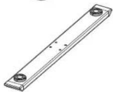
natural_image
Technical line drawing of a rectangular metal plate with two circular holes (no text or symbols)Base de la jambe
08 x 2
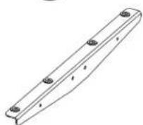
Plaque latérale
Étape 2
natural_image
Line drawing of a rectangular electronic device with a small internal component (no text or symbols)Bureau

x1
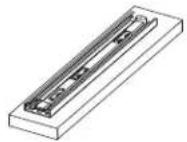

M6 x 10mm

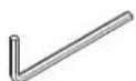
5/32" (4mm)

M6 x 30mm
5/32" (4mm)

natural_image
Technical line drawing of a mechanical frame assembly with a close-up inset showing internal components (no text or symbols)Étape 2
natural_image
Technical line drawing of a mechanical assembly with a magnified inset showing a tool interacting with a component (no text or symbols present)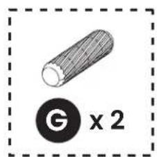
natural_image
Technical line drawing of a mechanical assembly with mounting brackets and a magnified inset showing internal components (no text or symbols)

Étape 3
natural_image
Line drawings of a drill pen and a screwdriver with a plus symbol (no text or labels)C x1
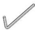
Llave Allen
5/32" (4mm)
1 x 1
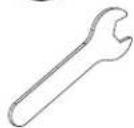
Llave
K1 x 2

Tornillo prisionero
natural_image
Pure technical line drawing of a long rectangular rod or beam with evenly spaced holes (no text or symbols)Barra transversal
02 x1
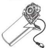
Motor
03 x1
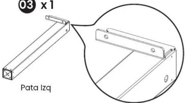
05 x1
natural_image
Simple diagonal line with a small circular symbol above it (no text or labels)Llave Allen 5/32" (4mm)

x14

Perno M6 x 14mm

x2
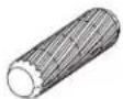
Pasador de madera

x4
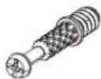
Cerrojo de leva

x 4

Cerradura de leva

x2
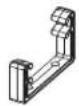
Soporte de bandeja

x1
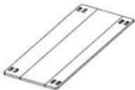
natural_image
Line drawing of a rectangular electronic device with a small internal component (no text or symbols)Escritorio

x1
Not all hardware included in this package will be used.
Contáctenos

M6 x 10mm

5/32" (4mm)

M6 x 30mm
5/32" (4mm)

natural_image
Circular diagram showing a tool interacting with a curved mechanical component, no text or symbols presentnatural_image
Technical line drawing of a mechanical frame assembly with a close-up inset showing internal components (no text or symbols)

natural_image
Technical line drawing of a mechanical assembly with a magnified inset showing a disassembly or disassembly process (no text or symbols present)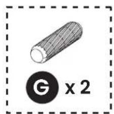
natural_image
Simple line drawing of a cylindrical object with a circular symbol below (no text or labels)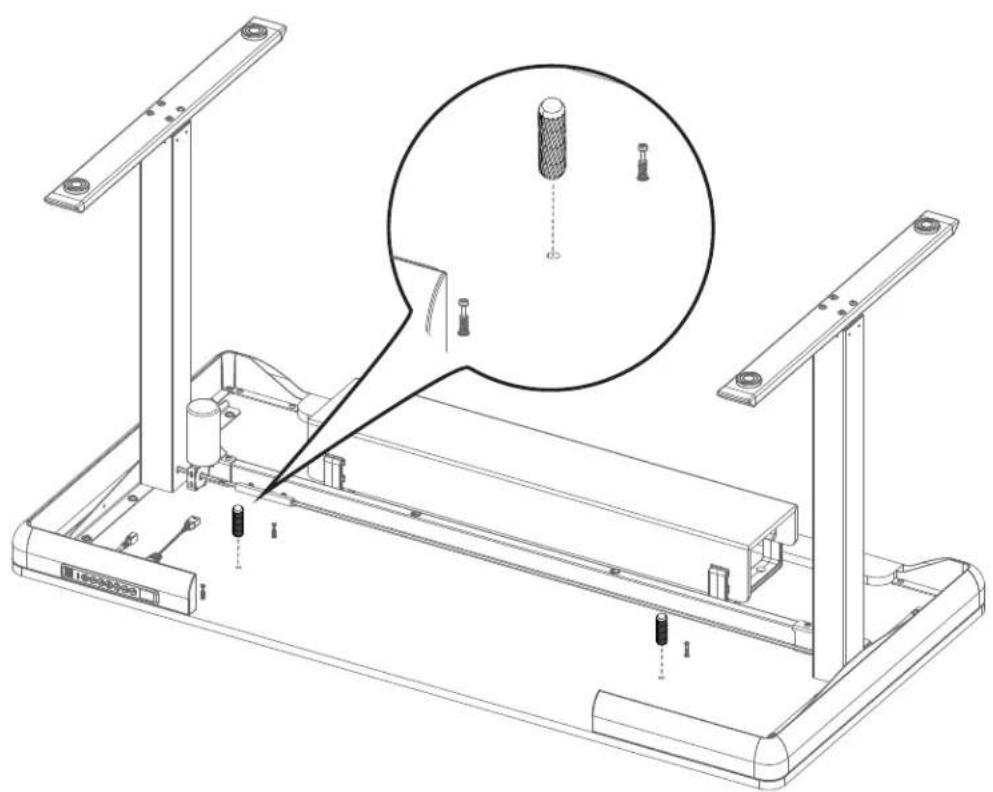
natural_image
Technical line drawing of a mechanical assembly with mounting brackets and a magnified inset showing internal components (no text or symbols)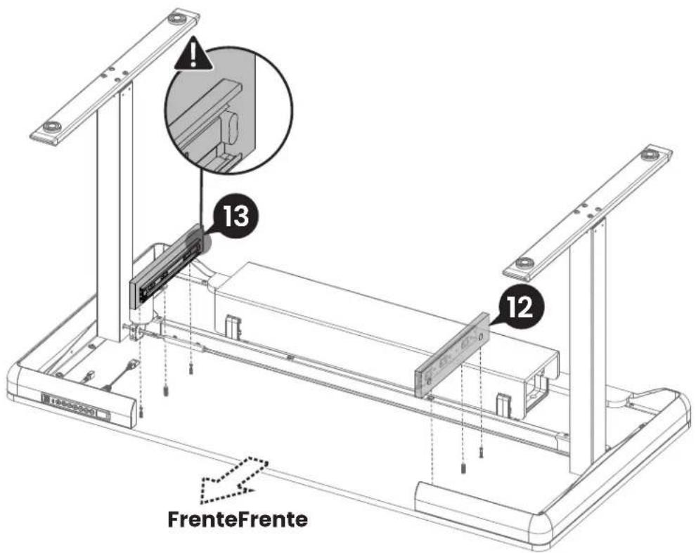
natural_image
Simple line drawing of a mechanical device with a circular symbol below (no text or symbols)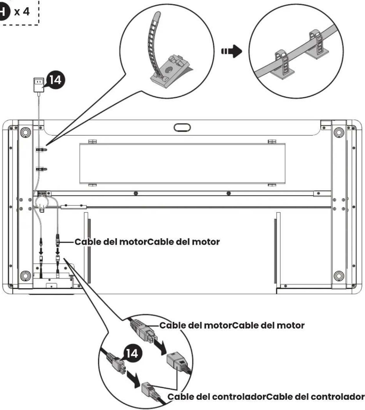
At ErgoAV, our goal is to provide the high-quality audio video solutions and product support that you need. If you have any questions, concerns, or feedback, please let us know!
natural_image
Technical line drawing of a mechanical assembly with no visible text or symbolsTV Mounts
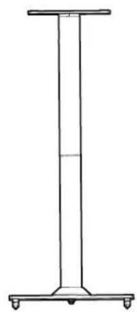
natural_image
Simple line drawing of a vertical cylindrical structure with four wheels at the base (no text or symbols)Speaker Stands
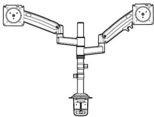
natural_image
Technical line drawing of a Y-shaped mechanical or robotic arm with two arms and a central shaft (no text or symbols)Computer Monitor Mounts
ErgoAV
9501 Louisiana Ave N, #200, Brooklyn Park, MN 55445
(877) 419-7832 Mon-Fri 8am - 8pm (CST)
support@ergoav.com
www.ergoav.com
- Electric Standing Desk Instruction Manual
- ERDS4-01
- Thank you for choosing ErgoAV!
- Specifications
- Max. Load
- Tools Needed (Not Included)
- Step 1 Supplied Parts and Hardware
- Step 2
- Supplied Parts and Hardware
- Step 3
- Step 4
- Contact Us
- Step 1 Assembling the Frame
- Adjust uneven desk legs if needed:
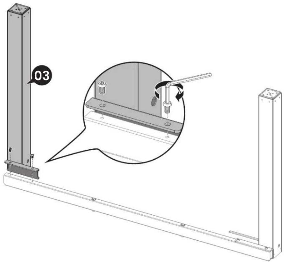
- Step 2 Attaching the Desktop and Other Parts
- Step 3 Connecting the Cables
- Step 4 Attaching the Drawer
- Using the Controller
- - Save Current Height Setting
- - Select Height Setting
- Other Settings
- - Change Collision Detection Sensitivity
- - Change Display Height Units
- - Change Displayed Minimum Height
- Spécifications
- Étape 1
- Étape 2
- Étape 3
- Contáctenos
Brand : ErgoAV
Model : ERDS4-01
Category : Office