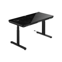
ERDS1-01G - Office ErgoAV - Free user manual and instructions
Find the device manual for free ERDS1-01G ErgoAV in PDF.


| Product Type | Electric Standing Desk |
| Brand | ErgoAV |
| Model | ERDS1-01G |
| Adjustable Height | Yes, via control panel or app |
| Height Memory | 2 presets (above and below 35.5 inches) |
| Sedentary Reminder | Yes, adjustable with on/off |
| Height Limits | Upper and lower adjustable |
| Panel Lock | Yes, with unlock sequence |
| Reset Function | Yes, in case of error |
| Wireless Charging | Yes, with 60° tilt and 30° rotation |
| USB Ports | 2 USB-C (100W max) and 1 USB-A (22.5W max), variable power distribution |
| Power Supply | Electric, integrated motor |
| Cleaning | Dry or slightly damp cloth, do not immerse parts |
| Safety | Do not exceed maximum weight indicated; do not use continuously for more than 2 minutes; disconnect before assembly |
| Parts Supplied | Desk, legs (left/right), feet, cables, protection sleeves, Allen key, protection mat (glass model) |
| Technical Support | Tel. (877) 419-7832 / Email support@ergoav.com |
| Manual Available In | French, English, Spanish and other languages on request |
| App Control | Yes (scan QR code; disable Bixby on Samsung) |
Frequently Asked Questions - ERDS1-01G ErgoAV
User questions about ERDS1-01G ErgoAV
0 question about this device. Answer the ones you know or ask your own.
Ask a new question about this device
Download the instructions for your Office in PDF format for free! Find your manual ERDS1-01G - ErgoAV and take your electronic device back in hand. On this page are published all the documents necessary for the use of your device. ERDS1-01G by ErgoAV.
USER MANUAL ERDS1-01G ErgoAV
Electric Standing Desk Instruction Manual
(A)
English pages 02–12 French pages 13–23 Spanish pages 24–34

natural_image
Line drawing of a simple laptop stand with legs and legs, no text or symbols present
Scan the QR code to download the APP to control the desk.
Model: ERDS1-01G
THANK YOU FOR CHOOSING THIS ERGOAV PRODUCT!
At ErgoAV, we want to add value to your AV experience by providing the highest quality products and services in the industry. If you have any concerns or comments, please contact us.
ErgoAV Customer Care
phone (877) 419-7832
email: support@ergoav.com
website: www.ergoav.com
address: 9501 Louisiana Ave N, #200, Brooklyn Park, MN 55445

NOTE
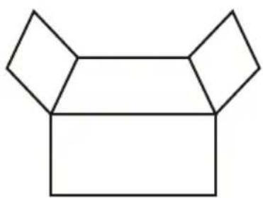
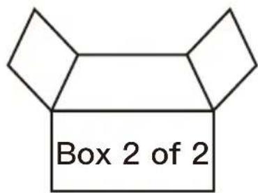
We have packaged this standing desk into two separate parcels. Please make sure to receive both parcels before assembling the desk.
natural_image
Geometric diagram of a 3D shape resembling a dog head with two pentagons and a rectangular body (no text or symbols)Standing DesktopBox 1 of 2
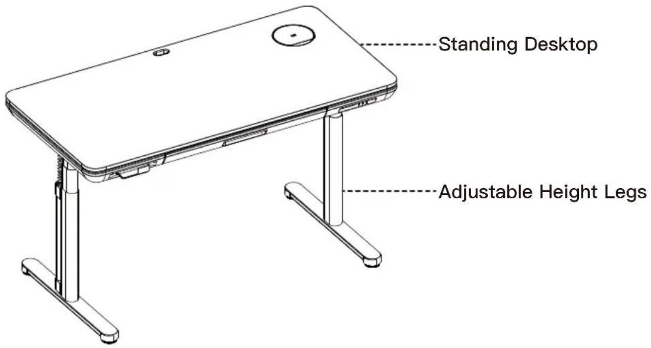
Adjustable Height Legs
Important Safety Information
- Please carefully read all instructions before attempting installation. If you do not understand the instructions or have any concerns or questions, please contact our Technical Support line at (877) 419-7832 or Customer Service at support@ergoav.com.
▲CAUTION: Use with products heavier than the maximum weights indicated may result in instability causing possible injury. - Please check whether the packaging contents are intact or damaged before assembly.
- Check whether the appearance and wires of the product are damaged. If there is any damage, please do not assemble or operate the product.
- Ensure that the product is not connected to a power source during the assembly process.
- Ensure that there are no unnecessary obstacles near the assembly area.
- Do not soak any parts in liquid, only use a dry cloth or a slightly wet cloth to clean product parts.
- Do not place any wires on a heat source.
- Be careful to avoid electric shock when plugging in the power.
- Please do not operate the desk continuously for more than two minutes to prevent damage to the motor.
Weight Restrictions
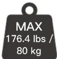
If your products weighs more, do not use this product.
WARNING
DO NOT exceed the maximum weight indicated. This desk is intended for use only within the maximum weight indicated. Use with products heavier than the maximum weight indicated may result in failure of the desk and its accessories, causing damage and or injury.
Supplied Parts and Hardware

Warning: This product contains small items that could be a choking hazard if swallowed.
Before starting assembly, verify all parts are included and undamaged. Do not use damaged or defective parts. If you require replacement parts, please contact our Technical Support line at (877) 419-7832 or Customer Service at support@ergoav.com
- Please note: Not all hardware included in this package will be used.
Supplied Parts and Hardware
natural_image
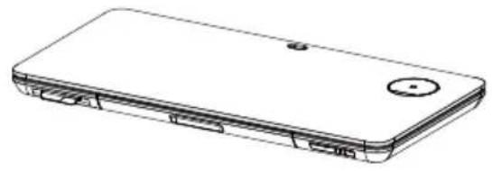
Line drawing of a rectangular electronic device with a circular button and internal components (no text or symbols)Desktop
01 x1
natural_image
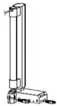
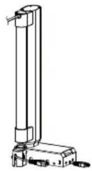
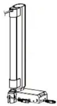
Technical line drawing of a vertical cylindrical device with base and mounting base (no text or symbols)Left Leg
02 x1
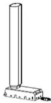
natural_image
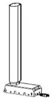
Simple line drawing of a cylindrical object mounted on a base with a small protrusion at the bottom (no text or symbols)Right Leg
03 x1
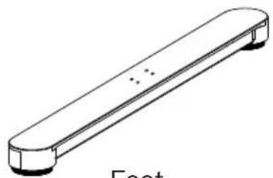
natural_image
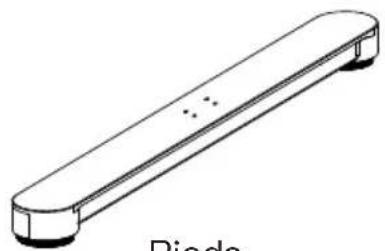
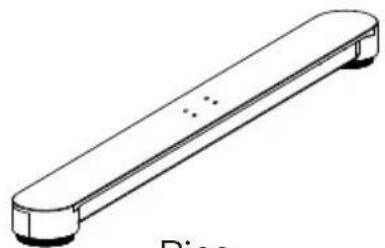
Simple line drawing of a horizontal bar with two ends and a small dot on the top (no text or symbols)Feet
04 x2
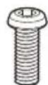
Bolts M6 x 16
A x8
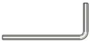
natural_image
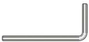
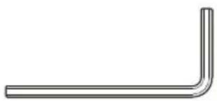
Simple L-shaped metal angle bracket (no text or symbols)Allen Wrench
B x1
Step 1
Place the Desktop [01] assembly on a clean and flat ground, arrange it according to the diagram, and remove the covers on the left and right sides.

Step 2
The Legs [02]&[03] are pre-tilted according to the view, and the grooves on both sides of the rear end are used to snap into the protruding parts on both sides of the side plate. Rotate and press the legs downward. After the legs are installed, connect the power cable as shown.
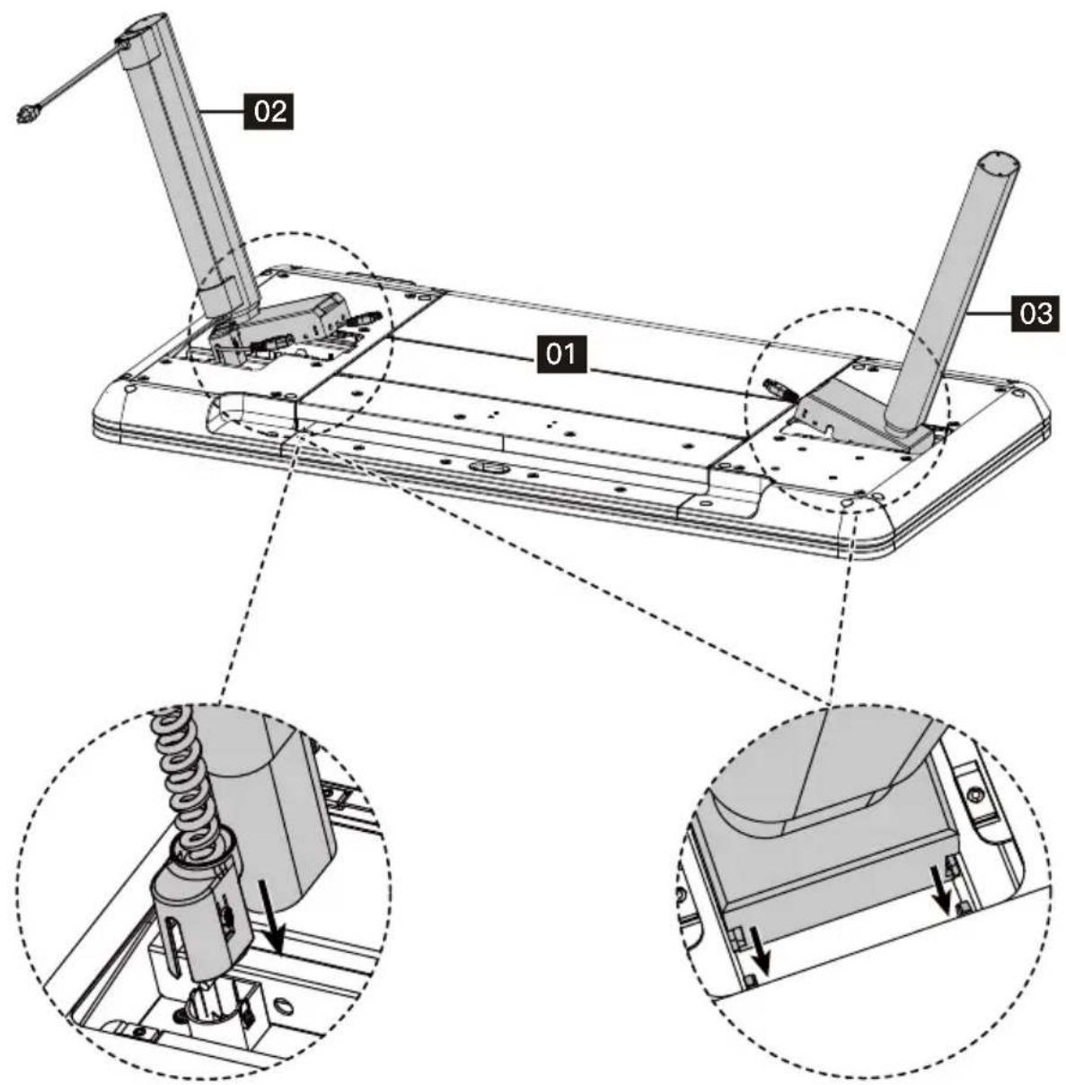
Before installing the left leg, press down the power cable first.
Snap into the protruding parts on both sides of the side plate.


HEAVY! You may need assistance for this step. When pressing down the power cable, you need a assistance to hold the table leg.
Step 3
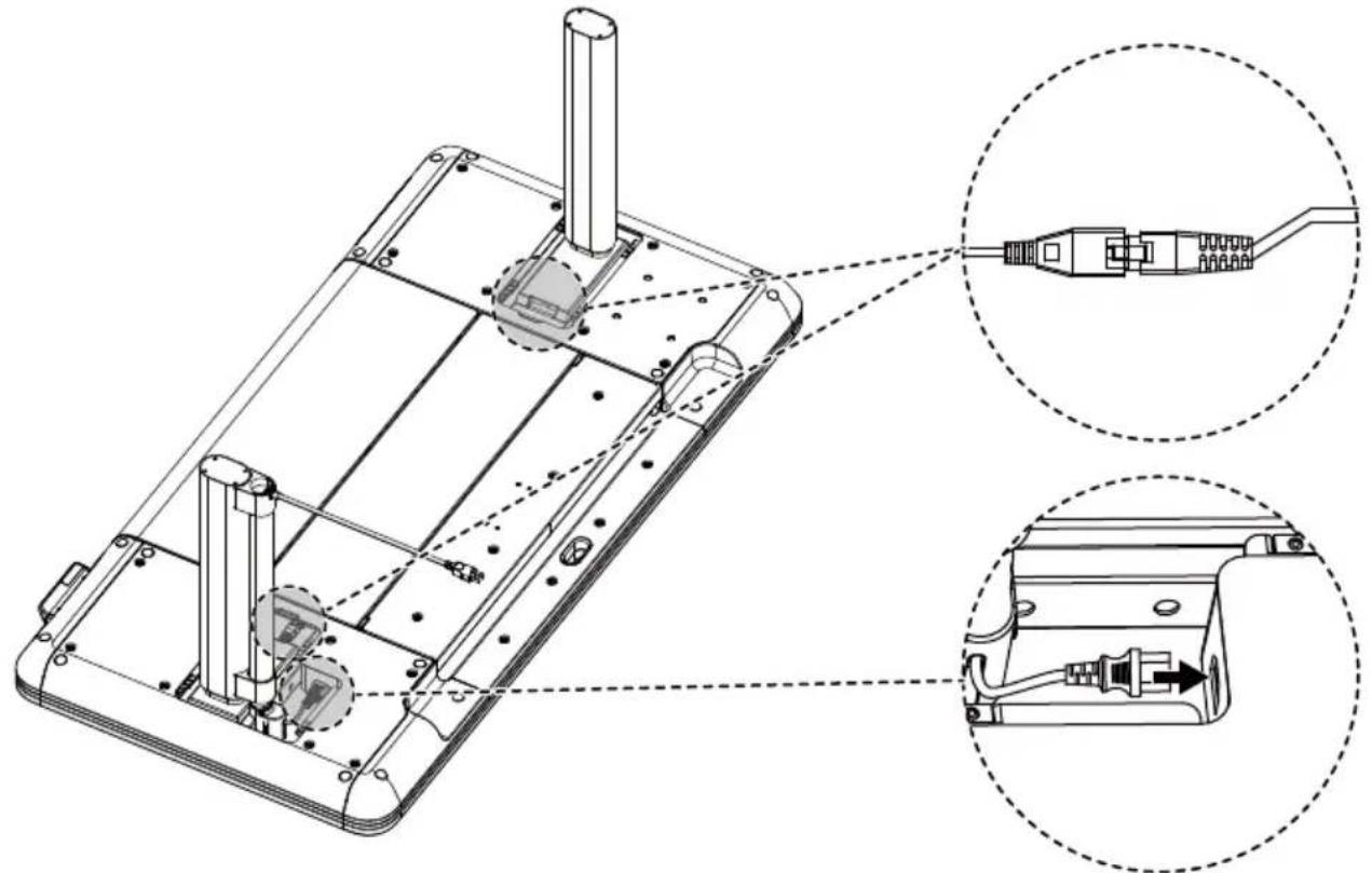
The power cords from the left and right legs should be connected to the power cords on both sides of the desktop. Then connect the plug of the spring cable to the desktop.
natural_image
Technical line drawing of a device chassis with internal components and two magnified views (no text or symbols)Step 4
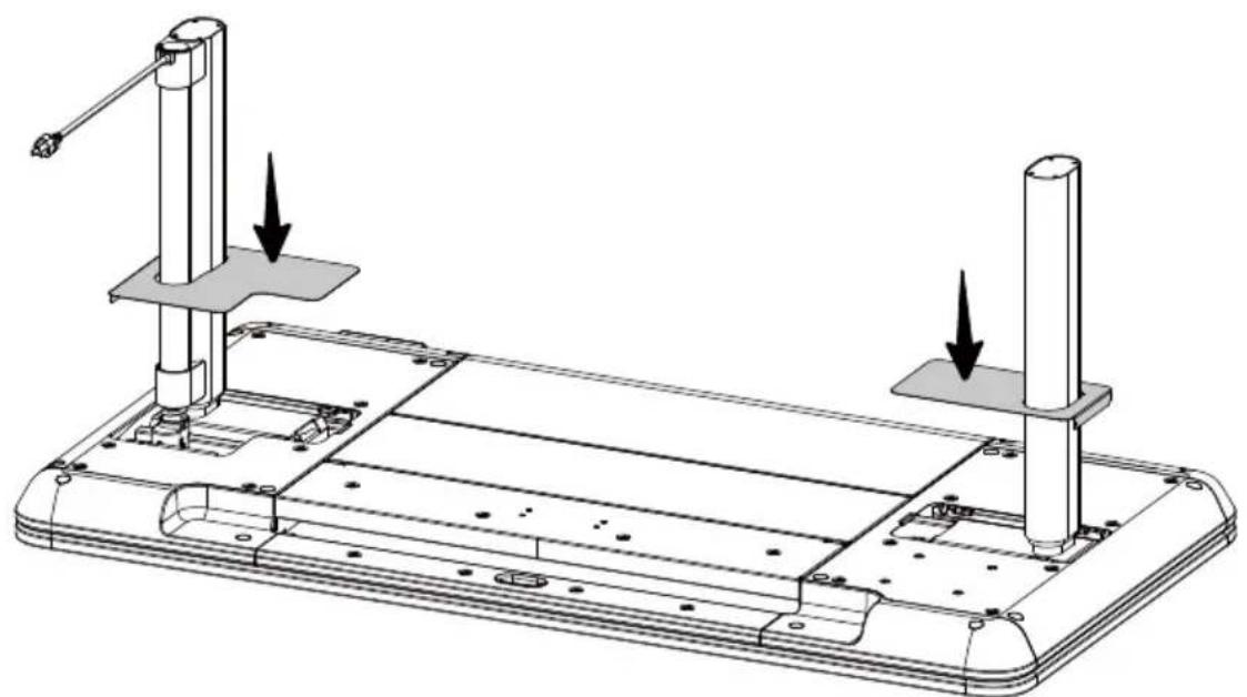
After installing the Legs, insert the left and right cover sleeves, which will be attracted to the magnetic surface at the bottom.
natural_image
Technical line drawing of a mechanical assembly with two vertical supports and mounting holes, showing no text or symbols.Step 5
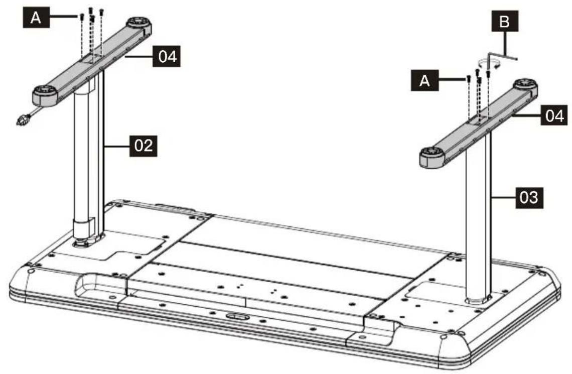
Tighten the Bolts [A] with a Allen Wrench [B] to install the Feet [04] onto the Legs [02]&[03].
Step 6
After the installation of the table is completed, it needs to be flipped over. It is necessary to flip it from the other side of the controller to avoid damaging the controller under pressure.
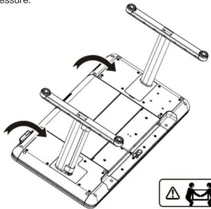


HEAVY! You may need assistance with this step.
CAUTION!
natural_image
3D rendering of a rectangular metal plate with a small circular hole on top (no text or symbols)Desktop Protector Pad
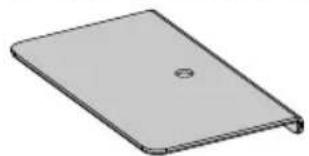
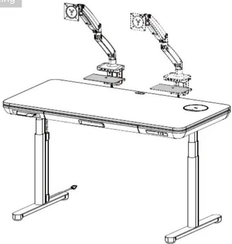
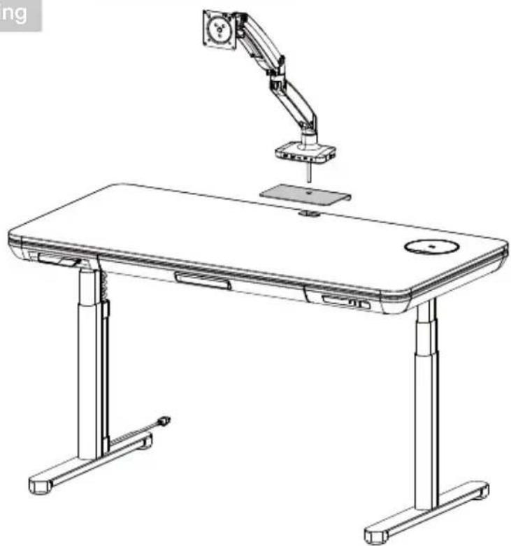
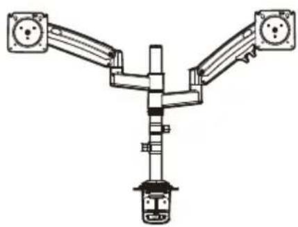
For the Galaxy Glass Standing Desk, we have also provided a Desktop Protector Pad. When you need to install a monitor stand on top of the desk, please refer to the illustration below to install the Desktop Protector Pad to prevent potential damaging that may occur during the installation process of a monitor stand.
For C-Clamp Mounting
natural_image
Line drawing of a modern office desk setup with two articulated arms mounted on top, no text or symbols present.For Grommet Mounting
natural_image
Line drawing of a desk setup with an adjustable arm and a baseplate, no text or symbols present.After placing the mobile phone on the wireless charging module, the module rises 60^ and rotates 30^ clockwise horizontally, and the mobile phone automatically detects charging. When the mobile phone is removed, the wireless charging module returns to its original position.
Light Sensing Area
When you wave your hand over this area, the light of the USB port will turn on.
C1 C2 A
Power Distribution of C1/C2/A Ports
Use Two Ports Use One Port Use Three Ports
C1/C2 Output: 100W Max
A Output: 22.5W Max
C1+C2 Output: 60W Max + 40W Max
C1+A Output: 80W Max + 18W Max
C2+A Output: 60W Max + 22.5W Max
C1+C2+A Output:
45W Max + 30W Max + 18W Max
Using the Control Panel
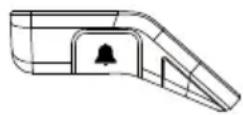
Sedentary Reminder Key (Left Key)

Controller
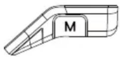
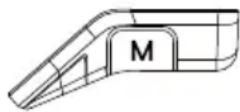
M Key
(Right Key)

NOTE: If you don't understand the introduction of the standing desk controller's functions, you can scan the QR code to download the APP. The APP can also control the standing desk, giving you a smarter experience. Before using this app on Samsung phones, you need to turn off the built-in Bixby.
- Low-Power Function
If there is no operation for 10 seconds, it will enter low-power mode, and the hand controller will display ERGOAV before turning off the screen and going to sleep.
- Memory Key Function
There are two presets for the memory function. One for heights greater than 35.5" and one for lower than 35.5". After setting the memory function, double push/pull on the control panel will adjust the table to either memory height 1 or 2.
Method of setting: Press the M button located on the right-hand side of the control panel, and ♥ -- - will appear. When the desk is above 35.5 inches, press and hold for M button 1 second, ♥ -- 1 will appear on the screen and the current position will be saved. When the desk is below or equal to 35.5 inches, press and hold for 1 second, ♥ -- 2 will appear on the screen and the current position will be saved.
- Sedentary Reminder Function
After setting the sedentary reminder time, press the button on the left side of the control panel to turn on or off the sedentary reminder function. The sedentary reminder function will not be timed when the desk height is above 39.3 inches. The sedentary reminder function will be timed when the desk height is 39.3 inches or below. After the sedentary time ends, the interface alternately displays (((△))) and ⚪ >>» at 1.5-second intervals. Prompting you to raise the desk to your desired height. The sedentary reminder function can also be set on the APP.
Method of setting: Press and hold the M key for 5 seconds. After ⬙ appears, enter the main menu. Toggle the control panel up or down to locate sedentary reminder function. After locating the sedentary reminder interface with 📋 press the M key to enter the corresponding submenu. Toggle the control panel up or down to set the sedentary reminder time. O confirming the sedentary reminder time, a confirmation icon √ will be displayed.
• Upper and Lower Limit Function
After setting the upper and lower limit function, when you pull the control panel up to reach the set upper limit, the desk will stop rising. When you push the control panel down to reach the set lower limit, the desk will stop descending once limit is reached.
Method of setting: Press and hold the M key for 5 seconds. Enter the main menu. Toggle the control panel to reach Upper and Lower Limit Function interface with ↓, press the M key to enter the corresponding submenu. Use the control panel to toggle up or down to the page.
Once on page, select the current position as the upper MAX or lower MIN height limit. After setting a height limit, if you want to adjust the desk to the other preferred limit, re-enter the menu and repeat the process.
• Control Panel Lock Function
The control panel lock function is designed to prevent accidental adjustments of the desk height through the control panel. Once the function is activated, the height of the standing desk cannot be adjusted through the control panel, but only through the APP. The control panel can be used again for adjustments after unlocking by following the steps below.
Method of setting: Press and hold the M button for 5 seconds to enter the main menu interface. Toggle the control panel up and down to display the control panel lock interface and press the M button to enter the corresponding submenu. Choose to turn on the control panel lock or turn it off.
When the control panel lock function is set successfully, the control panel will enter the lock mode after 10 seconds of inactivity. After pressing any button, the illustration ^ⓧ ^ⓨ ^ⓩ appears. Follow the button unlocking sequence in the illustration to return to the height display screen.
- Reset Function
After resetting the control pad any error message on the display screen will be cleared. Once reset, the desk will be at the highest position due to reset instructions and will not return to its original height unless manually done. All previous settings (memory positions, upper and lower limit, etc.) will not be reset.
Method of setting: When an error occurs, please refer to the attachment of the manual for troubleshooting (Error Code Solutions). Then press the control pad downwards for 5 seconds, until the screen displays ⏻. Once ⏻ is shown, the desk is in a reset state. Once in the reset state, release the control panel. After releasing it, press the control panel downwards again to start the reset. During the reset, the desk will rise to its highest position. After reaching the highest point, the reset is complete, and the screen will display the value of the desk's highest/current position.
Protection Mode Error Codes
| Abnormal Code | SolutionAbnormal Description | |
| E01 | M1 Over Current Protection | Check if the load is too heavy or if there is any object blocking the rise and lowering motion of the desk.If the issues from above mentioned are worked out, long-press the down button to reset, and after the reset is completed, continue using it. |
| E02 | M2 Over Current Protection | |
| E03 | M3 Over Current Protection | |
| E04 | M4 Over Current Protection | |
| E05 | M5 Over Current Protection | |
| E06 | M6 Over Current Protection | |
| E07 | M1 Hall Fault | Check if the legs are tightened, after eliminating the anomaly, long-press the down button to reset, and after the reset is completed, continue using it. |
| E08 | M2 Hall Fault | |
| E09 | M3 Hall Fault | |
| E10 | M4 Hall Fault | |
| E11 | M5 Hall Fault | |
| E12 | M6 Hall Fault | |
| E13 | Communication interruption between controller A and B. | Check if the connector between the A and B controllers is disconnected. After eliminating the anomaly, long-press the down button to reset, and after the reset is completed, continue using it. |
| The height difference between the two legs of the controller exceeds the set value and is not synchronized. | Check if the legs are tightened, after eliminating the anomaly, long-press the down button to reset, and after the reset is completed, continue using it. | |
| H01 | Overheat Protection(Work Mode Protection) | The controller needs to rest for a while. After the temperature drops, it can continue to be used. |

Remarque
natural_image
Line drawing of a rectangular electronic device with a circular button on top (no text or symbols)Bureau
01 x1
natural_image
Technical line drawing of a vertical cylindrical device mounted on a base (no text or symbols)Pied gauche
02 x1
natural_image
Simple line drawing of a cylindrical object mounted on a base with a small protrusion at the bottom (no text or symbols)Pied droit
03 x1
natural_image
Simple line drawing of a lever handle with no text or symbolsPieds
04 x2
Boulons M6 x 16
A x8
natural_image
Pure L-shaped metal angle line drawing without any text, numbers, or symbolsClé Allen
B x1
Étape 1
natural_image
Technical line drawing of a device casing with internal compartments and mounting points (no text or symbols)Étape 2
natural_image
Technical line drawing of a device chassis with internal components and two magnified insets showing connected connectors (no text or symbols)Étape 4
natural_image
Technical line drawing of a mechanical assembly with two vertical supports and mounting holes, showing no text or symbols.Étape 5
natural_image
Technical diagram of a mechanical assembly with rotating components and directional arrows, no text or symbols present

natural_image
3D rendering of a rectangular electronic device with a circular hole on top (no text or symbols)natural_image
Line drawing of a modern office desk setup with two robotic arms mounted on top (no text or symbols)natural_image
Line drawing of a desk setup with an arm-mounted device and a separate flatboard, no text or symbols present.natural_image
Simple line drawing of a smartphone on a circular base with a lightning bolt symbol, enclosed in a dashed circle (no text or labels)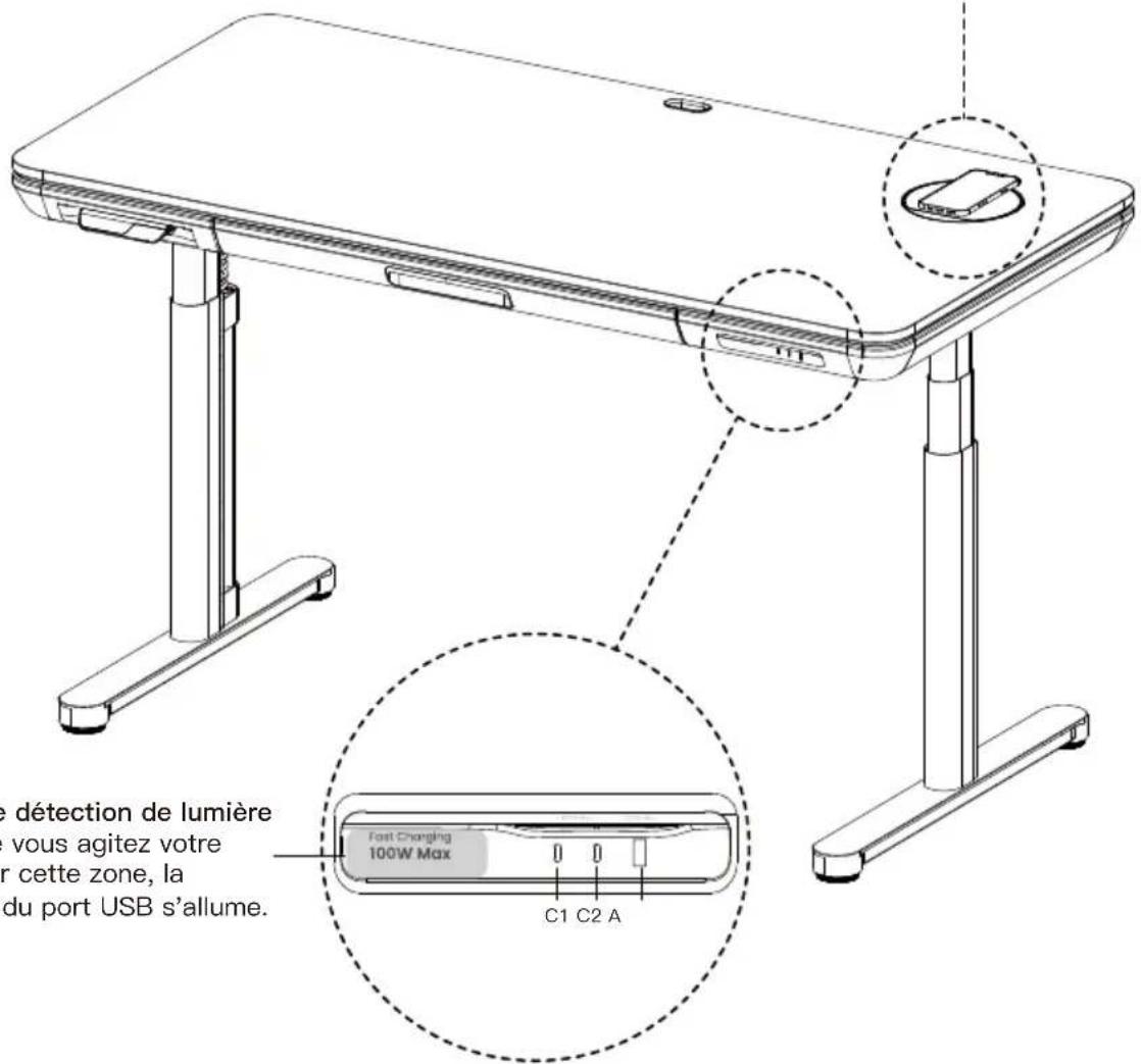
Touche M
(touche droite)
natural_image
Geometric diagram of a 3D shape resembling a prism with two petal-like cutouts (no text or symbols)natural_image
Geometric diagram of a 3D shape resembling a dog or prism (no text or symbols)natural_image
Line drawing of a rectangular electronic device with ports and a circular button (no text or symbols)Escritorio
01 x1
natural_image
Technical line drawing of a vertical cylindrical device with base and mounting base (no text or symbols)natural_image
Simple line drawing of a vertical cylindrical object mounted on a base with a small protrusion at the bottom (no text or symbols)Pata derecha
03 x1
natural_image
Simple line drawing of a horizontal bar with a small protrusion and dotted lines indicating measurement points (no text or symbols)Pies
04 x2
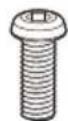
Pernos M6 x 16
A x8
natural_image
Simple L-shaped metal angle bracket diagram (no text or symbols)Llaven Allen
B x1
Paso 1
natural_image
Technical line drawing of a device's internal components, showing exploded and assembled views with no visible text or symbols.Paso 4
natural_image
Technical line drawing of a mechanical assembly with two vertical supports and mounting holes, showing no text or symbols.Paso 5
natural_image
Mechanical assembly diagram showing a frame with rotating shafts and mounting holes, no text or symbols present

natural_image
Simple 3D illustration of a rectangular object with a small circular hole at the top (no text or symbols)natural_image
Line drawing of a modern office desk setup with two robotic arms mounted on top (no text or symbols visible)Montaje con ojal

natural_image
Line drawing of a desk setup with an adjustable arm and a baseplate, no text or symbols present.natural_image
Simple line drawing of a smartphone on a circular base with a lightning bolt symbol, enclosed in a dashed circle (no text or labels)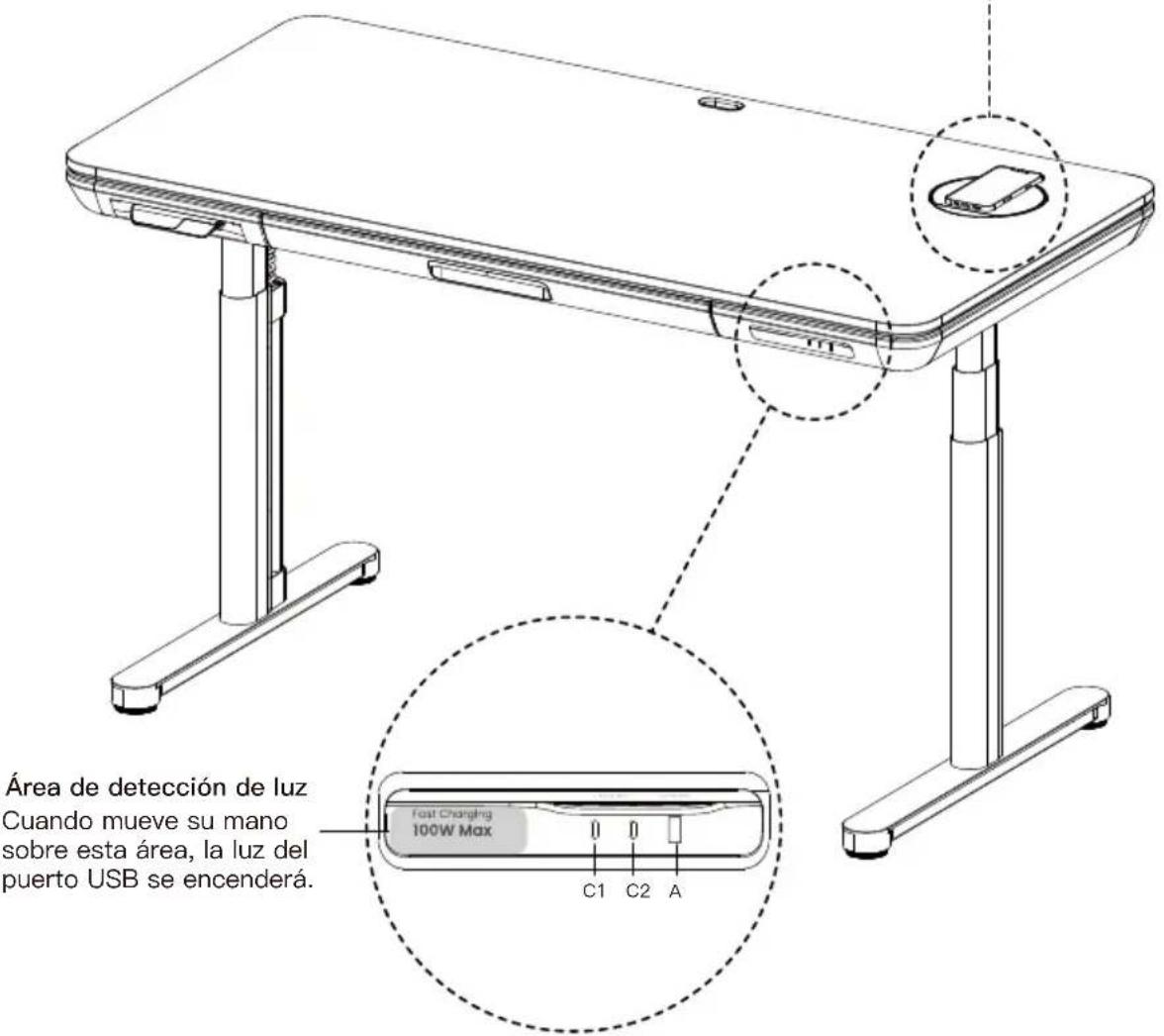
At ErgoAV, we strive to provide the highest value products. We want to support your purchase. If you have questions, concerns, or feedback please let us know!
ErgoAV Customer Care
Phone (877) 419-7832
support@ergoav.com
natural_image
Technical line drawing of a Y-shaped mechanical assembly with two mounting holes (no text or symbols)
natural_image
Technical line drawing of a mechanical assembly with mounting brackets and central housing (no text or symbols)
natural_image
Technical line drawing of a mechanical support structure with mounting feet (no text or symbols)TV MountsDesk Mounts Tabletop TV Stands
9501 Louisiana Ave N, #200, Brooklyn Park, MN 55445
www.ergoav.com
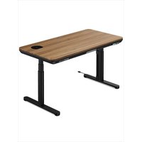
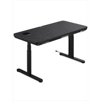
- Electric Standing Desk Instruction Manual
- Model: ERDS1-01G
- NOTE
- Important Safety Information
- Weight Restrictions
- WARNING
- Supplied Parts and Hardware
- Step 1
- Step 2
- Step 3
- Step 4
- Step 5
- Step 6
- CAUTION!
- Light Sensing Area
- Power Distribution of C1/C2/A Ports
- Use Two Ports Use One Port Use Three Ports
- Using the Control Panel
- - Low-Power Function
- - Memory Key Function
- - Sedentary Reminder Function
- • Upper and Lower Limit Function
- • Control Panel Lock Function
- - Reset Function
- Protection Mode Error Codes
- Remarque
- Étape 1
- Étape 2
- Étape 4
- Étape 5
- Paso 1
- Paso 4
- Paso 5
Brand : ErgoAV
Model : ERDS1-01G
Category : Office