BK-CD04E - Electric bike SHARP - Free user manual and instructions
Find the device manual for free BK-CD04E SHARP in PDF.

| Product type | Electric pedal-assist bike (EPAC) |
| Brand | Sharp |
| Model | BK-CD04E |
| Wheel size | 28 inches (700x40) |
| Total weight | 25 kg |
| Battery weight | 3 kg |
| Motor | 250 W, 36 V |
| Battery | Lithium, 36 V, 13 Ah |
| Range | 50 to 80 km |
| Charging time | 6 to 8 hours |
| Battery cycles | 500 cycles (≥70% capacity) |
| Charger | Input 100-240 V, output 36 V |
| Maximum assisted speed | 25 km/h |
| Maximum supported weight | 130 kg (rider + cargo + bike) |
| Recommended rider height | 165 to 190 cm |
| Brakes | Front and rear disc brakes |
| Transmission | Rear derailleur |
| Display | Multifunction LCD screen |
| Lighting | Front LED headlight, rear light |
| Rack | Max capacity 25-27 kg |
| Warranty | Frame and fork 2 years, electrical parts 2 years, battery 6 months (cells) / 24 months (electrical) |
| Maintenance | Service every 6 months recommended |
| Intended use | Urban and suburban, on paved roads |
Frequently Asked Questions - BK-CD04E SHARP
User questions about BK-CD04E SHARP
0 question about this device. Answer the ones you know or ask your own.
Ask a new question about this device
Download the instructions for your Electric bike in PDF format for free! Find your manual BK-CD04E - SHARP and take your electronic device back in hand. On this page are published all the documents necessary for the use of your device. BK-CD04E by SHARP.
USER MANUAL BK-CD04E SHARP
natural_image
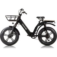
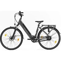
Black and white photo of a shared bicycles with a 'SHARP' branding, no visible text or symbols on the bike body.User Manual
BK-CD04E
Electric Bike
EN
FR
DE
PL
IT
FI
DA
SV

Translation of the original notice
The purpose of this manual is to give you the information necessary for the proper use, adjustment and maintenance of your bike.
Please take the time to read these instructions carefully before riding and keep them for the life of the bike. They contain important safety and maintenance instructions.
It is the user's responsibility to read this manual before using the product.
Failure to follow these instructions exposes you to the risk of improper use of your bike, premature wear of certain components which could lead to a fall and/or an accident.
In the event that an original part proves to be defective in workmanship within its warranty period, we promise to replace it. The warranty period for e-bikes is as follows:
frames and forks: 2 years
Electrical parts: 2 years with proper care and maintenance
All other components: 2 years with proper care and maintenance
As for the battery, it is guaranteed against manufacturing defects for 6 months on the pieces consumables ( cells ) and 24 months on pieces electrical , under reserve of respect of the instructions for use and storage indicated below:
√ Do not connect not the positive terminal directly to the terminal negative of this battery;
√ Do not place not battery in a high temperature place, in an exposed environment in or near the sun of fire;
√ Do not place not battery in a humid environment Or immersed in a liquid;
√ Do not disassemble not the battery pack without the guidance of a technician professional;
√ keep battery in a dry and temperate environment. Load battery all the month;
√ Please load this battery with charger exclusive accompanied by your bike.
√ Report your used battery at the house of your reseller.
This warranty does not include labor or transportation costs. The company assumes no liability for consequential or special damages. This warranty is applicable only to the original retail purchaser with proof of purchase validating any claim. This warranty is applicable only in case of defective parts and does not cover the effects of normal use, rental use, professional use, or damage caused by accidents, abuse, excessive loads, negligence, improper assembly, improper maintenance or addition objects inconsistent with normal use of the bicycle.
No bicycle is indestructible and no claim can be accepted for damage caused by improper use, rental use, professional use, use in competitions, stunts, ramp jumps, jumps or similar activities. Complaints must be made to the dealer. Your legal rights are not affected.
The company reserves the right to change or correct any details without notice. All information and details in this manual are correct at the time of printing.
He is forbidden to modify or tamper with the manual provided with the bike.
The bike is certified according to the standards of the law in force.
It is absolutely forbidden to change the parameters and specifications of the assembled electrical/mechanical components and standard functions of the motorcycle because this would compromise the proper operation of the vehicle and the safety of the user himself.
Should this happen, the user will be fully responsible for everything related to shaming.
Conditions of use of this electrically assisted bicycle
This electrically assisted bicycle is designed for urban and peri-urban use, it allows you to move around town, on the road or on a paved surface where the tires are always in contact with the ground. It is equipped with electric pedaling assistance which will make all your daily trips easier, to go further and for longer. Your electric bike is an adult bike, for people over 14 years old. In the event that the bicycle is used by a child, the responsibility is with the parents and must ensure that the user is able to use the bicycle safely.
Your bike is not intended for use on unpaved or rough terrain. It is not designed for "all-terrain" use, nor for competition. Failure to comply with this practice may result in a fall or accident and may prematurely and potentially irreversibly deteriorate the condition of your electric bike.
Your e-bike is not a moped. The purpose of the assistance is to provide a complement to the pedalling. The moment you start pedaling, the motor kicks in and helps you in the effort. The assistance varies according to the speed of the bike, high at start-up, less sustained when the bike is launched then disappears when the bike reaches 25 km/h. The assistance is cut off as soon as one of the two brake levers is actuated or the speed is greater than 25 km/h. This will resume automatically below 23 km/h with pedalling.
It must be properly maintained according to the instructions in this manual.

WARNING: Like any mechanical component, a bicycle is subject to high stress and wear. Different materials and components may react differently to wear or fatigue. If the expected lifespan of a component has been exceeded, it may break suddenly, risking injury to the cyclist. Cracks, scratches and discoloration in high stress areas indicate that the component has exceeded its life and should be replaced.
Recommendation: Safe and secure use
Before using your e-bike, make sure it is in good working order. Check the following points in particular:
- Position should be comfortable
• Nuts, screws, clamping levers, clamping components
• The brakes are in working order - The handlebar travel is good without too much play, the handlebar is correctly fixed to the stem
- Wheels are unobstructed and bearings are properly adjusted
• The wheels are properly tightened and attached to the frame/fork
• The tires are in good condition and their pressure is good.
• The condition of the rims
• The pedals are firmly attached to the crankset
• The operation of the transmission
• The reflectors are in the correct position.

RECOMMENDATION: Your electrically assisted bicycle must be serviced every 6 months by a professional to ensure that it is in good working order and safe to use. It is the user's responsibility to ensure that all components are in good working order before use.
Pick a safe place away from traffic to familiarize yourself with your new bike. The assistance can be triggered with force, check that your handlebars are straight and that the path is clear.
Make sure you are in good health before getting on your bike.
In the case of unusual weather conditions (rain, cold, night, etc.), be particularly vigilant and adapt your speed and reactions accordingly.
When transporting your bike outside your vehicle (bike carrier, roof rack, etc.), it is strongly recommended to remove the battery and store it in a temperate place.
The user must comply with the requirements of national regulations when the bicycle is used on public roads (lighting and signaling for example).

WARNING: You acknowledge that you are responsible for any loss, injury or damage caused by failure to follow the above instructions and that this will automatically void the warranty.

www.sharpconsumer.com/contact/

www.sharpconsumer.com/support/
www.sharpconsumer.com/documents-of-conformity/
Structure of power - assisted bicycles electric
BK-CD04E components
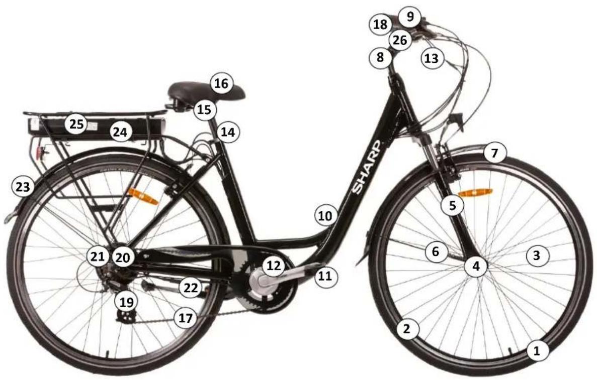
- Tyre and tube
- Wheel rim
- Spokes
- front hub, QR
- Fork
- front brake
- Front mudguard
- Stem and handlebar
- Bell
- Frame
- Pedals
- Crank arm and chain sets
-
Brake cables, gear cables, display cables
-
Seat lock
- Seat post
- Saddle
- Chain
- Display LCD
- Rear derailleur
- Hub motor
- Freewheel
- Kickstand
- Rear mudguard
- Rear carrier
- Battery
- Grips, shifter, brake levers
First start-up and settings
Installation of security elements
Lighting
Lighting is provided to you, it consists of two reflectors (a white one included in the front headlight and a red fixed on the rear mudguard), a front headlight, a rear light, reflectors positioned between the spokes of the wheels.
The lighting system is a safety feature of your bike, it must be present on your bike. Check that your lighting system is working properly before setting off.
Headlight
Front lighting is activated directly from the screen. See chapter "Display" on the following pages.
Taillight
lighting back is activated directly Since the screen. See "Display" chapter on the pages following.
doorbell
A bell is installed on your handlebars. It will allow you to be heard 50 m away.
The bell is a security feature of your bike, it must be present on your handlebars.
Wearing a helmet
For safe use, wearing a bicycle helmet is strongly recommended. It guarantees a reduction in head trauma in the event of a fall and augment the user safety.

WARNING: Wearing a helmet is compulsory for children under 14 as drivers or passengers.
For more information, ask your dealer.
Saddle and handlebar adjustment
It is important to adapt the settings of your bike to your morphology.
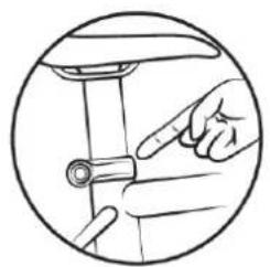
Saddle
Open the quick release system (see paragraph for the methodology for using the quick release).
When adjusting the saddle to its lowest position, make sure that it does not touch any component of the bicycle, such as the luggage rack. Likewise, take care not to exceed the minimum seat tube insertion mark. This insertion mark should never be visible when using the bike.
natural_image
Line drawing of a hand pointing at a mechanical component inside a circular frame (no text or symbols)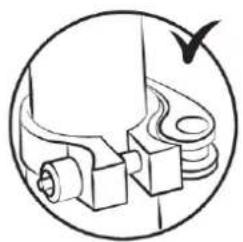
natural_image
Technical line drawing of a mechanical component with no visible text or symbols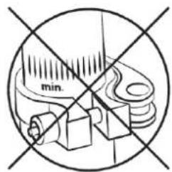
To check the correct saddle height, sit with your legs stretched out, heel resting on the pedal (fig. B). When pedalling, the knee will be slightly bent with the foot in the low position (fig. A).
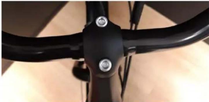
Handlebars
Your bicycle's handlebars can be adjusted up and down.
- Screw stem
Your bicycle is equipped with an “immersion” stem, and you can change the height by changing the insertion of the stem in the frame pivot tube.
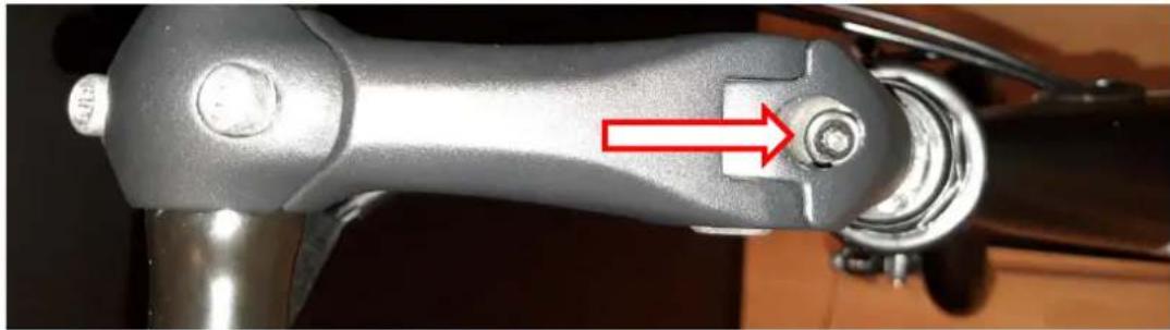
To adjust the height of the handlebar, loosen the clamping screw with a 6 mm hex wrench and raise or lower the stem to the desired height.
natural_image
Close-up of a mechanical lever handle with a red arrow pointing to a bolt (no text or symbols visible)Be careful not to exceed the minimum insertion mark. This insertion mark should never be visible when using the bicycle.
Tighten the immersion screw, making sure that the stem is in the correct position.
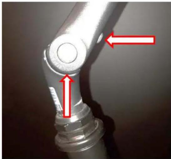
To adjust the tilt of the handlebar, loosen the stem screw-pivot shown in the picture below with a 5 mm hex key, select the position and tighten it.
natural_image
Close-up of a metallic robotic arm joint with red arrows indicating force or movement directions (no text or symbols present)You may then need to adjust the position of the handlebars on the stem by loosening the screws of the stem cover, turn the handlebars at your convenience and tighten these same screws. Take care that the handlebars are correctly centered.
natural_image
Close-up of a black bicycle seat with metal screws and a handle (no text or symbols visible)Tires
Check tire pressure regularly. Driving with under-inflated or over-inflated tires can affect performance, cause premature wear, reduce range or increase the risk of an accident.
If significant wear or a nick is visible on one of the tires, replace it before riding the bike. A pressure range is indicated on the sidewall of the tire by the manufacturer and in the following table. The pressure must be adapted according to the weight of the user.
| Pressure | |||||
| Model | Bike size | Air chamber size | Tire size | PSI | Bar |
| City | 28" | 700 x 40 | 700 x 40 | Check the value directly on the tyre | Check the value directly on the tyre |
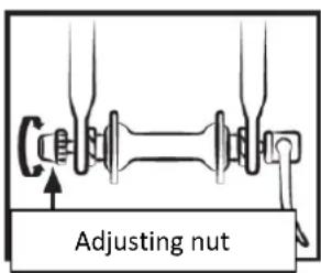
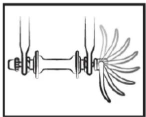
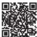
Method for determining correct adjustment of quick-release mechanisms (wheel and seat clamp)
Quick release devices are designed to be operated by hand. Never use tools to block or unblock the mechanism so as not to damage it.
To adjust the clamping force of the wheel axle, you must use the adjusting nut and not the quick release lever. If the lever can be moved with minimal hand pressure, it is not tight enough. It is therefore necessary to tighten the adjusting nut.
The quick-release system must mark the fork dropouts when closed in the locked position.
At each adjustment operation, check that the front wheel is correctly centered in relation to the fork. To adjust, close and open the quick-release mechanisms, apply the following method:
natural_image
Pure mechanical diagram showing a shaft and housing with multiple blades, no text or symbols present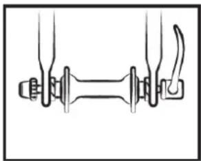
natural_image
Pure mechanical diagram showing two connected components with no text or symbols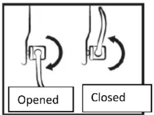
Adjusting the brakes
Before every use, check that the front and rear brakes are working perfectly.
The handle on the right activates the rear brake. The left handle activates the front brake.
It is recommended to distribute your braking force approximately 60/40 between the front and rear. The brake lever should not be in contact with the handlebars, and the sheaths should not be bent at right angles so that the cables can slide with a minimum of friction. Damages, fraying, rusty cables must be changed immediately.
WARNINGS:

- In case of rain or damp weather, braking distances are longer. It is recommended to anticipate braking in such a situation.
- If turning and braking, the handlebars can have a negative influence on the cyclist's response time.
- Do not touch the disc brakes after heavy use of your power-assisted bicycle's braking system as you may get burnt.
Brake adjustment
Before each use, check that the front and rear brakes are working properly.
The right handle activates the rear brake. The left handle activates the front brake.
It is recommended to distribute the braking force approximately 60/40 between the front and the rear. The brake lever must not come into contact with the handlebar and the sheaths must not
undergo closed angle trajectories, to ensure that the cables slide without the slightest friction. Damaged, frayed, rusty cables must be replaced immediately.
NB:

- In rainy or wet weather, braking distances become longer. It is recommended to brake earlier in these situations.
- When cornering and braking, the handlebars can have a negative influence on the rider's response time.
- Do not touch the disc brakes after intensive use of the pedal assisted bicycle's braking system, as you risk getting burned.
Adjusting the V-brakes
The pads exert a pressure directly on the wheel rims. The intensity of the pressure is controlled by a lever connected to the brake by a cable. Do not operate the brake lever when the wheel is detached from the frame.
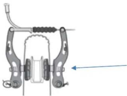
- Position the calliper arms vertically and parallel using the correct cable tension. Once the cable position has been defined, tighten the cable with the appropriate screw.
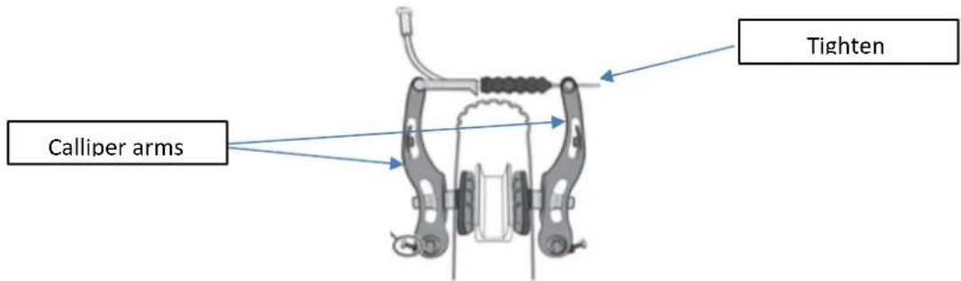
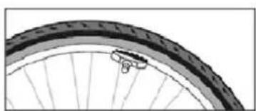
- Align the pad with the side of the wheel rim.
natural_image
Close-up of a bicycle wheel rim with visible tire and hub (no text or symbols)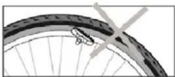
natural_image
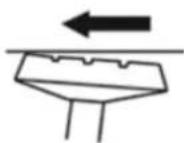
Close-up of a bicycle wheel rim with visible tire and spokes (no text or symbols)- Adjust the distance between the pads and the wheel rim, from 1 to 3 mm, to get better braking.
- Move the rear of the pad slightly away from the wheel rim.
ROLLING DIRECTION
- Adjust the calliper symmetry, balancing the return springs of the right and left callipers.
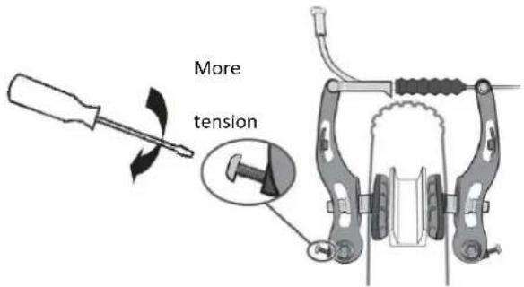
- A system consisting of a nut and a locking nut allows you to adjust the cable tension and therefore the braking power, which will vary with time as the brake pads wear down.
natural_image
Illustration of hands holding a tool with a screw-like component (no text or symbols)Changing the brake pads
- V-brake
natural_image
Mechanical bicycle clamp assembly diagram showing levers and suspension components (no text or labels)Unscrew the pads using a 5 mm hex key.
Place the new pads on the calliper in the right direction.
Tighten the pads, while respecting the setting.
Wear of the wheel rims
As any other part that is subject to wear, the wheel rim should be checked regularly. The wheel rim can weaken and break, causing you to lose control and fall.

WARNING: It is very important to check the wear of the wheel rims. If the marl becomes invisible with a V-brake, it means that the wheel rim has reached its maximum wear for safe use. A damaged wheel rim can be very dangerous and needs to b
replaced. Adjust the brake pads to maintain a spacing of 1 to 1.5 ~mm with the wheel rim.
Adjusting the gear changing system
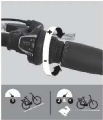
Your bicycle has several manually interchangeable speeds with a system with a rear derailleur. Use the right handle to make the desired change.
The higher the indicator, the more difficult it will be to pedal and vice versa.
Careful, never pedal backwards while changing gears and never force the command lever.
For an optimum use of the gear-changing system, we recommend avoiding changing gear other than during heavy pedalling sessions.
natural_image
Close-up of a bicycle brake lever mechanism with adjustment arrows and two labeled diagrams (① and ②) showing cycling positions.Adjusting the stops
The derailleur travel is adjusted using the H and L screws.
Screw L is used to adjust the upper stop (large gear side).
By loosening screw L, the chain is positioned further outside the large sprocket.
Screw H is used to adjust the lower stop (small pinion side).
By loosening screw H, the chain is positioned further outside the small sprocket.
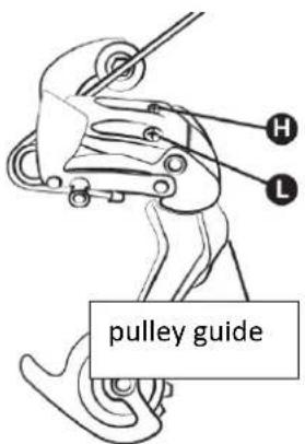
These manipulations are carried out by quarter turn. With each adjustment,
you must obtain perfect alignment between the sprocket, the chain and the pulley of the rear derailleur.
Cable tension adjustment
To set a correct sprocket change, use the knob present on the rear derailleur or the grip. This wheel allows you to adjust the tension of the derailleur cable and allows you to position the derailleur correctly according to the speed chosen.
Chain setting
Your bike is fitted with an external rear derailleur, the chain is automatically tensioned.
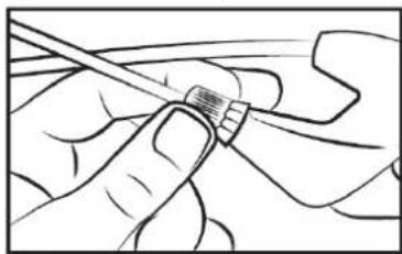
New chains are sold with too many links, the first step is to reduce it to the correct length. The safest method is to count the number of links in the old chain in order to adjust the new one. To disassemble the old chain, simply bypass it (remove a rivet).
Once it is removed, the new one must be mounted. To do this, it must be passed around the chainring of the crankset and the rear pinion so that it meshes correctly with the other elements of the transmission. To close the chain we recommend using a quick release. This acts as a female link that fits between two male links. Subsequently, the quick release will also make it easier to remove the chain for cleaning.
In order to check if the length of the chain is correct, it must be put on the small sprocket. In this configuration, the virtual line drawn between the hub of the rear wheel and the axle of the lower pulley of the derailleur must be vertical.
Change of pedals
To change your pedals, identify the pedals by looking at the letter noted on the pedal. The right pedal is marked “R” (Right) and the left pedal “L” (Left). Turn the “R” pedal clockwise to secure it to the crank. Turn the L pedal counterclockwise.
Wheel and motor
After the first month of use, it is advisable to tighten your spokes to limit the impact of engine traction on your rear wheel. When starting the engine, a slight noise may occur. This noise is normal because the motor starts and assists pedalling. This noise can become more prominent when fully loaded.
Luggage rack
The luggage rack is designed to support a maximum permitted weight of 25-27 kg; a child seat can be attached. Use an anchoring system suitable for this type of frame (not available as an accessory).

CAUTION: The roof rack is not designed to tow a trailer.
For safety, luggage should only be transported on the roof rack. Caution: When the pannier rack is loaded, the behaviour of the bike changes. Distribute the load of luggage evenly on both sides to
favour the stability of the bike. Any luggage must be securely attached to the pannier rack before using the bike. It is important to check that nothing is dangling or in danger of getting caught on the rear wheel of the bike. Do not modify the luggage carrier; any modification by the user renders these instructions null and void. Luggage must not obscure the bike's reflectors and lights.
Interview
Your bike requires regular maintenance for your safety but also to increase its lifespan. It is important to check the mechanical elements periodically in order to ensure, if necessary, replacement of worn parts or parts showing signs of wear.
When replacing components, it is important to use original parts in order to maintain the performance and reliability of the bicycle. Be sure to use appropriate spare parts for tyres, tubes, transmission components and the various components of the braking system.
It is the responsibility of the user to use parts different from the original parts.

WARNINGS: Always remove the battery before any maintenance operation.
Cleaning
In order to avoid corrosion of the bike, it is necessary to rinse your bike regularly with fresh water, especially if it has been exposed to sea air.
Cleaning must be done with a sponge, a basin of warm soapy water and a jet of water (no pressure).

RECOMMENDATION : Take special care not to use a high pressure water jet cleaner.
Lubrication
Lubrication is essential on the various components that are in motion in order to avoid corrosion. Oil the chain regularly, brush the sprockets and chainrings, periodically introduce a few drops of oil into the brake and derailleur cable sheaths.
It is advisable to start by cleaning and drying the elements to be lubricated.
It is advisable to use specific oil for the chain and the derailleur. Grease must be used for the other components.
Regular checks
Regarding the tightening of the bolts: lever, crank, pedals, stems.
The tightening torques to be applied are as follows:
| COMPONENTS | RECOMMENDED TORQUE (Nm) | SPECIFIC GUIDELINES |
| Pedals on crank arms | 30 - 40 | Lubricate the threads |
| Crank arm on bracket | 30 - 40 | Lubricate the threads |
| Stem/handlebar tightening | 9 - 10 | |
| Headset tightening | 14 - 15 | |
| Brake lever | 14 - 15 | Immersion screw (stem) |
| Brake callipers | 6 - 8 | |
| Seat | 6 - 8 | |
| Seat post clamp | 18 - 20 | |
| Wheel | 30 | Quick clamp |
Other tightening torques depend on the size of the nuts: M4: 2.5 to 4.0 Nm, M5: 4.0 to 6.0 Nm, M6: 6.0 to 7.5 Nm. Tighten the screws evenly to the required torque.
Regularly check the tires and in particular the condition of the rear tire teeth: wear, cuts, cracks, pinching. Replace the tire if necessary. Check the rims and the absence of excessive wear, deformations, blows, cracks...
Revisions
To ensure safety and keep components in good working condition, you should have your e-bike checked periodically by your dealer. In addition, maintenance of your bicycle should be carried out regularly by a qualified technician.
First service: 1 month or 150 km
- Verification of the tightening of the elements: crank, wheel, stem, pedals, handlebars, saddle clamp,
- Checking the operation of the electric assistance,
- Checking and adjusting the brakes,
- Wheel tension and/or runout.
Every year or 2000 km:
• Verification of wear levels (brake pads, transmission, tyres),
- Checking the operation of the electric assistance,
- Checking the bearings (bottom bracket, wheels, steering, pedals),
• Cable control (brakes, derailleur), - Lighting check,
- Wheel tension and/or runout.
Every 3 years or 6000 km:
- Changing the transmission (chain, freewheel, chainring),
- Checking the operation of the electric assistance,
- Changing tires,
- Wheel wear control (spokes, rim),
- Spoke tension and/or wheel trueing,
- Change of pads or brake pads,
• Control of electrical functions.
Pedal assistance and battery
The user must rotate the crank forward to benefit from the motorized assistance. This is an important safety aspect. This electric-assisted bicycle provides motorized assistance up to a speed of 25 km/h. Beyond that, the motor will stop. You can go faster, but you will have to do it on your own without power assistance.
The motor will not run until you turn the crankset one full turn. This feature protects the motor and its controller and extends the life of electrical components.
Pedal assist
To start the bike, turn on the main switch on the side of the ON/OFF battery
The rest of the settings and information are done directly on the display located on the handlebars.

Recommendation: Please turn off the main switch on the battery when you are no longer in the saddle. This saves battery charge.
Display LCD
The supplied display looks like this:
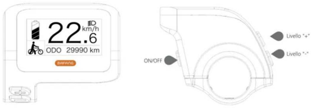
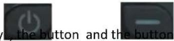
The LCD display has three buttons, the power/mode keys, the button and th

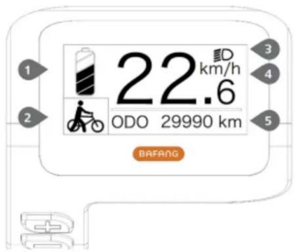
Battery charge level indication:
Indicates the current value of the charge level.
Assistance level indication:
Indicates the current level, from 0 to 5. If no number is displayed, it means there is no power; it means that the walk assist mode is active.
Front/rear lights on indication:
Only appears when the headlights or backlight are on.
Indicates the current speed measurement unit:
km/h or MPH
Multifunctional indication:
Includes single distance TRIP, total distance ODO, maximum speed MAX, average speed AVG, remaining distance RANGE, power output POWER, calories Cal, ride time TIME. (Note: After the display turns on, within ten seconds, if it detects the torque sensor signal or if it detects that it is the torque sensor, it will show the calories screen; if it detects the remaining distance, it will display the RANGE screen; or it will not display the two screens).
- Display on/off
Press and hold the power key, the display will start working. Press and hold the Power key again to turn off the device. When it is off, the display does not consume battery power because the leakage current is less than 1uA.
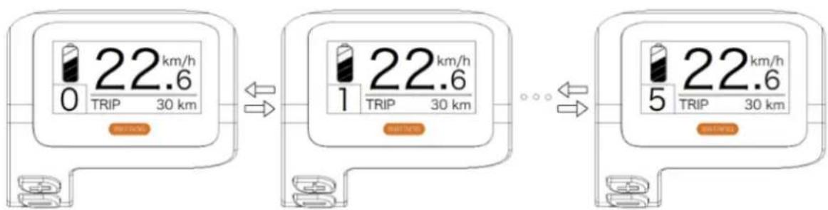
- Select the level of electric assistance
After starting, short press the plus or minus key to switch the level of assistance to change the motor output power. Level 0 means there is no electric assistance. Level 1 is the lowest level and level 5 is the highest level. After switching on the display, the default level is level 1.
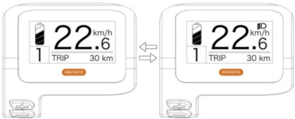
- Turning on the backlighting of the display, front and rear lights:
Turn on the light: Press and hold the "+" key to turn on the backlight of the display and headlights, the display will show the headlight icon. Turn off the light: Press and hold the "+" key again to turn off the backlight of the display and headlights, and the headlight icon will disappear.
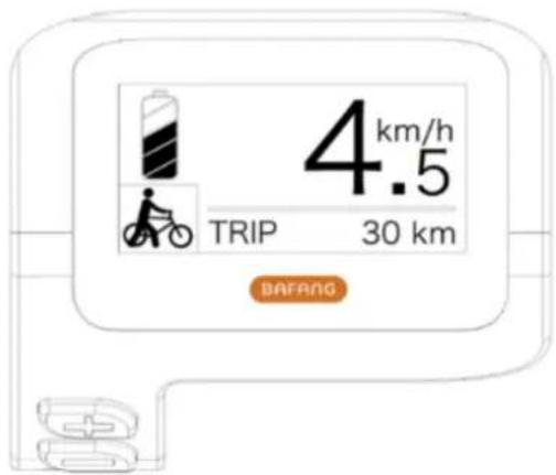
- The walk assist mode
Press and hold the "-" key, the display will show the icon and the bicycle will enter walking assist mode at the speed of 6km/h; release the "-" key, the icon will disappear from the display and the bicycle will end the walk assist mode.
• Functional indications of the different modes
The default menu is "TRIP" (single distance) and it can be switched alternately as "TRIP" (single distance) → "ODO" (total distance) → "MAX" (max speed) → "AVG" (average speed) → "RANGE" (remaining distance) → "CALORIES/CAL" (KCal) → "POWER" (output power) → "TIME" (travel time) → "TRIP" (single distance).
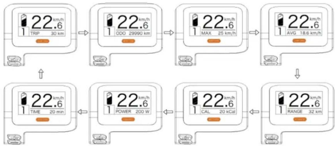
flowchart
graph TD
    A["1 TRIP 22.6 km/h 30 km"] --> B["1 ODO 22.6 km/h 29990 km"]
    B --> C["1 MAX 22.6 km/h 25 km/h"]
    C --> D["1 AVG 22.6 km/h 18.6 km/h"]
    D --> E["1 TIME 22.6 km/h 20 min"]
    E --> F["1 POWER 22.6 km/h 200 W"]
    F --> G["1 CAL 22.6 km/h 20 kCal"]
    G --> H["1 RANGE 22.6 km/h 32 km"]
• Indication of battery charge status
Shows the battery charge status in one to five lines. When it shows all five lines, it means the battery has full capacity. If the battery symbol flashes, it means that the battery needs to be charged immediately.
| Battery charge lines | State of charge | Diagram icon |
| 5 | 75%-100% | |
| 4 | 50%-75% | |
| 3 | 30%-50% | |
| 2 | 10%-30% | |
| 1 | 5%-10% | |
| LOW | LOW <5% | Flash |
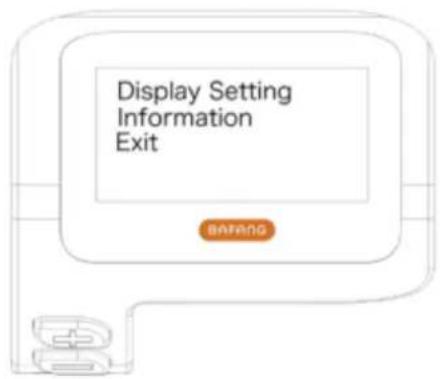
- FUNCTION SETTING
Press and hold the "+" & "-" keys simultaneously to enter the menu ("Display Setup", "Information", "EXIT").
Press "+" or "-" key to select "Display Setting", "Information" or "EXIT", then short press "power" key to confirm.
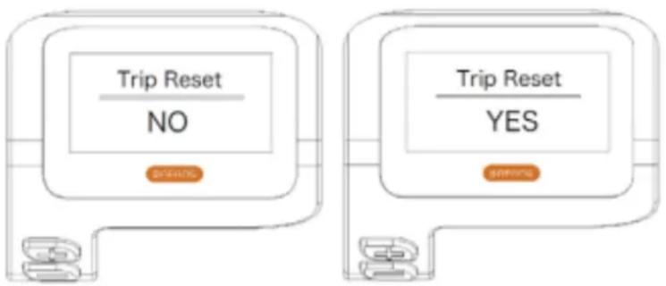
- Resets the mileage of a single journey
Enter the "Display Setting" menu and short press the "+" or "-" keys to select "TRIP Reset" and short press the "power" key.
Then, short press the "+" or "-" key to select "NO"/"YES" ("YES" means reset, "NO" means no reset).
Short press the "power" key to save the setting and return to the "TRIP Reset".
Press and hold "+" & "-" at the same time to save and return to the main screen or select "BACK"→"EXIT" to return to the main screen (note: after setting, press and hold the "+" and "-" at the same time means save the setting and return to the main screen).
When you reset the distance for a single trip, the trip time, average speed and maximum speed are also reset at the same time.
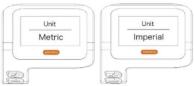
- Switching units of measure between Metric and Imperial
Enter the "Display Setting" menu and short press the "+" or "-" keys to select "Unit", then short press the "power" key to confirm.
Short press the "+" or "-" key to select "Metric" / "Imperial" and then short press the "power" key to save the setting and return to "Unit".
Press and hold the "+" & "-" keys simultaneously to exit the main screen or select "BACK"→"EXIT" to exit the main screen. (Note: If you select metric, all information will be metric; if you select imperial, all information will be imperial.)
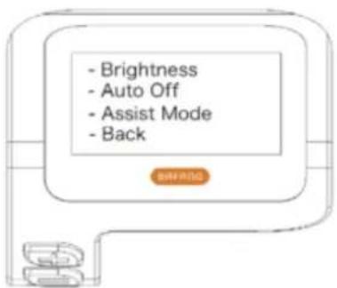
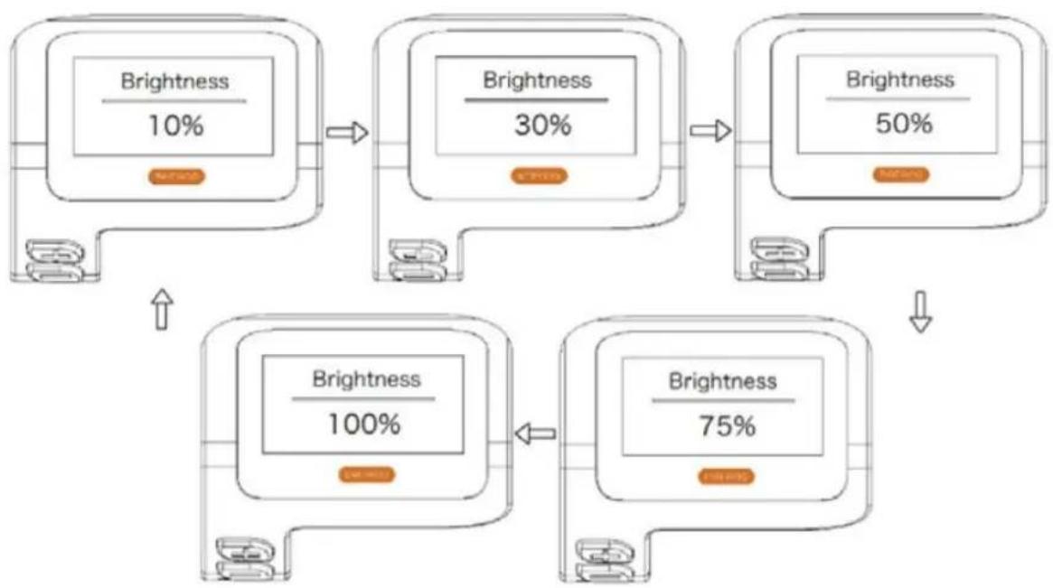
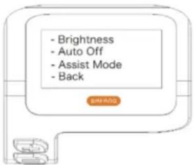
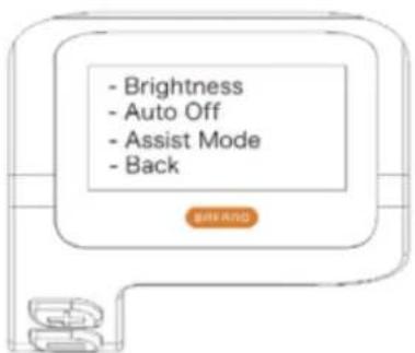
- Backlight setting
Enter the "Display Settings" screen and short press the "+" or "-" keys to select "Brightness", then short press the "power" key to confirm.
Short press the "+" or "-" key to select "100%"/"75%"/"50%"/"30%"/"10%".
After selection, short press the "power" button to save the setting and return to the "Brightness" screen.
Press and hold the "+" and "-" keys simultaneously to return to the main screen or select "BACK"→"EXIT" to return to the main screen.
flowchart
graph TD
    A["Brightness 10%"] --> B["Brightness 30%"]
    B --> C["Brightness 50%"]
    C --> D["Brightness 75%"]
    D --> E["Brightness 100%"]
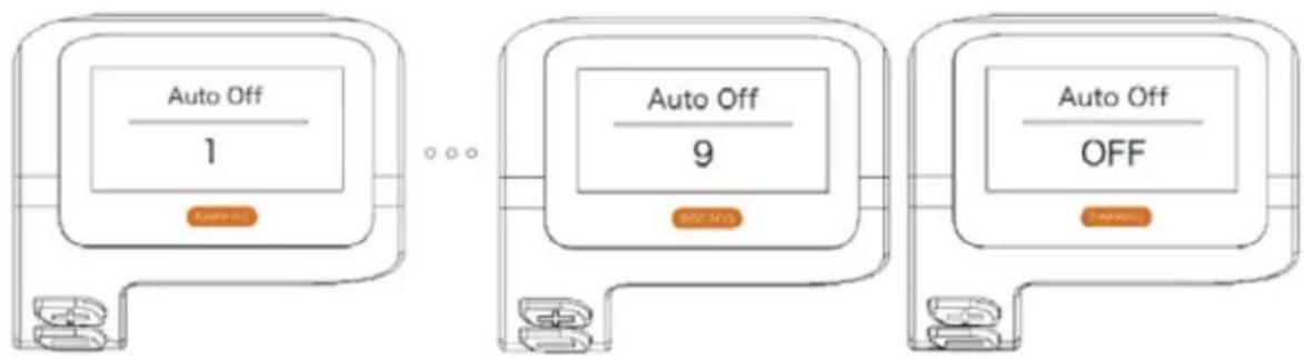
- Setting the "auto shut-off" time
Enter the "Display Settings" screen and short press the "+" or "-" keys to select "Auto Off", then short press the "power" key to confirm your choice. Short press "+" or "-" key to select "OFF"/"9"/"8"/"7"/"6"/"5"/"4"/"3"/"2"/"1".
After selection, short press the "power" button to save the setting and return to the "Auto Off" screen.
Press and hold the "+" and "-" keys simultaneously to return to the main screen or select "BACK"→"EXIT" to return to the main screen.
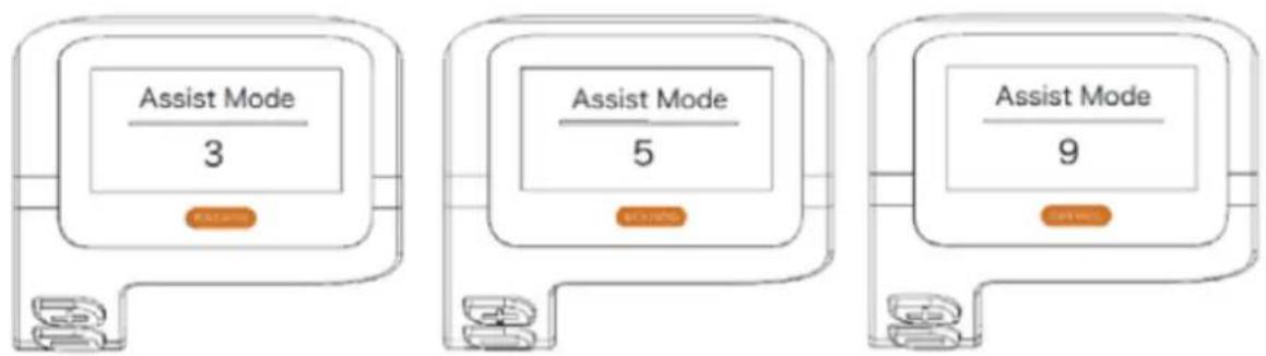
- Setting of electric assistance mode
Enter the "Display Setting" screen and short press the "+" or "-" keys to select "Assist Mode" and then short press the "power" key to confirm the setting. After setting, short press "+" or "-" to select "3"/"5"/"9" and then short press "power" key to save the setting and return to "Assist" mode. Press and hold the "+" and "-" keys to return to the main screen or select "BACK"→"EXIT" to return to the main screen.
The default level for viewing is level 5.
DEFINITION OF THE ERROR CODE
When a fault is detected, the icon is displayed. One of the following error codes will be displayed.
| Error code | Definition of error | Error resolution mode |
| "07" | High voltage protection | Check the tension of the battery |
| "08" | Hall sensor failure of the motor inside | Engine module check |
| "10" | The temperature of the controller reaches the maximum protection value | Check the controller |
| "12" | Faulty current sensor inside the regulator | Check the controller |
| "13" | Faulty temperature sensor inside the battery | Check the battery |
| "21" | Sensor detection failure wheel speed | Check the location of sensor installation speed |
| "22" | BMS communication fault | Replace the battery |
| "30" | Communication fault | Check the connection of the controllers |
Battery
Reading the level of charge on the battery
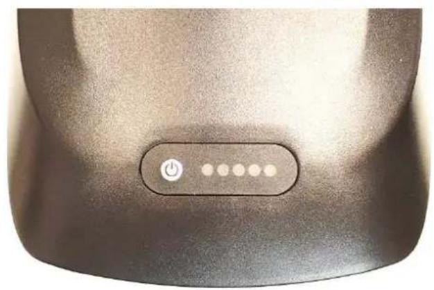
To find out your charge level, press the charge button located on the top of your battery once.
natural_image
Close-up of a black electronic device's power button with five dots, no visible text or symbolsThe 5 LEDs light up to indicate the level of charge and then go off after 4 seconds.
| DISPLAY | CHARGE LEVEL |
| ●●●●● | 100% |
| ●●●●○ | 80% |
| ●●●○○ | 60% |
| ●●○○○ | 40% |
| ●○○○○ | < 20% |
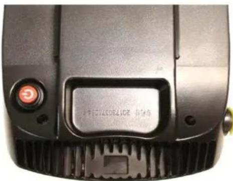
Switching the battery on / off
To turn on your battery, press the red ON/OFF button at the back on the bottom of the battery. Press it again to switch it off. When your battery is off it no longer provides power to your bicycle however the battery charge display remains functional.
natural_image
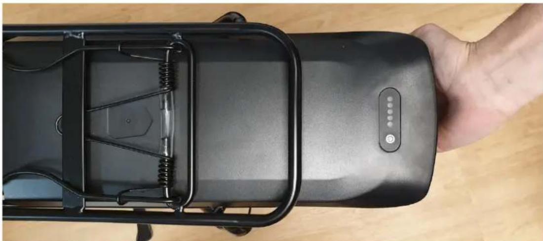
Close-up of a black industrial machine head with a circular button and ventilation grille (no visible text or symbols)Inserting / removing the battery
The battery on the power-assisted bicycles is placed on the rear rack, it is directly connected to the control box at the front.

WARNING: Before handling the battery, make sure the switch is in the off position.
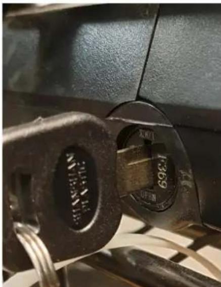
To install the battery, first slide the battery pack along the rail horizontally and press to make sure it is securely in place and lock.
natural_image
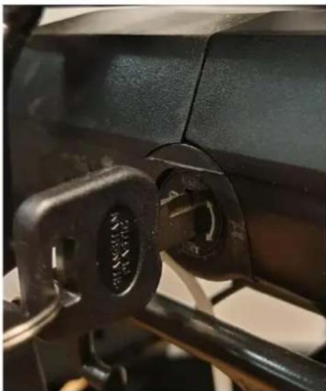
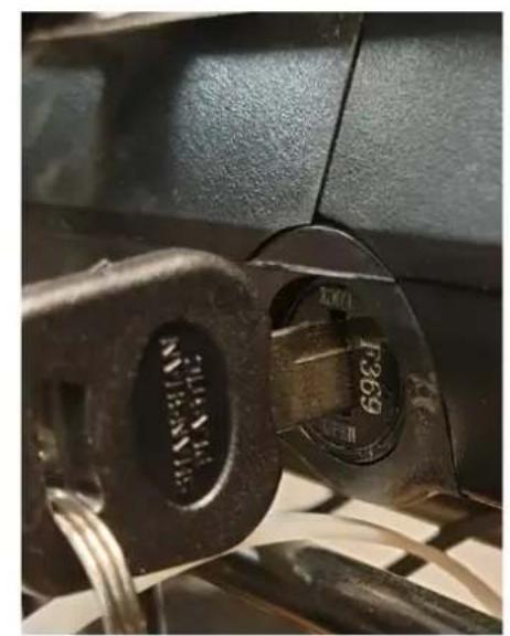
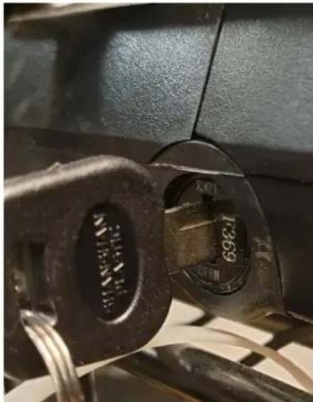
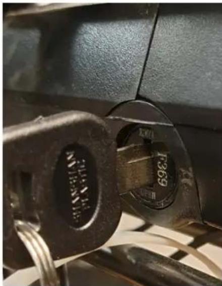
Top-down view of a hand holding an electric motor with visible internal components and a control panel (no text or symbols)To lock insert the key into the lock and turn it halfway clockwise (battery and luggage rack locked). You can unlock by turning halfway counter-clockwise.
natural_image
Close-up of a mechanical component with a black handle and circular opening, no visible text or symbolsLocked

natural_image
Close-up of a car's key and lever mechanism (no text or symbols visible)Unlocked

WARNING: Remember to remove the key and keep it safe after removing the battery from the rack!
Using the Charger
Before charging the battery, please read the user manual and the charger manual, if they came with your bike. Please also note the following points regarding the battery charger :
- Follow the instructions on the battery charger label.
- Do not use this charger near explosive gases or corrosive substances.
- Do not shake the charger, do not subject it to shocks and avoid falls.
• Always protect the charger from rain and humidity, for indoor use.
- The temperature tolerance of this charger is between 0 and +40°C.
- It is forbidden to disassemble the charger, in the event of a problem, entrust the device to a qualified repairer.
- You should only use the charger supplied with your e-bike to avoid damage. Note that failure to comply with this constraint will void the warranty.
- When recharging, the battery and charger should be at is 10cm away from the wall and in a dry and ventilated place. Do not place anything in direct proximity to the charger during use.
• Do not touch the charger for too long during charging (risk of superficial burns).
- Do not position the charger unstable.
- Do not cover the charger to avoid overheating while charging.
- Do not immerse the product
- Avoid contact with water while charging the battery. Do not touch the charger with wet hands.

- Do not use charger with damaged power cord or plugs. Make sure the charger plug is properly connected to the mains for charging.
- Do not short the charger pins using a metal object.
- Disconnect power before connecting or disconnecting battery connections.
- This charger is designed to charge Lithium batteries, do not charge the wrong type of battery. Do not use on a non-rechargeable battery.
- This device can be used by children aged of at under 8 years and by people having abilities reduced physical, sensory or mental Or devoid of experience or knowledge, if they (if they) are properly monitored or if instructions relating to the safe use of the device security their have summer data and if the risks incurred have summer apprehended. THE children should not play with the device. Cleaning and maintenance by the user must not be made by children without monitoring.
- It should be monitored THE children For make sure they don't play not with the device.
- Keep out of reach of children, this product is not a toy.
- The external flexible cable of this product cannot be replaced; in the event of damage to the cord, the product must be scrapped.
- At the end of its life, take the product to a recycling centre.

Recharge procedure
If a power outlet is available near your bike, you can charge the battery directly on the bike without detaching it. The charger socket is covered by a plastic cap, you just need to open it to charge the battery directly.
Removing the battery can be useful in places that cannot accommodate your bike or when it is not near a power outlet.

RECOMMENDATION: Charging the battery should be done indoors in a ventilated area.
Please charge the bicycle battery according to the following procedure:
- The battery can be recharged using a standard power outlet. It is not necessary to activate its switch.
- Insert the charger plug into the battery and plug the charger power cable into a nearby outlet.
- When charging, the LED on the charger will be red to indicate proper operation. When it turns green, it means the battery is charged.
- To finish charging, you must disconnect the power plug, then the plug connected to the battery. Finally close the battery socket cap.
This e-bike is equipped with a high quality Li-ion battery. Li-ion batteries have memory-free charging and a wide temperature tolerance range of -10 to +40°C.
To ensure maximum battery life and to protect it from damage, please follow the use and care instructions below.
Battery life
After charging your battery, it is advisable to let it rest for 20 to 30 minutes before use.
Your battery life depends on several usage factors:
• The choice of assistance mode
- User's weight
• The elevation of the road
- Tire inflation
- The wind
• The pedaling effort provided
- Starting and frequency of stops
• The outside temperature
Warning, precautions
It is recommended to recharge the batteries on a regular basis, or after each use. There is no memory effect on these batteries. In order to maximize the life of your battery, it is recommended:
- Avoid hot places (ideal charging temperature 20^ )
- Let the battery cool down 30 minutes after using the bike
Precautions for use:
- Use the battery only for this bike.
- Only use the specific charger delivered to charge the battery.
- Only charge the battery in a well-ventilated area.
- Do not expose the battery to heat or charge it in direct sunlight.
- Do not disassemble or modify the case and the battery which is integrated in the case.
- Do not connect the (+) and (-) connections of the battery with a metal object.
- Do not expose the battery to liquids.
- Do not use a damaged battery.
- Do not continue to charge the battery if the charge is not complete after the theoretical charge time.
- Do not use the battery if it emits an unusual odor, heats up unusually, or if anything appears abnormal.
- Do not leave the battery within the reach of children.
- Recharge your battery before prolonged storage and carry out the same operation after this storage.

Battery life
Batteries can suffer from performance aging after a large number of charges.
This will depend on the usage habits of the pedelec.
You must drop off your used batteries at your store or at specialized recycling drop-off points. Above all, do not throw your battery at the end of its life into the environment.
Battery maintenance
To ensure maximum battery life and to protect it from damage, please follow these use and care instructions:
When you notice that the charge drops to 10%, the battery needs to be recharged quickly.

RECOMMENDATION: If the bike is not used frequently over a period of time, it should be fully charged every month. The battery case should be stored in a dry, protected place at a temperature between 5 and 35°C.
WARNING:

- Battery life may be reduced by prolonged storage without regular recharging as mentioned above.
- Do not use any metal to directly connect two poles of the battery, which may cause a short circuit.
- Never place the battery near a fireplace or any other heat source.
- Do not shake the battery, subject it to shock or drop it.
- When the battery pack is removed from the bike, keep it out of the reach of children to avoid accidents.
- It is forbidden to open the battery.
Use and maintenance of the electric motor
Our e-bikes are programmed to start the e-assist after half a turn of the pedal.
Do not use the bike in flooded places or during thunderstorms. Do not immerse electrical components in water to avoid damage.
Avoid knocks on the engine to avoid damaging it.
Controller Maintenance
It is very important to take good care of the controller according to the following instructions:
- Protect the controller from water ingress and submersion.
Note: If you suspect water may have entered the case, please turn off the battery immediately and continue without assistance. You can restart it as soon as the controller is dry.
- Do not shake the controller, do not subject it to shock and avoid dropping.

WARNING: Do not open the controller enclosure. Any attempt to open the controller enclosure, modify it or adjust it will void the warranty. Please ask your dealer or qualified professional to carry out repairs.
Any modification of the parameters of the electric management system, in particular the change of the speed limit, is strictly prohibited and will invalidate the guarantee of your bike.
Main data sheet
| Maximum weight: User + Charge + bicycle | 130 kg | |
| Maximum speed with assistance | 25 km/h | |
| Autonomy | Approx. 50 to 80 km | |
| Motorisation | Max power | 250 W |
| Voltage | 36V | |
| Maximum noise during use | < 70 dB | |
| Battery | Type | Lithium |
| Voltage | 36V | |
| Capacity | 13 Ah | |
| Weight | 3 kg | |
| Charging time | 6-8 h | |
| Number of cycles (≥70% capacity) | 500 cycles | |
| Charger | Input voltage | 100-240V |
| Output voltage | 36V | |
| Total weight of the bicycle | 25 kg | |
| Dimensions of the bicycle | 28” | |
| Size tyres / wheel | 700 x 40 | |
| User size | 165 - 190 | |
After- sales
Wear part
The different wear elements are standard elements. Always replace worn parts and/or parts to be changed with identical components sold on the market or from your dealer.
Basic troubleshooting
Do not attempt to access or repair any electrical component yourself. Contact the specialist closest to you for maintenance by a qualified person.
The information below is for explanatory purposes and not instructions to assist the user in repairs. Any troubleshooting procedure mentioned should be performed by a qualified professional who is aware of safety issues and familiar with electrical maintenance.
| Description of the problem | Possible causes | Resolution |
| After the battery is turned on, the motor does not assist pedaling. | 1) the motor cable (waterproof connection joint) is connected incorrectly2) the brake lever did not properly return to the normal position, forcing the switch off3) the battery fuse is blown4) the speed sensor is too far from the magnetic disk on the BB axis5) The connection between the sensor and the controller is not established or has a bad contact. | First, check that the battery is charged.If not, reload it.1) check that the connection is well established, without any play2) return the brake lever to its normal position carefully without braking3) Open the top of the battery pack and check the condition of the fuse. If blown, contact your authorized retailer or professional for a replacement.4) Adjust the distance between the sensor and the magnetic strip to be no more than 3mm5) Make sure the controller and sensor are well connected. |
| Battery life shortens(note: battery performance is directly influenced by the weight of the user, luggage, wind strength, type of road, constant braking). | 1) the reload time is not enough2) the ambient temperature is too low and influences the battery operation3) frequent hills or headwinds as well as poor road conditions4) the tire pressure is not sufficient (re-inflate them)5) frequent shutdowns and restarts6) the battery has been stored without recharging for a long time. | 1) please recharge the battery following the instructions (chapter 7.3)2) In winter or temperature below 0°C, your battery should be kept indoors3) This is a normal cause and the problem will resolve as conditions improve4) inflate the tires to a pressure of 3.1 bar5) The problem will resolve with the improvement of usage situations6) Carry out regular recharging in accordance with the instruction manual. If this does not solve the problem, contact your dealer or qualified professional. |
| After plugging in the charger, the charging LEDs do not light up. | 1) problem with the electrical outlet2) poor contact between the charger input socket and the electrical outlet3) the temperature is too low. | 1) inspect and repair electrical outlet2) inspect and insert the plug fully3) Charge indoors.If the above solutions have no effect, contact your dealer or qualified professional. |
| After charging for more than 4/5 hours, the charging indicator LED is still red( note : it is very important to recharge the battery following the instructions to avoid damaging the equipment). | 1) ambient temperature is 40°C or more2) ambient temperature is 0°C or less3) the bike was not recharged after use which exaggerated the unloading4) the output voltage is too low to be able to recharge the battery. | 1) Charge the battery under temperature below 40°C and in accordance with the instructions2) recharge the battery indoors and in accordance with the instructions3) Properly maintain the battery to avoid over-discharging4) Do not perform recharging with voltage lower than 100V.If the above solutions have no effect, contact your dealer or qualified professional. |
| LCD display:The speed is not displayed on the LCD screen. | The magnetic ball on the spoke of the wheel is too far from the sensor (attached to the rear of the frame or to the front fork) which prevents the sensor from receiving the signal when the wheel is spinning. | Check the distance between the magnetic ball and the sensor and make sure it does not exceed 5mm . |
Troubleshoot charger issues:
- The Red light does not work during charging: check that the connectors are correctly connected. Check if the normal voltage is passed at once, if so, please check the charger repair. If the above is correct, the battery is definitely faulty.
- Red light does not turn green: turn off the power, after 5 seconds then connect the AC power, it can continue to charge. The battery can no longer be charged, the battery is definitely defective.
- The Red light immediately turns green: check that the battery is fully charged. If not, the battery or charger is faulty.

www.sharpconsumer.com/support/

www.sharpconsumer.com/documents-of-conformity/
natural_image
Close-up of a mechanical lever handle with a red arrow pointing to a bolt (no text or symbols visible)natural_image
Close-up of a metallic robotic arm joint with red arrows indicating force or movement (no text or symbols)natural_image
Close-up of a black bicycle wheel with metal fasteners and screws, mounted on a wooden surface (no text or symbols visible)
natural_image
Close-up of a bicycle wheel rim and wheel, showing tire and spokes (no text or symbols)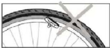
natural_image
Close-up of a bicycle wheel rim with visible tire and wheel (no text or symbols)natural_image
Line drawing of hands holding a tool with a screw-like component (no text or symbols)natural_image
Mechanical bicycle clamp assembly diagram showing levers and suspension components (no text or labels)natural_image
Close-up of a bicycle steering wheel with adjustment rings and control buttons, showing two bicycle icons below (no text or symbols on the diagram itself)Réglage des butées
flowchart
graph TD
    A["Brightness 10%"] --> B["Brightness 30%"]
    B --> C["Brightness 50%"]
    C --> D["Brightness 100%"]
    D --> E["Brightness 75%"]
natural_image
Close-up of a black textured surface with a small circular button labeled (a) and three evenly spaced dots on the right side (no text or symbols beyond the button)natural_image
Close-up of a black industrial machine component with a circular indicator light and ventilation grille (no visible text or symbols)natural_image
Top-down view of a hand holding a black electronic device with a handle and control panel (no visible text or symbols)natural_image
Close-up of a black mechanical component with a circular hole and metal bracket (no visible text or symbols)Bloqués
natural_image
Close-up of a car's key being inserted into a circular opening, showing the number 1369 and 'ALL-LENS' on its keys (no text beyond labels)Débloqué


www.sharpconsumer.com/support/
www.sharpconsumer.com/documents-of-conformity/
natural_image
Line drawing of a hand pointing at a mechanical component inside a circular frame (no text or symbols)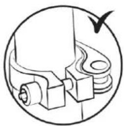
natural_image
Diagram of a mechanical component with a bird flying around it, no text or symbols present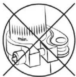
natural_image
Illustration of a person performing a high kick exercise, showing two stages (A and B) with no text or symbols present.Lenker
natural_image
Close-up of a mechanical lever handle with a red arrow pointing to a bolt (no text or symbols visible)natural_image
Close-up of a robotic arm joint with red arrows indicating force or movement directions (no text or symbols present)natural_image
Close-up of a bicycle seat with red arrows pointing to key points (no text or symbols visible)Reifen
natural_image
Pure diagram of a mechanical or fluidic device with no text, numbers, or symbols
natural_image
Pure mechanical diagram showing a shaft and clamping mechanism without any text or symbols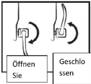
flowchart
graph TD
    A["Öffnen Sie"] --> B["Geschlossen"]
    B --> C["Arrow to Left"]
    B --> D["Arrow to Right"]
Bremse
natural_image
Two-panel illustration showing bicycle wheel rim and bicycle wheel with a cross mark (no text or symbols)natural_image
Diagram showing a screwdriver operating a tool to switch a mechanical component, with a magnified inset highlighting the mechanism (no text or symbols present)natural_image
Mechanical linkage diagram showing two articulated arms with springs and a central connector (no text or symbols)natural_image
Close-up of a bicycle switch mechanism with directional arrows and two labeled diagrams (1, 2) showing cycling positions.flowchart
graph TD
    A["Brightness 10%"] --> B["Brightness 30%"]
    B --> C["Brightness 50%"]
    C --> D["Brightness 75%"]
    D --> E["Brightness 100%"]
    E --> F["Downward arrow"]
natural_image
Close-up of a black electronic device's power button with five dots, no visible text or symbols| ANZEIGE | LADEZUSTAND |
| ● ● ● ● ● | 100% |
| ● ● ● ● ○ | 80% |
| ● ● ● ○ ○ | 60% |
| ● ● ○ ○ ○ | 40% |
| ● ○ ○ ○ ○ | < 20% |
natural_image
Close-up of a black industrial machine component with a circular indicator light and a button labeled '201703715-4' (no readable text beyond label)natural_image
Top-down view of a hand holding a black electronic device with visible internal components and a control panel (no text or symbols)natural_image
Close-up of a black mechanical component with a circular opening and metal bracket (no visible text or symbols)Blockiert

natural_image
Close-up of a mechanical switch with two keys, one labeled 'T369' and the other showing a number 1704 (no additional text or symbols visible)Ungesperrt


www.sharpconsumer.com/contact/

www.sharpconsumer.com/support/
www.sharpconsumer.com/documents-of-conformity/
natural_image
Illustration of a person performing a bicycle leg lift exercise, labeled A and B (no text or symbols on the diagram itself)Manubrio
natural_image
Close-up of a mechanical lever handle with a red arrow pointing to a bolt (no text or symbols visible)natural_image
Close-up of a metallic robotic arm joint with red arrows indicating force or movement directions (no text or symbols present)natural_image
Close-up of a black bicycle wheel with metal fasteners and mounting brackets (no text or symbols visible)Pneumatici
natural_image
Pure diagram of a mechanical or electrical component with no text, numbers, or symbols
natural_image
Pure mechanical diagram showing two connected components with no text or symbols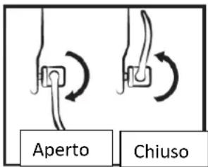
natural_image
Close-up of a bicycle wheel rim and wheel rim with visible tire, no text or symbols present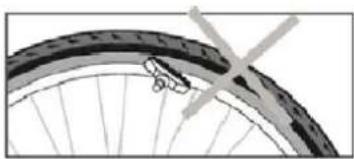
natural_image
Close-up of a bicycle wheel rim with visible tire and spokes (no text or symbols)natural_image
Illustration of a hand holding a pen or tool, no text or symbols presentnatural_image
Mechanical diagram of a bicycle clutch assembly with no visible text or symbolsnatural_image
Close-up of a bicycle brake lever mechanism with adjustment arrows and two labeled diagrams (① and ②) showing cycling motion.
flowchart
graph TD
    A["Brightness 10%"] --> B["Brightness 30%"]
    B --> C["Brightness 50%"]
    C --> D["Brightness 100%"]
    D --> E["Brightness 75%"]
DEFINIZIONE DEL CODICE DI ERRORE
natural_image
Close-up of a black electronic device's power button with five dots, no visible text or symbols| DISPLAY | LIVELLO DI CARICA |
| ● ● ● ● ● | 100% |
| ● ● ● ● ◇ | 80% |
| ● ● ● ◇ ◇ | 60% |
| ● ● ◇ ◇ ◇ | 40% |
| ● ◇ ◇ ◇ ◇ | < 20% |
natural_image
Close-up of a black industrial device with a circular button and ventilation grille (no visible text or symbols)natural_image
Top-down view of a hand holding a black electric motor with visible internal components and a control panel (no text or symbols)natural_image
Close-up of a mechanical component with a black handle and metal bracket (no visible text or symbols)Bloccato
natural_image
Close-up of two black keys with engraved numbers, partially visible against a dark background (no readable text or symbols)Sbloccato


www.sharpconsumer.com/contact/

www.sharpconsumer.com/support/

www.sharpconsumer.com/documents-of-conformity/
natural_image
Illustration of a person performing a high kick exercise, showing two sequential stages (A and B) with no text or symbols.Hantle
natural_image
Close-up of a mechanical lever handle with a red arrow pointing to a bolt (no text or symbols visible)natural_image
Close-up of a robotic arm joint with red arrows indicating force or movement (no text or symbols present)natural_image
Close-up of a black bicycle wheel with metal fasteners and mounting brackets (no text or symbols visible)Opony
natural_image
Diagram of a mechanical device with multiple blades radiating outward (no text or symbols)
natural_image
Pure mechanical diagram showing two connected components with no text or symbols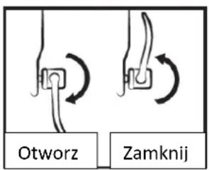
natural_image
Close-up of a bicycle wheel rim with visible tire and hub (no text or symbols)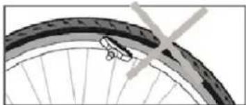
natural_image
Close-up of a bicycle wheel rim with visible tire and spokes (no text or symbols)natural_image
Illustration of a hand holding a pen or tool, no text or symbols presentnatural_image
Mechanical diagram of a bicycle clamp assembly with no visible text or symbolsnatural_image
Close-up of a bicycle steering wheel with adjustment rings and two circular icons below (no text or symbols)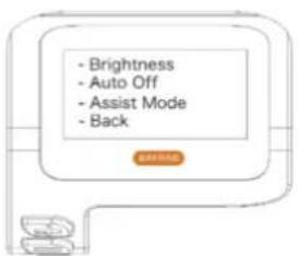
flowchart
graph TD
    A["Brightness 10%"] --> B["Brightness 30%"]
    B --> C["Brightness 50%"]
    C --> D["Brightness 75%"]
    D --> E["Brightness 100%"]
DEFINIOWANIE KODU BŁĘDU
natural_image
Close-up of a black ergonomic device with a power button and five dots on the side (no text or symbols visible)| WYŚWIETLAĆ | POZIOM NAŁADOWANIA |
| ● ● ● ● ● | 100% |
| ● ● ● ● ○ | 80% |
| ● ● ● ○ ○ | 60% |
| ● ● ○ ○ ○ | 40% |
| ● ○ ○ ○ ○ | < 20% |
natural_image
Close-up of a black industrial device with a circular indicator light and ventilation grille (no visible text or symbols)natural_image
Top-down view of a hand holding a black electronic device with visible internal components and a small illuminated button (no text or symbols)natural_image
Close-up of a mechanical component with a black handle and circular opening, no visible text or symbolsZablokowany

natural_image
Close-up of a mechanical switch with visible latches and metal hardware (no text or symbols)Odblokowany


www.sharpconsumer.com/contact/

www.sharpconsumer.com/support/

www.sharpconsumer.com/documents-of-conformity/
natural_image
Close-up of a mechanical lever handle with a red arrow pointing to a bolt (no text or symbols visible)natural_image
Close-up of a metallic robotic arm joint with red arrows indicating force or movement (no text or symbols)natural_image
Close-up of a black bicycle wheel hub with metal fasteners (no text or symbols visible)Dæk
natural_image
Pure diagram of a mechanical or electrical component with no text, numbers, or symbols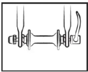
natural_image
Pure mechanical diagram showing a shaft and connecting rod (no text or symbols)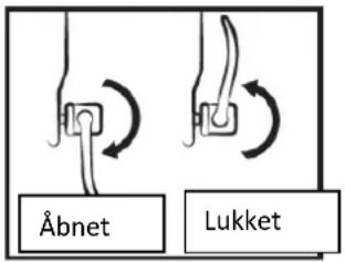
natural_image
Close-up of a bicycle wheel rim with visible tire and hub (no text or symbols)
natural_image
Close-up of a bicycle wheel rim with visible tire and wheel (no text or symbols)natural_image
Illustration of hands holding a tool with a screwdriver, no text or symbols presentnatural_image
Mechanical diagram of a bicycle clamp mechanism with no visible text or symbolsnatural_image
Close-up of a bicycle steering wheel with adjustment rings and control buttons (no text or symbols visible)Justering af stop

flowchart
graph TD
    A["Brightness 10%"] --> B["Brightness 30%"]
    B --> C["Brightness 50%"]
    C --> D["Brightness 75%"]
    D --> E["Brightness 100%"]
    E --> F["Downward arrow"]
DEFINITION AF FEJLKODEN
natural_image
Close-up of a button with a power indicator and five dots arranged on a surface (no text or symbols visible)| VISE | OPLADNINGSNIVEAU |
| ● ● ● ● ● | 100% |
| ● ● ● ● ○ | 80% |
| ● ● ● ○ ○ | 60% |
| ● ● ○ ○ ○ | 40% |
| ● ○ ○ ○ ○ | < 20% |
natural_image
Close-up of a black industrial machine component with a circular indicator light and a label showing '201703712-4' (no readable text beyond label)natural_image
Top-down view of a hand holding a black electronic device with visible wires and a control panel (no text or symbols)natural_image
Close-up of a mechanical component with a black handle and circular opening, no visible text or symbolsBlokeret
natural_image
Close-up of a car's key dial with 'T369' marking, showing mechanical components and wiring (no readable text beyond label)Ulåst


www.sharpconsumer.com/support/

www.sharpconsumer.com/documents-of-conformity/
natural_image
Close-up of a mechanical lever handle with a red arrow pointing to a bolt (no text or symbols visible)natural_image
Close-up of a robotic arm joint with red arrows indicating force or movement directions (no text or symbols present)natural_image
Close-up of a black bicycle wheel with metal fasteners and mounting screws (no text or symbols visible)Renkaat
natural_image
Pure mechanical diagram showing a shaft and housing with multiple blades, no text or symbols present
natural_image
Pure mechanical diagram showing two connected components with no text or symbols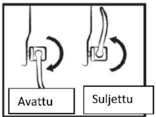
natural_image
Close-up of a bicycle wheel rim and wheel, showing tread pattern and central hub (no text or symbols)
natural_image
Close-up of a bicycle wheel rim with visible tire and hub (no text or symbols)natural_image
Illustration of a hand holding a pen or tool, no text or symbols presentnatural_image
Mechanical bicycle clamp assembly diagram showing levers and suspension components (no text or labels)natural_image
Close-up of a bicycle cable connector with adjustment rings and two circular icons below (no text or symbols)Pysäyttimien säätö
• Taustavalon asetus
flowchart
graph TD
    A["Brightness 10%"] --> B["Brightness 30%"]
    B --> C["Brightness 50%"]
    C --> D["Brightness 75%"]
    D --> E["Brightness 100%"]
VIRHEKOODIN MÄÄRITELMÄ
natural_image
Close-up of a black electronic device's power button with five dots, no visible text or symbols| NÄYTTÖ | LATAUSTASO |
| ● ● ● ● ● | 100% |
| ● ● ● ● ○ | 80% |
| ● ● ● ○ ○ | 60% |
| ● ● ○ ○ ○ | 40% |
| ● ○ ○ ○ ○ | < 20 % |
natural_image
Close-up of a black industrial machine component with a circular indicator light and ventilation grille (no readable text or symbols)natural_image
Top-down view of a hand holding a black electronic device with a handle and internal components (no visible text or symbols)natural_image
Close-up of a mechanical component with a black handle and circular opening, no visible text or symbolsTukossa

natural_image
Close-up of a car's key dial with 'T369' marking, showing mechanical components and wiring (no readable text beyond label)Auki


www.sharpconsumer.com/contact/

www.sharpconsumer.com/support/
www.sharpconsumer.com/documents-of-conformity/
natural_image
Line drawing of a hand pointing at a mechanical component inside a circular frame (no text or symbols)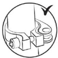
natural_image
Pure mechanical component diagram without any text, numbers, or symbols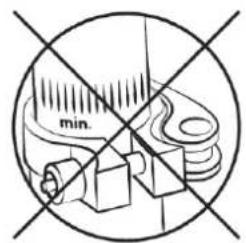
natural_image
Close-up of a mechanical lever handle with a red arrow pointing to a bolt (no text or symbols visible)natural_image
Close-up of a metallic robotic arm joint with red arrows indicating force or movement (no text or symbols)natural_image
Close-up of a black bicycle seat with metal bolts and a wooden handle (no text or symbols visible)Däck
natural_image
Close-up of a bicycle wheel rim with visible tire and hub (no text or symbols)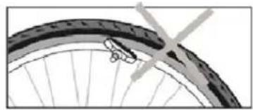
natural_image
Close-up of a bicycle wheel rim with visible tire and spokes (no text or symbols)natural_image
Line drawing of a hand holding a pen or tool, no text or symbols presentnatural_image
Mechanical clamp device with attached cable and spring (no text or symbols)natural_image
Close-up of a bicycle brake lever mechanism with adjustment arrows and two circular icons below (no text or symbols)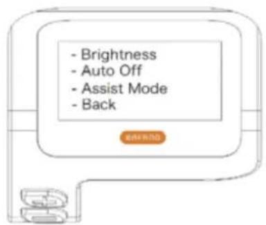
flowchart
graph TD
    A["Brightness 10%"] --> B["Brightness 30%"]
    B --> C["Brightness 50%"]
    C --> D["Brightness 100%"]
    D --> E["Brightness 75%"]
DEFINITION AV FELKODEN
natural_image
Close-up of a black electronic device's power button with five dots, no visible text or symbols| VISA | LADDNINGSNIVÅ |
| ● ● ● ● ● | 100% |
| ● ● ● ● ○ | 80% |
| ● ● ● ○ ○ | 60% |
| ● ● ○ ○ ○ | 40% |
| ● ○ ○ ○ ○ | < 20 % |
Slå på/av batteriet
natural_image
Close-up of a black industrial device with a circular indicator light and a small label on its side (no readable text or symbols)natural_image
Top-down view of a hand holding a black electric motor with visible internal components and a control panel (no text or symbols)natural_image
Close-up of a black mechanical component with a circular opening, showing no visible text or symbols.Blockerad
natural_image
Close-up of a car's key and lever mechanism (no visible text or symbols)Olåst

Sharp Consumer Electronics Poland sp. z o.o.
Ostaszewo 57B, 87-148 Łysomice, Poland
www.sharpconsumer.eu
SHARP