
DCG404 - Electric grinder DEWALT - Free user manual and instructions
Find the device manual for free DCG404 DEWALT in PDF.

User questions about DCG404 DEWALT
0 question about this device. Answer the ones you know or ask your own.
Ask a new question about this device
Download the instructions for your Electric grinder in PDF format for free! Find your manual DCG404 - DEWALT and take your electronic device back in hand. On this page are published all the documents necessary for the use of your device. DCG404 by DEWALT.
USER MANUAL DCG404 DEWALT
English (original instructions) 31
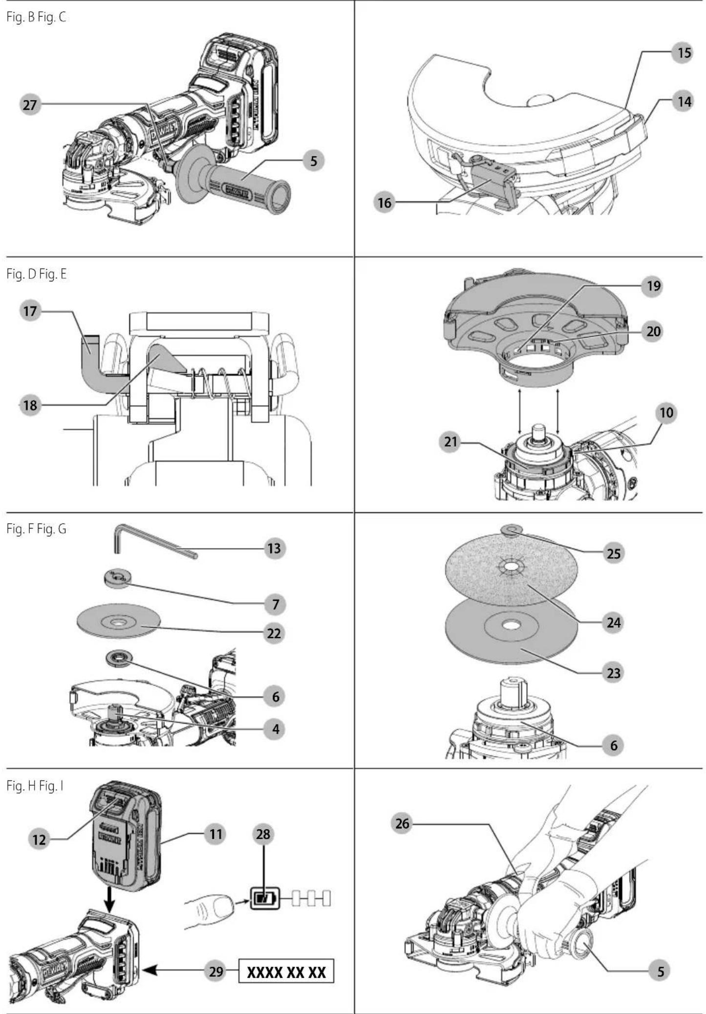
Fig. J
natural_image
Technical diagram of a mechanical component with labeled parts (no readable text or symbols)Fig. K
natural_image
Technical line drawing of a mechanical assembly with an arrow indicating motion direction (no text or symbols)Fig. L
natural_image
Technical line drawing showing two mechanical assembly diagrams with no text or symbolsLILLE VINKELSLIBER
DCG404
natural_image
Illustration of two mechanical components with circular holes, no text or symbols presentnatural_image
Illustration of stacked books and a hand with crossed-out gears, enclosed in a circular frame (no text or symbols)SMALL ANGLE GRINDER
DCG404
Documents Available Online
www.2helpU.com/DoC/ or www.2helpU.com/DoC/index/xxx*
*For direct access, replace "xxx" with the product's model number given on the product rating label or packaging.
- Instruction Manual
• Declaration of Conformity (DoC) - Product Emission Data (PED): Information about Noise, Vibration and Dust (not applicable for all products)

WARNING: Read all safety warnings, instructions, illustrations, and specifications in this manual, including the battery and charger sections provided in an original tool manual or the separate Batteries and Chargers manual. Manuals can be obtained by contacting
Customer Service (refer to the back page of this manual).
Technical Data
| DCG404 | ||
| Voltage V | _DC | 18 |
| Type 1 | ||
| Battery type Li-Ion | ||
| No load speed min | ^-1 | 11000 |
| Grinding wheel diameter mm 125 | ||
| Grinding wheel thickness (max) mm 6.4 | ||
| Cutting off wheel diameter mm 125 | ||
| Cutting off wheel thickness (max) mm 3 | ||
| Wire wheel diameter mm 125 | ||
| Wire wheel thickness (max) mm 11 | ||
| Spindle diameter | M14 | |
| Spindle length | mm | 21.5 |
| Weight (without battery pack; with Type B guard, flange, auxiliary handle) | kg | 1.56 |

WARNING: To reduce the risk of injury, read the instruction manual.
Definitions: Safety Guidelines
The definitions below describe the level of severity for each signal word. Please read the manual and pay attention to these symbols.
RANGER: Indicates an imminently hazardous situation which, if not avoided, will result in death or serious injury.
WARNING: Indicates a potentially hazardous situation which, if not avoided, could result in death or serious injury.
AUTION: Indicates a potentially hazardous situation which, if not avoided, may result in minor or moderate injury.
NOTICE: Indicates a practice not related to personal injury which, if not avoided, may result in property damage.
▲ denotes risk of electric shock.
A denotes risk of fire.

GENERAL POWER TOOL SAFETY WARNINGS
WARNING: Read all safety warnings, instructions, illustrations and specifications provided with this power tool. Failure to follow all instructions listed below may result in electric shock, fire and/or serious injury.
SAVE ALL WARNINGS AND INSTRUCTIONS FOR FUTURE REFERENCE
The term "power tool" in the warnings refers to your mains-operated (corded) power tool or battery-operated (cordless) power tool.
Work Area Safety
a) Keep work area clean and well lit. Cluttered or dark areas invite accidents.
b) Do not operate power tools in explosive atmospheres, such as in the presence of flammable liquids, gases or dust. Power tools create sparks which may ignite the dust or fumes.
c) Keep children and bystanders away while operating a power tool. Distractions can cause you to lose control.
Electrical Safety
a) Power tool plugs must match the outlet. Never modify the plug in any way. Do not use any adapter plugs with earthed (grounded) power tools. Unmodified plugs and matching outlets will reduce risk of electric shock.
b) Avoid body contact with earthed or grounded surfaces, such as pipes, radiators, ranges and refrigerators. There is an increased risk of electric shock if your body is earthed or grounded.
c) Do not expose power tools to rain or wet conditions. Water entering a power tool will increase the risk of electric shock.
d) Do not abuse the cord. Never use the cord for carrying, pulling or unplugging the power tool. Keep cord away from heat, oil, sharp edges or moving parts. Damaged or entangled cords increase the risk of electric shock.
e) When operating a power tool outdoors, use an extension cord suitable for outdoor use. Use of a cord suitable for outdoor use reduces the risk of electric shock.
f) If operating a power tool in a damp location is unavoidable, use a residual current device (RCD) protected supply. Use of an RCD reduces the risk of electric shock.
Personal Safety
a) Stay alert, watch what you are doing and use common sense when operating a power tool. Do not use a power tool while you are tired or under the influence of drugs, alcohol or medication. A moment of inattention while operating power tools may result in serious personal injury.
b) Use personal protective equipment. Always wear eye protection. Protective equipment such as a dust mask, non-skid safety shoes, hard hat or hearing protection used for appropriate conditions will reduce personal injuries.
c) Prevent unintentional starting. Ensure the switch is in the off position before connecting to power source and/or battery pack, picking up or carrying the tool. Carrying power tools with your finger on the switch or energising power tools that have the switch on invites accidents.
d) Remove any adjusting key or wrench before turning the power tool on. A wrench or a key left attached to a rotating part of the power tool may result in personal injury.
e) Do not overreach. Keep proper footing and balance at all times. This enables better control of the power tool in unexpected situations.
f) Dress properly. Do not wear loose clothing or jewellery. Keep your hair and clothing away from moving parts. Loose clothes, jewellery or long hair can be caught in moving parts.
g) If devices are provided for the connection of dust extraction and collection facilities, ensure these are connected and properly used. Use of dust collection can reduce dust-related hazards.
h) Do not let familiarity gained from frequent use of tools allow you to become complacent and ignore tool safety principles. A careless action can cause severe injury within a fraction of a second.
Power Tool Use and Care
a) Do not force the power tool. Use the correct power tool for your application. The correct power tool will do the job better and safer at the rate for which it was designed.
b) Do not use the power tool if the switch does not turn it on and off. Any power tool that cannot be controlled with the switch is dangerous and must be repaired.
c) Disconnect the plug from the power source and/or remove the battery pack, if detachable, from the power tool before making any adjustments, changing accessories, or storing power tools. Such preventive safety measures reduce the risk of starting the power tool accidentally.
d) Store idle power tools out of the reach of children and do not allow persons unfamiliar with the power tool or these instructions to operate the power tool. Power tools are dangerous in the hands of untrained users.
e) Maintain power tools and accessories. Check for misalignment or binding of moving parts, breakage of parts and any other condition that may affect the power tool's operation. If damaged, have the power tool repaired before use. Many accidents are caused by poorly maintained power tools.
f) Keep cutting tools sharp and clean. Properly maintained cutting tools with sharp cutting edges are less likely to bind and are easier to control.
g) Use the power tool, accessories and tool bits, etc. in accordance with these instructions, taking into account the working conditions and the work to be performed. Use of the power tool for operations different from those intended could result in a hazardous situation.
h) Keep handles and grasping surfaces dry, clean and free from oil and grease. Slippery handles and grasping surfaces do not allow for safe handling and control of the tool in unexpected situations.
Battery Tool Use and Care
a) Recharge only with the charger specified by the manufacturer. A charger that is suitable for one type of battery pack may create a risk of fire when used with another battery pack.
b) Use power tools only with specifically designated battery packs. Use of any other battery packs may create a risk of injury and fire.
c) When battery pack is not in use, keep it away from other metal objects, like paper clips, coins, keys, nails, screws or other small metal objects, that can make a connection from one terminal to another. Shorting the battery terminals together may cause burns or a fire.
d) Under abusive conditions, liquid may be ejected from the battery; avoid contact. If contact accidentally occurs, flush with water. If liquid contacts eyes, additionally seek medical help. Liquid ejected from the battery may cause irritation or burns.
e) Do not use a battery pack or tool that is damaged or modified. Damaged or modified batteries may exhibit unpredictable behaviour resulting in fire, explosion or risk of injury.
f) Do not expose a battery pack or tool to fire or excessive temperature. Exposure to fire or temperature above 130 °C may cause explosion.
g) Follow all charging instructions and do not charge the battery pack or tool outside the temperature range specified in the instructions. Charging improperly or at temperatures outside the specified range may damage the battery and increase the risk of fire.
Service
a) Have your power tool serviced by a qualified repair person using only identical replacement parts. This will ensure that the safety of the power tool is maintained.
b) Never service damaged battery packs. Service of battery packs should only be performed by the manufacturer or authorised service providers.
ADDITIONAL SPECIFIC SAFETY RULES
Safety Warnings Common for Grinding, Sanding, Wire Brushing, or Cutting-Off Operations
a) This power tool is intended to function as a grinder, sander, wire brush, or cut-off tool. Read all safety warnings, instructions, illustrations and specifications provided with this power tool. Failure to follow all instructions listed below may result in electric shock, fire and/or serious injury.
b) Operations such as polishing and hole cutting are not to be performed with this power tool. Operations for which the power tool was not designed may create a hazard and cause personal injury.
c) Do not convert this power tool to operate in a way which is not specifically designed and specified by the tool manufacturer. Such a conversion may result in a loss of control and cause serious personal injury
d) Do not use accessories which are not specifically designed and specified by the tool manufacturer. Just because the accessory can be attached to your power tool, it does not assure safe operation.
e) The rated speed of the accessory must be at least equal to the maximum speed marked on the power tool.
Accessories running faster than their rated speed can break and fly apart.
f) The outside diameter and the thickness of your accessory must be within the capacity rating of your power tool. Incorrectly sized accessories cannot be adequately guarded or controlled.
g) The dimensions of the accessory mounting must fit the dimensions of the mounting hardware of the power tool. Accessories that do not match the mounting hardware of the power tool will run out of balance, vibrate excessively and may cause loss of control.
h) Do not use a damaged accessory. Before each use inspect the accessory such as abrasive wheels for chips and cracks, backing pad for cracks, tear or excess wear, wire
brush for loose or cracked wires. If power tool or accessory is dropped, inspect for damage or install an undamaged accessory. After inspecting and installing an accessory, position yourself and bystanders away from the plane of the rotating accessory and run the power tool at maximum no-load speed for one minute. Damaged accessories will normally break apart during this test time.
i) Wear personal protective equipment. Depending on application, use face shield, safety goggles or safety glasses. As appropriate, wear dust mask, hearing protectors, gloves and workshop apron capable of stopping small abrasive or workpiece fragments. The eye protection must be capable of stopping flying debris generated by various operations. The dust mask or respirator must be capable of filtrating particles generated by the particular operation. Prolonged exposure to high intensity noise may cause hearing loss.
j) Keep bystanders a safe distance away from work area. Anyone entering the work area must wear personal protective equipment. Fragments of workpiece or of a broken accessory may fly away and cause injury beyond immediate area of operation.
k) Hold the power tool by insulated gripping surfaces only, when performing an operation where the cutting accessory may contact hidden wiring. Contact with a "live" wire will also make exposed metal parts of the power tool "live" and could give the operator an electric shock.
1) Never lay the power tool down until the accessory has come to a complete stop. The spinning accessory may grab the surface and pull the power tool out of your control.
m) Do not run the power tool while carrying it at your side. Accidental contact with the spinning accessory could snag your clothing, pulling the accessory into your body.
n) Regularly clean the power tool's air vents. The motor's fan will draw the dust inside the housing and excessive accumulation of powdered metal may cause electrical hazards.
o) Do not operate the power tool near flammable materials. Sparks could ignite these materials.
p) Do not use accessories that require liquid coolants. Using water or other liquid coolants may result in electrocution or shock.
FURTHER SAFETY INSTRUCTIONS FOR ALL OPERATIONS
Kickback and Related Warnings
Kickback is a sudden reaction to a pinched or snagged rotating wheel, backing pad, brush or any other accessory. Pinching or snagging causes rapid stalling of the rotating accessory which in turn causes the uncontrolled power tool to be forced in the direction opposite of the accessory's rotation at the point of the binding.
For example, if an abrasive wheel is snagged or pinched by the workpiece, the edge of the wheel that is entering into the pinch point can dig into the surface of the material causing the wheel to climb out or kick out. The wheel may either jump toward or away from the operator, depending on direction of the wheel's movement at the point of pinching. Abrasive wheels may also break under these conditions.
Kickback is the result of tool misuse and/or incorrect operating procedures or conditions and can be avoided by taking proper precautions as given below:
a) Maintain a firm grip with both hands on the power tool and position your body and arms to allow you to resist
kickback forces. Always use auxiliary handle, if provided, for maximum control over kickback or torque reaction during start up. The operator can control torque reaction or kickback forces, if proper precautions are taken.
b) Never place your hand near the rotating accessory. Accessory may kickback over your hand.
c) Do not position your body in the area where power tool will move if kickback occurs. Kickback will propel the tool in direction opposite to the wheel's movement at the point of snagging.
d) Use special care when working corners, sharp edges etc. Avoid bouncing and snagging the accessory. Corners, sharp edges or bouncing have a tendency to snag the rotating accessory and cause loss of control or kickback.
e) Do not attach a saw chain woodcarving blade, segmented diamond wheel with a peripheral gap greater than 10 mm or toothed saw blade. Such blades create frequent kickback and loss of control.
Safety Warnings Specific for Grinding and Cutting-Off Operations
a) Use only wheel types that are specified for your power tool and the specific guard designed for the selected wheel. Wheels for which the power tool was not designed cannot be adequately guarded and are unsafe.
b) The grinding surface of centre depressed wheels must be mounted below the plane of the guard lip. An improperly mounted wheel that projects through the plane of the guard lip cannot be adequately protected.
c) The guard must be securely attached to the power tool and positioned for maximum safety, so the least amount of wheel is exposed towards the operator. The guard helps to protect the operator from broken wheel fragments, accidental contact with wheel and sparks that could ignite clothing.
d) Wheels must be used only for specified applications. For example: do not grind with the side of cut-off wheel. Abrasive cut-off wheels are intended for peripheral grinding, side forces applied to these wheels may cause them to shatter.
e) Always use undamaged wheel flanges that are of correct size and shape for your selected wheel. Proper wheel flanges support the wheel thus reducing the possibility of wheel breakage. Flanges for cut-off wheels may be different from grinding wheel flanges.
f) Do not use worn down wheels from larger power tools. A wheel intended for larger power tool is not suitable for the higher speed of a smaller tool and may burst.
g) When using dual purpose wheels always use the correct guard for the application being performed. Failure to use the correct guard may not provide the desired level of guarding, which could lead to serious injury.
Additional Safety Warnings Specific for Cutting-Off Operations
a) Do not "jam" the cut-off wheel or apply excessive pressure. Do not attempt to make an excessive depth of cut. Overstressing the wheel increases the loading and susceptibility to twisting or binding of the wheel in the cut and the possibility of kickback or wheel breakage.
b) Do not position your body in line with and behind the rotating wheel. When the wheel, at the point of operations, is
moving away from your body, the possible kickback may propel the spinning wheel and the power tool directly at you.
c) When the wheel is binding or when interrupting a cut for any reason, switch off the power tool and hold it motionless until the wheel comes to a complete stop. Never attempt to remove the cut-off wheel from the cut while the wheel is in motion otherwise kickback may occur. Investigate and take corrective action to eliminate the cause of wheel binding.
d) Do not restart the cutting operation in the workpiece. Let the wheel reach full speed and carefully re-enter the cut. The wheel may bind, walk up or kickback if the power tool is restarted in the workpiece.
e) Support panels or any oversized workpiece to minimize the risk of wheel pinching and kickback. Large workpieces tend to sag under their own weight. Supports must be placed under the workpiece near the line of cut and near the edge of the workpiece on both sides of the wheel.
f) Use extra caution when making a "pocket cut" into existing walls or other blind areas. The protruding wheel may cut gas or water pipes, electrical wiring or objects that can cause kickback.
g) Do not attempt to do curved cutting. Overstressing the wheel increases the loading and susceptibility to twisting or binding of the wheel in the cut and the possibility of kickback or wheel breakage, which can lead to serious injury.
Additional Safety Instructions for Sanding Operations
a) Use proper sized sanding disk paper. Follow manufacturers recommendations, when selecting sanding paper. Larger sanding paper extending too far beyond the sanding pad presents a laceration hazard and may cause snagging, tearing of the disc or kickback.
Additional Safety Instructions for Wire Brushing Operations
a) Be aware that wire bristles are thrown by the brush even during ordinary operation. Do not overstress the wires by applying excessive load to the brush. The wire bristles can easily penetrate light clothing and/or skin.
b) If the use of a guard is specified for wire brushing, do not allow any interference of the wire wheel or brush with the guard. Wire wheel or brush may expand in diameter due to work and centrifugal forces.
Additional Safety Rules for Grinders
a) Do not use Type 11 (flaring cup) wheels on this tool.
Using inappropriate accessories can result in injury.
b) Always use side handle. Tighten the handle securely. The side handle should always be used to maintain control of the tool at all times.
Reducing Dust Exposure
Before starting work, check the hazard class of the dust that will be produced when working.
WARNING: Avoid touching or breathing dust as it can be harmful to health. Dust created when using a power tool and when conducting other construction activities can contain chemicals, minerals, or particles known to cause respiratory infections, allergic reactions, cancer, birth defects, or other reproductive harm of the user or bystanders.
- Such dust can be generated, for example, when working on hardwoods such as beech or oak, lead-based paint, concrete, masonry, or stones containing quartz.
- Material containing asbestos may be handled only by specialists.
- Observe the relevant regulations in your country for the materials to be worked on.
- Use a dust extractor or extraction system with an officially approved protection class in compliance with the locally applicable dust protection regulations and suitable for the material to be worked on.
• Capture the resulting dust particles directly at the source and avoid deposits in the surrounding area. Use suitable extraction accessories for this purpose.
Additional measures:
- Make sure that the workplace is well ventilated.
- Wear a respirator appropriate for the type of dust generated.
Residual Risks
In spite of the application of the relevant safety regulations and the implementation of safety devices, certain residual risks cannot be avoided. These are:
- Impairment of hearing.
- Risk of personal injury due to flying particles.
- Risk of burns due to accessories becoming hot during operation.
- Risk of personal injury due to prolonged use.
- Risk of dust from hazardous substances.
Battery Type
These battery packs may be used:
| Battery (kg) Battery (kg) | |
| DCB181 0.35 DCB188 0.95 | |
| DCB182 0.61 DCB189 0.54 | |
| DCB183/B/G 0.40 DCBP034/G 0.32 | |
| DCB184/B/G 0.62 DCBP518/G 0.75 | |
| DCB185 0.35 DCB1880 0.98 | |
| DCB187 0.54 DCBP318 0.50 |
Refer to the battery/charger section or manual for more information.
These chargers may be used: DCB104, DCB107, DCB112, DCB113, DCB115, DCB116, DCB117, DCB118, DCB132, DCB1102, DCB1104.
Package Contents
The package contains:
1 Anglegrinder
1125 mmGuard(TypeB)
1Clip-onguard
1Sidehandle
1 Backingflange
1Lockingflange
1Hexwrench
1 Li-Ion battery pack (C1, D1, L1, M1, P1, S1, T1, X1, Y1 models)
2 Li-Ion battery packs (C2, D2, L2, M2, P2, S2, T2, X2, Y2 models)
3 Li-lon battery packs (C3, D3, L3, M3, P3, S3, T3, X3, Y3 models)
1 Instruction manual
NOTE: Battery packs, chargers and kitboxes are not included with N models. Battery packs and chargers are not included with NT models. B models include Bluetooth® battery packs.
NOTE: The Bluetooth® word mark and logos are registered trademarks owned by the Bluetooth®, SIG, Inc. and any use of
such marks by DEWALT is under license. Other trademarks and trade names are those of their respective owners.
- Check for damage to the tool, parts or accessories which may have occurred during transport.
• Take the time to thoroughly read and understand this manual prior to operation.
Markings on Tool
To reduce the risk of injury, user must follow the following instructions shown on the tool:

Read instruction manual before use.

Wear ear protection.

Wear eye protection.

Always operate with two hands.

Do not use the Type B guard for cut-off operations.
Date Code Position (Fig. H)
The production date code 29 consists of a 4-digit year followed by a 2-digit week and is extended by a 2-digit factory code.
Description (Fig. A)
WARNING: Never modify the power tool or any part of it.
Damage or personal injury could result.
1 Paddle switch
2 Lock-off lever
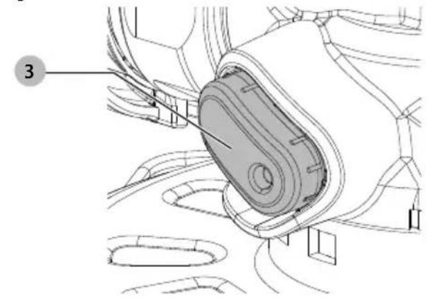
3 Spindle lock button
4 Spindle
5 Side handle
6 Backing flange
7 Locking flange
8 Guard
9 Clip-on guard
10 Guard release lever
11 Battery pack
12 Battery release button
13 Hex wrench
Intended Use
Your cordless angle grinder has been designed for professional cutting, grinding, sanding and wire brush applications.
Do not use under wet conditions or in the presence of flammable liquids or gases.
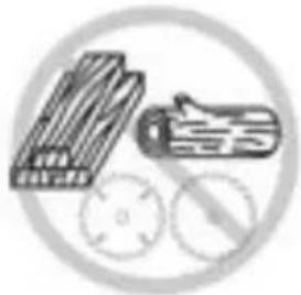
▲ANGER: Do not use for wood cutting or woodcarving. Do not use toothed blades of any kind. Serious injury can result. Your cordless angle grinder is a professional power tool.
Do not let children come into contact with the tool. Supervision is required when inexperienced operators use this tool.
- Young children and the infirm. This appliance is not intended for use by young children or infirm persons without supervision.
- This product is not intended for use by persons (including children) suffering from diminished physical, sensory or mental abilities; lack of experience, knowledge or skills unless they are supervised by a person responsible for their safety. Children should never be left alone with this product.
Features
Electronic Clutch
The electronic torque limiting clutch reduces the maximum torque reaction transmitted to the operator in case of jamming of a disc. This feature also prevents the gearing and electric motor from stalling. The torque limiting clutch has been factory-set and cannot be adjusted.
Power-OFF™ Overload Protection
The power supply to the motor will be reduced in case of motor overload. With continued motor overload, the tool will shut off. The switch will need to be released then depressed to restart tool. The tool will power off each time the current load reaches the overload current value (motor burn-up point). If continued overload shutdowns occur, apply less force/weight on the tool until the tool will function without the overload engaging.
Soft Start Feature
The soft start feature allows a slow speed build-up to avoid an initial jerk when starting. This feature is particularly useful when working in confined spaces.
No-Volt
The No-volt function stops the grinder restarting without the switch being cycled if there is a break in the power supply.
ASSEMBLY AND ADJUSTMENTS
WARNING: To reduce the risk of serious personal injury, turn tool off and disconnect battery pack before making any adjustments or removing/installing attachments or accessories. An accidental start-up can cause injury.
WARNING: Use only DEWALT batteries and chargers.
Inserting and Removing the Battery Pack from the Tool (Fig. H)
nOTE: Make sure your battery pack 11 is fully charged.
To Install the Battery Pack into the Tool Handle
- Align the battery pack with the rails inside the tool's handle (Fig. H).
- Slide it into the handle until the battery pack is firmly seated in the tool and ensure that you hear the lock snap into place.
To Remove the Battery Pack from the Tool
- Press the battery release button 12 and firmly pull the battery pack out of the tool handle.
- Insert battery pack into the charger.
Fuel Gauge Battery Packs (Fig. H)
Some DEWALT battery packs include a fuel gauge which consists of three green LED lights that indicate the level of charge remaining in the battery pack.
To actuate the fuel gauge, press and hold the fuel gauge button 28. A combination of the three green LED lights will illuminate, designating the level of charge left. When the level of charge in the battery is below the usable limit, the fuel gauge will not illuminate and the battery will need to be recharged.
NOTE: The fuel gauge is only an indication of the charge left on the battery pack. It does not indicate tool functionality and is subject to variation based on product components, temperature and end-user application.
Attaching Side Handle (Fig. B)
WARNING: Before using the tool, check that the handle is tightened securely. Screw the side handle extension piece 27 tightly into one of the holes on either side of the gear case. The side handle 5 should always be used to maintain control of the tool at all times.
Mounting the Clip-on Guard (Fig. A, C, D)
The clip-on guard converts a Type B guard into a Type A guard.
- Place the clip-on guard 9 onto the Type B guard so the hook 14 on the end of the clip-on guard aligns with the edge 15 of the Type B guard.
- Press down on the clip-on guard lever 16 until the lock button 17 engages with the locking hook 18. The clip-on guard is now locked in place.
- To remove the clip-on guard, press the lock button toward the clip-on guard lever and the clip-on lever will release. The clip-on lever can now be lifted, and the clip-on guard can be removed from the Type B guard.
Guards
AUTION: Guards must be used with all grinding wheels, cutting wheels, sanding flap discs, wire brushes, and wire wheels. The tool may be used without a guard only when sanding with conventional sanding discs. Refer to Figure A to see guards provided with the unit. Some applications may require purchasing the correct guard from your local dealer or authorised service centre.
AUTION: When using a Type 1/41/Type A (cut-off)/Type B with Clip-on wheel guard for facial grinding, the wheel guard may interfere with the workpiece causing poor control.
AUTION: When using a Type 27/Type B (grinding)/Type B with Clip-on wheel guard for cutting-off operations with bonded abrasive wheels, there is an increased risk of exposure to emitted sparks and particles, as well as exposure to wheel fragments in the event of wheel burst.
AUTION: When using a Type 1/41/Type A (cut-off), Type 27/Type B (grinding) wheel guard for cutting-off and facial operations in concrete or masonry, there is an increased risk of exposure to dust and loss of control resulting in kickback.
AUTION: When using a Type A (cut-off), Type B (grinding) wheel guard with a wheel-type wire brush with a thickness greater than the maximum thickness as specified in Technical Data, the wires may catch on the guard leading to breaking of wires.
NOTE: Edge grinding and cutting can be performed with Type 27 wheels designed and specified for this purpose; 6.3 mm thick wheels are designed for surface grinding while thinner Type 27 wheels need to be examined for the manufacturer's label to see if they can be used for surface grinding or only edge grinding/cutting. A Type 1/41/Type A/Type B with Clip-on (cut-off) wheel guard must be used for any wheel where surface grinding is forbidden. A Type 1/41/Type A/Type B with Clip-on (cut-off) (previously called Type 1/41) wheel guard must be used for any dual purpose (combined grinding and cutting-off abrasive) wheels. Cutting can also be performed by using a
Type 1/41 wheel and a Type 1/41/Type A/Type B with Clip-on cut-off wheel guard previously called Type 1/41 guard.
NOTE: Refer to the Accessory and Guard Applications Chart to select the proper guard/accessory combination.
Mounting and Adjusting the Guard (Fig. E)
WARNING: To reduce the risk of serious personal injury, turn tool off and disconnect battery pack before making any adjustments or removing/installing attachments or accessories. An accidental start-up can cause injury.
Adjusting the Guard
For guard adjustment, the guard release lever 10 engages one of the alignment holes 19 on the guard collar.
Mounting the Guard (Fig. E)
- Press the guard release lever 10.
- While holding the guard release lever open, align the lugs 20 on the guard with the slots 21 on the gear case.
- Keeping the guard release lever open, push the guard down until the guard lugs engage and rotate them in the groove on the gear case hub. Release the guard release lever.
- With the spindle facing the operator, rotate the guard clockwise into the desired working position. Press and hold the guard release lever 10 to rotate the guard in the anti-clockwise direction.
NOTE: The guard body should be positioned between the spindle and the operator to provide maximum operator protection.
The guard release lever should snap into one of the alignment holes 19 on the guard collar. This ensures that the guard is secure.
- To remove the guard, follow steps 1–3 of these instructions in reverse.
Flanges and Wheels
Mounting Non-Hubbed Wheels (Fig. F)
WARNING: Failure to properly seat the flange/clamp nut/wheel could result in serious injury (or damage to the tool or wheel).
CAUTION: Included flanges must be used with depressed centre Type 27 and Type 42 grinding wheels and Type 41 cutting wheels. Refer to the Accessory and Guard Applications for more information.
WARNING: A closed, two-sided cutting wheel guard is required when using abrasive cutting wheels or diamond-coated cutting wheels.
WARNING: To prevent wheel from coming off, always fully tighten the locking flange with provided wrench.
WARNING: Use of a damaged flange or guard or fail ure to use proper flange and guard can re sult in injury due to wheel breakage and wheel contact. Refer to the Accessory and Guard Applications for more information.
-
Place the tool on a table, guard up.
-
Install the backing flange 6 on spindle 4 with the raised centre (pilot) facing the wheel. Press the backing flange into place.
-
Place wheel 22 against the backing flange, centring the wheel on the raised centre (pilot) of the backing flange.
-
While depressing the spindle lock button and with the hex depressions facing away from the wheel, thread the locking
flange 7 on spindle so that the lugs engage the two slots in the spindle.
- While depressing the spindle lock button, tighten the locking flange 7 using the supplied wrench. (Only use a locking flange if it is in perfect condition.) Refer to the Accessory and Guard Applications to see flange details.
- To remove the wheel, reverse the above procedure.
Mounting Sanding Backing Pads (Fig. A, G)
NOTE: Use of a guard with sanding discs that use backing pads, often called fibre resin discs, is not required. Since a guard is not required for these accessories, the guard may or may not fit correctly if used.
WARNING: Failure to properly seat the flange/clamp nut/wheel could result in serious injury (or damage to the tool or wheel).
WARNING: Proper guard must be reinstalled for grinding wheel, cutting wheel, sanding flap disc, wire brush or wire wheel applications after sanding applications are complete.
- Place the tool on a table, spindle up.
- Install the backing flange 6 on spindle 4 with the raised centre (pilot) facing the wheel. Press the backing flange into place.
- Place or appropriately thread backing pad 23 on the spindle.
- Place the sanding disc 24 on the backing pad.
- While depressing spindle lock 3, thread clamp nut 25 on spindle, piloting the raised hub on the clamp nut into the centre of san ding disc and backing pad.
- Tighten the clamp nut by hand. Then depress the spindle lock button while turning the sanding disc until the sanding disc and clamp nut are snug.
- To remove the wheel, grasp and turn the backing pad and sanding pad while depressing the spindle lock button.
Mounting and Removing Hubbed Wheels (Fig. A)
Hubbed wheels install directly on the threaded spindle. Thread of accessory must match thread of spindle.
- If it is not needed, remove the backing flange by pulling it away from tool.
IMPORTANT: Removing the backing flange should only be done if the hubbed accessory has recessed portion of the threads that clear the unthreaded portion of the spindle.
Non-recessed threads
Use with backing flange
Recessed threads
Remove backing flange
- Thread the wheel on the spindle 4 by hand.
- Depress the spindle lock button ③ and use a wrench to tighten the hub of the wheel.
- Reverse the above procedure to remove the wheel.
NOTICE: Failure to properly seat the wheel before turning the tool on may result in damage to the tool or the wheel.
Mounting Wire Cup Brushes and Wire Wheels (Fig. A)
WARNING: Failure to properly seat the flange/clamp nut/wheel could result in serious injury (or damage to the tool or wheel).
AUTION: To reduce the risk of personal injury, wear work gloves when handling wire brushes and wheels. They can become sharp.
AUTION: To reduce the risk of damage to the tool, wheel or brush must not touch guard when mounted or while in use. Undetectable damage could occur to the accessory, causing wires to fragment from accessory wheel or cup. Wire cup brushes or wire wheels install directly on the threaded spindle. Use only wire brushes or wheels provided with a threaded hub. These accessories are available at extra cost from your local dealer or authorised service centre.
-
Place the tool on a table, guard up.
-
If it is not needed, remove the backing flange by pulling it away from tool (Refer to the illustration in Mounting and Removing Hubbed Wheels to determine if the backing flange is needed).
- Thread the wheel on the spindle by hand.
- Depress spindle lock button 3 and use a wrench on the hub of the wire wheel or brush to tighten the wheel.
- To remove the wheel, reverse the above procedure.
NOTICE: To reduce the risk of damage to the tool, properly seat the wheel hub before turning the tool on.
Prior to Operation
• Install the guard and appropriate disc or wheel. Do not use excessively worn discs or wheels.
- Be sure the threaded locking flange is mounted correctly. Follow the instructions given in the Accessory and Guard Applications Chart.
- Make sure the disc or wheel rotates in the direction of the arrows on the accessory and the tool.
- Do not use a damaged accessory. Before each use, inspect the accessory such as abrasive wheels for chips and cracks, backing pad for cracks, tear or excess wear, wire brush for loose or cracked wires. If power tool or accessory is dropped, inspect for damage or install an undamaged accessory. After inspecting and installing an accessory, position yourself and bystanders away from the plane of the rotating accessory and run the power tool at maximum no-load speed for one minute. Damaged accessories will normally break apart during this test time.
OPERATION
Instructions for Use
WARNING: Always observe the safety instructions and applicable regulations.
WARNING: To reduce the risk of serious personal injury, turn tool off and disconnect battery pack before making any adjustments or removing/installing attachments or accessories.
An accidental start-up can cause injury.
WARNING:
- Ensure all materials to be ground or cut are secured in place.
- Secure and support the workpiece. Use clamps or a vise to hold and support the workpiece to a stable platform. It is important to
clamp and support the workpiece securely to prevent movement of the workpiece and loss of control. Movement of the workpiece or loss of control may create a hazard and cause personal injury.
• Always wear regular working gloves while operating this tool.
• The gear becomes very hot during use.
- Apply only a gentle pressure to the tool. Do not exert side pressure on the disc.
- Always install the guard and appropriate disc or wheel. Do not use excessively worn disc or wheel.
- Avoid overloading. Should the tool become hot, let it run a few minutes under no load condition to cool the accessory. Do not touch accessories before they have cooled. The discs become very hot during use.
- Never work with the grinding cup without a suitable protection guard in place.
- Do not use the power tool with a cut-off stand.
- Never use blotters together with bonded abrasive products.
- Be aware, the wheel continues to rotate after the tools is switched off.
Proper Hand Position (Fig. I)
WARNING: To reduce the risk of serious personal injury,
ALWAYS use proper hand position as shown.
WARNING: To reduce the risk of serious personal injury,
ALWAYS hold securely in anticipation of a sudden reaction.
Proper hand position requires one hand on the main handle 26 and the other hand on the auxiliary handle 5, as shown in Fig. I.
Paddle Switch (Fig. A)
AUTION: Hold the side handle and body of the tool firmly to maintain control of the tool at start up and during use and until the wheel or accessory stops rotating. Make sure the wheel has come to a complete stop be fore laying the tool down.
NOTE: To reduce unexpected tool movement, do not switch the tool on or off while under load conditions. Allow the grinder to run up to full speed before touching the work surface. Lift the tool from the surface before turning the tool off. Allow the tool to stop rotating before putting it down.
- To turn the tool on, push the lock-off lever 2 toward the front (gear case) of the tool, then depress the paddle switch 1. The tool will run while the switch is depressed.
- Turn the tool off by releasing the paddle switch.
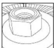
Spindle Lock (Fig. J)
The spindle lock 3 is provided to prevent the spindle from rotating when installing or removing wheels. Operate the spindle lock only when the tool is turned off, when the battery has been removed, and has come to a complete stop.
NOTICE: To reduce the risk of damage to the tool, do not engage the spindle lock while the tool is operating. Damage to the tool will result and attached accessory may spin off possibly resulting in injury.
To engage the lock, depress the spindle lock button and rotate the spindle until you are unable to rotate the spindle further.
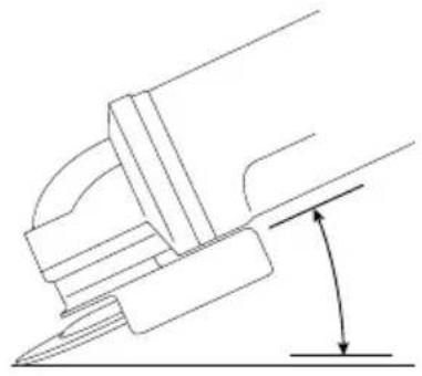
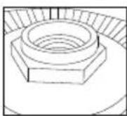
Surface Grinding, Sanding and Wire Brushing (Fig. K)
AUTION: Always use the correct guard per the instructions in this manual.
To perform work on the surface of a workpiece:
- Allow the tool to reach full speed before touching the tool to the work surface.
- Apply minimum pressure to the work surface, allowing the tool to operate at high speed. Material removal rate is greatest when the tool operates at high speed.
- Maintain an appropriate angle between the tool and work surface. Refer to the chart according to particular function.
| Function Angle | |
| Grinding | 20°-30° |
| Sanding with Flap Disc 5°-10° | |
| Sanding with Backing Pad 5°-15° | |
| Wire Brushing 5°-10° | |
-
Maintain contact between the edge of the wheel and the work surface.
-
If grinding, sanding with flap discs or wire brushing move the tool continuously in a forward and back motion to avoid creating gouges in the work surface.
- If sanding with a backing pad, move the tool constantly in a straight line to prevent burning and swirling of work surface.
NOTE: Allowing the tool to rest on the work surface without moving will damage the workpiece.
- Remove the tool from work surface before turning tool off. Allow the tool to stop rotating before laying it down.
AUTION: Use extra care when working over an edge, as a sudden sharp movement of grinder may be experienced.
Precautions To Take When Working on a Painted Workpiece
- Sanding or wire brushing of lead-based paint is NOT RECOMMENDED due to the difficulty of controlling the contaminated dust. The greatest danger of lead poisoning is to children and pregnant women.
- Since it is difficult to identify whether or not a paint contains lead without a chemical analysis, we recommend the following precautions when sanding any paint:
Personal Safety
- No children or pregnant women should enter the work area where the paint sanding or wire brushing is being done until all clean up is completed.
- A dust mask or respirator should be worn by all persons entering the work area. The filter should be replaced daily or whenever the wearer has difficulty breathing.
NOTE: Only those dust masks suitable for working with lead paint dust and fumes should be used. Ordinary painting masks do not offer this protection. Consult your local hardware dealer for the proper approved mask.
- NO EATING, DRINKING or SMOKING should be done in the work area to prevent ingesting contaminated paint particles. Workers should wash and clean up BEFORE eating, drinking or smoking. Articles of food, drink, or smoking should not be left in the work area where dust would settle on them.
Environmental Safety
- Paint should be removed in such a manner as to minimise the amount of dust generated.
- Areas where paint removal is occurring should be sealed with plastic sheeting of 4 mils thickness.
- Sanding should be done in a manner to reduce tracking of paint dust outside the work area.
Cleaning and Disposal
- All surfaces in the work area should be vacuumed and thoroughly cleaned daily for the duration of the sanding project. Vacuum filter bags should be changed frequently.
- Plastic drop cloths should be gathered up and disposed of along with any dust chips or other removal debris. They should be placed in sealed refuse receptacles and disposed of through regular trash pick-up procedures.
During clean up, children and pregnant women should be kept away from the immediate work area. - All toys, washable furniture and utensils used by children should be washed thoroughly before being used again.
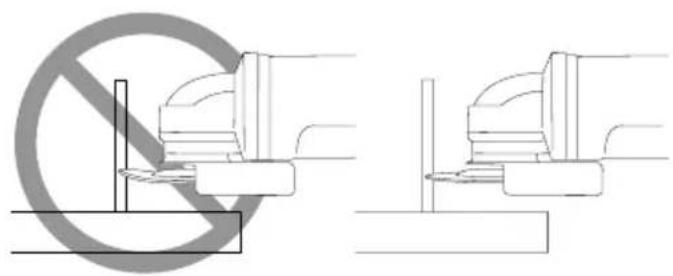
Edge Grinding and Cutting (Fig. L)
WARNING: Do not use edge grinding/cutting wheels for surface grinding applications because these wheels are not designed for side pressures encountered with surface grinding. Wheel breakage and injury may result.
AUTION: Wheels used for edge grinding and cutting may break or kick back if they bend or twist while the tool is being used. In all edge grinding/cutting operations, the open side of the guard must be positioned away from the operator.
NOTICE: Edge grinding/cutting with a Type 27 wheel must be limited to shallow cutting and notching—less than 13 mm in depth when the wheel is new. Reduce the depth of cutting/notching equal to the reduction of the wheel radius as it wears down. Refer to the Accessory and Guard Applications for more information. Edge grinding/cutting with a Type 41 wheel requires usage of a Type A guard.
- Allow the tool to reach full speed before touching the tool to the work surface.
- Apply minimum pressure to the work surface, allowing the tool to operate at high speed. Grinding/cutting rate is greatest when the tool operates at high speed.
- Position yourself so that the open-underside of the wheel is facing away from you.
- Once a cut is begun and a notch is established in the workpiece, do not change the angle of the cut. Changing the angle will cause the wheel to bend and may cause wheel breakage. Edge grinding wheels are not designed to withstand side pressures caused by bending.
- Remove the tool from the work surface before turning the tool off. Allow the tool to stop rotating before laying it down.
Cutting Metal
For cutting with bonded abrasives, always use the Type A/Type B with Clip-on guard.
When cutting, work with moderate feed, adapted to the material being cut. Do not exert pressure onto the cutting disc, tilt or oscillate the machine.
Do not reduce the speed of running down cutting discs by applying sideward pressure.
The machine must always work in an upgrinding motion. Otherwise, the danger exists of it being pushed uncontrolled out of the cut.
When cutting profiles and square bar, it is best to start at the smallest cross section.
Rough Grinding
Never use a cutting disc for roughing. Always use the guard Type B.
The best roughing results are achieved when setting the machine at an angle of 30^ to 40^ . Move the machine back and forth with moderate pressure. In this manner, the workpiece will not become too hot, does not discolour and no grooves are formed.
Working Advice
Exercise caution when cutting slots in structural walls.
Slots in structural walls are subject to the country-specific regulations. These regulations are to be observed under all circumstances. Before beginning work, consult the responsible structural engineer, architect or the construction supervisor.
MAINTENANCE
Your power tool has been designed to operate over a long period of time with a minimum of maintenance. Continuous satisfactory operation depends upon proper tool care and regular cleaning.
WARNING: To reduce the risk of serious personal injury, turn tool off and disconnect battery pack before making any adjustments or removing/installing attachments or accessories. An accidental start-up can cause injury.
The charger and battery pack are not serviceable.
Please refer to the back page of this manual for service centre contact information, or visit www.2helpU.com.
Lubrication
Your power tool requires no additional lubrication.
Cleaning
WARNING: Electrical shock and mechanical hazard. Disconnect the plug from the power source and/or remove the battery pack, if detachable, from the product before cleaning.
WARNING: To ensure safe and efficient operation, always keep the product and the ventilation slots (if applicable) clean. Ventilation slots can be cleaned using a dry, soft non-metallic brush and/or a suitable vacuum cleaner. Do not use water or any cleaning solutions.
WARNING: Blow dirt and dust out of the main housing with dry air as often as dirt is seen collecting in and around the ventilation slots. Wear approved eye protection and approved dust mask when performing this procedure.
WARNING: Never use solvents or other harsh chemicals for cleaning the non-metallic parts of the product. These chemicals may weaken the materials used in these parts. Use a cloth dampened only with water and mild soap. Never let any liquid get inside the product. Never immerse any part of the product into a liquid.
Optional Accessories
WARNING: Since accessories, other than those offered by DEWALT, have not been tested with this product, use of such accessories with this tool could be hazardous. To reduce the risk of injury, only DEWALT recommended accessories should be used with this product.
WARNING: Do not use a bonded abrasive wheel that is past its expiration (EXP) date as marked near center of wheel (if provided). Expired wheels are more likely to burst and cause serious injury. Store bonded abrasive wheels in dry location
without temperature or humidity extremes. Destroy expired or damaged wheels so they cannot be used.
Consult your dealer for further information on the appropriate accessories.
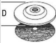
| Max. [mm] | [mm] | Min. Rotation [min.-1] | Peripheral speed [m/s] | Threaded hole length [mm] | ||
| D b d | ||||||
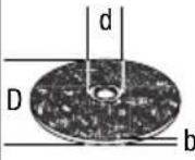 | 115 6 | 22,23 | 11,500 80 – | |||
| 125 6 | 22,23 | 11,500 80 – | ||||
 | 115 – - 1 | 1500 80 – | ||||
| 125 – - 1 | 1500 80 – | |||||
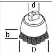 | 75 30 M14 | 11500 45 20.0 | ||||
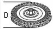 | 115 11 M14 | 11500 80 17*/11** | ||||
| 125 11 M14 | 11500 80 17*/11** | |||||
* Threaded hole height for recessed thread type where backing flange is removed.
** Threaded hole height for non-recessed thread type where backing flange is used.
Protecting the Environment


Products/batteries are recyclable, but if marked with the crossed-out bin, they must not be disposed of with normal household waste.
Run the batteries down completely and separate them, and separate any light sources from the product if possible. It is the user's responsibility to delete personal data from the product. Then take the waste to an official waste collection centre or a participating retailer who will often accept it free of charge. Packaging should be discarded based on the marked material code. Operating and safety instructions should only be discarded once the applicable product is no longer in use. Please check with your local community/municipality for waste management guidance. For further information, visit www.2helpU.com and scan the above QR code.
Additional Information for Guards and Accessories
| When using segmented diamond wheels, use only diamond wheels with a peripheral gap not greater than 10 mm and negative rake angle. | 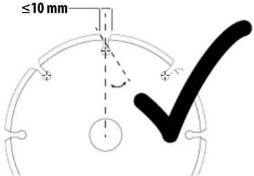 |
| DO NOT USEsegmented diamond wheels with a peripheral gap greater than 10 mm and/or a positive rake angle. | 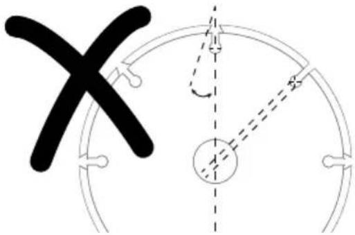 |
| For all grinding, sanding, and wheel type wire brushing accessories, the lowest portion of the accessory must be contained within the guard enclosure with 2 mm or greater clearance to the bottom lip of guard. |  |
Accessory and Guard Applications
| Accessory Type | Accessory | Guard | Assembly for Reference | ||
| Surface Grinding | Wheel Type 27 | 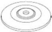 | 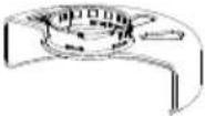 | 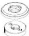 Type B (Grinding) Type B (Grinding) | 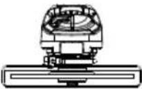 |
| Cutting Off | Wheel Type 41 (1A)(metal) | 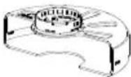 | 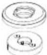 Type A (Closed cut off) Type A (Closed cut off)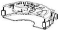 | 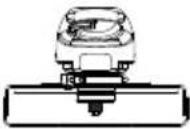 Type B guard with Clip-on guard Type B guard with Clip-on guard | |
| Wheel Type 42 (27A)(metal) | 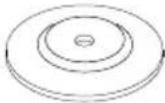 | 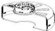 | 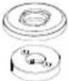 Type A (Closed cut off) Type A (Closed cut off) | 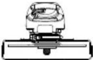 Type B guard with Clip-on guard Type B guard with Clip-on guard | |
| Abrasive Wheels For MaterialsOther Than Metal | 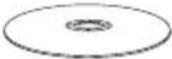 | 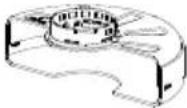 | 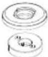 Type A (Closed cut off) Type A (Closed cut off)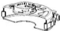 | 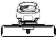 Type B guard with Clip-on guard Type B guard with Clip-on guard | |
| Dual Purpose(combined cut-off and grinding) | Dual Purpose Abrasive Wheel |  |  | 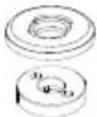 Type A (Closed cut off) Type A (Closed cut off)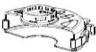 | 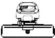 Type B guard with Clip-on guard Type B guard with Clip-on guard |
| Wire Brushing | Wheel-Type Wire Brush |  | 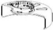 Type B (Grinding) Type B (Grinding) | 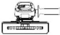 | |
| Accessory Type | Accessory | Guard | Assembly for Reference | ||
| Sanding | Flap Disc (Type 27 / Type 29) | 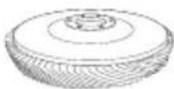 | 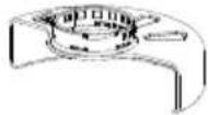  Type B (Grinding) Type B (Grinding) | 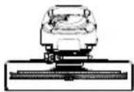 | |
| Flexible Abrasive(e.g., sandpaper)(supported by a flexiblebacking pad) | 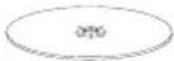 | 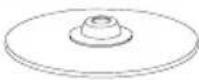  Guard not required Guard not required |  | ||
| ^6 Rubber backing pad and sanding clamp nut (included with rubber backing pad) available at additional cost from yourlocal D-EWALT dealer or authorised D-EWALT service centre. | |||||
| Guidelines for Guards and Accessories | ||
| Non-approved Wheels | Type 11 / T11 |  |
| Type 6 / T6 |  | |
| Hubbed Wheel Wrench | Hubbed wheel wrench available at additional cost from your local DEWALT dealer or authorised DEWALT service centre. |  |
RANGER: Do not use for wood cutting or woodcarving. Do not use toothed blades of any kind. Serious injury can result.
natural_image
Simple line drawing of stacked books and a pencil inside a circle with no text or symbolsnatural_image
Line drawing of a hexagonal nut on a circular base, with no text or symbols present.natural_image
Simple line drawing of stacked books and a pencil inside a circle with no text or symbolsPETITE MEULEUSE D'ANGLE
DCG404
Retirez la bride-support
natural_image
Simple line drawing of stacked books and a shoe with circular background elements (no text or symbols)SMERIGLIATRICE ANGOLARE PICCOLA
DCG404
natural_image
Illustration of stacked books and a gear with circular components (no text or symbols)KLEINE HAAKSE SLIJPMACHINE
DCG404
www.2helpU.com/DoC/ of www.2helpU.com/DoC/index/xxx*
WAARSCHUWING: Lees alle
BEWAAR ALLE WAARSCHUWINGEN EN INSTRUCTIES ALS TOEKOMSTIG REFERENTIEMATERIAAL
natural_image
Illustration of a notebook and a pencil with circular background symbols (no text or labels)TRÅDL∅S VINKELSLIPER
DCG404
natural_image
Illustration of a notebook and a pair of scissors with circular background symbols (no text or labels)REBARBADORA ANGULAR PEQUENA
DCG404
Documentos disponíveis online www.2helpU.com/DoC/ou www.2helpU.com/DoC/index/xxx ^3
natural_image
Illustration of stacked books and a pencil inside a circular frame with two circular holes (no text or symbols)PIENI KULMAHIOMAKONE
DCG404
natural_image
Simple line drawing of stacked books and a shoe with circular background elements (no text or symbols)LITEN VINKELSLIP
DCG404
DCB113, DCB115, DCB116, DCB117, DCB118, DCB132, DCB1102, DCB1104.
natural_image
Simple line drawing of stacked books and a pencil inside a circle with crossed-out tools (no text or symbols)KÜÇÜK AVUÇ TAŞLAMA MAKINESI DCG404
DCB113, DCB115, DCB116, DCB117, DCB118, DCB132, DCB1102, DCB1104.
Paket İçeriği
natural_image
Illustration of a notebook and a hand inside a circular frame with gear symbols (no text or labels)natural_image
Illustration of stacked books and a shoe with circular patterns (no text or symbols)| Australia / New Zealand Tel: Aust 1800 338 002Tel: NZ 0800 339 258 | www.dewalt.com.auwww.dewalt.co.nzsupport@dewalt.ausupport@dewalt.co.nz | |||
| Belgique et LuxembourgBelgië en Luxemburg | Tel: NL 32 15 47 37 63Tel: FR 32 15 47 37 64 | www.dewalt.besupport@dewalt.besupport@dewalt.be.fr | ||
| Danmark | Tel: | 70 20 15 10 | www.dewalt.dk | support@dewalt.dk |
| Deutschland | Tel: | 06126-21-0 | www.dewalt.desupport@dewalt.de | |
| Ελλάς | Tηλ: | 00302108981616 | www.dewalt.grsupport@dewalt.gr | |
| España | Tel: | 934 797 400 | www.dewalt.essupport@dewalt.es | |
| France | Tel: | 04 72 20 39 20 | www.dewalt.frsupport@dewalt.fr | |
| Schweiz, Suisse, Svizzera | Tel: 044 - 755 60 70 www.dewalt.ch | support@dewalt.ch.desupport@dewalt.ch.frsupport@dewalt.ch.it | ||
| Ireland | Tel: | 00353-2781800 | www.dewalt.iesupport@dewalt.ie | |
| Italia | Tel: 800-01435339 039-9590200 | www.dewalt.itsupport@dewalt.it | ||
| Nederlands | Tel: | 31 164 283 063 | www.dewalt.nlsupport@dewalt.nl | |
| Norge | Tel: 45 25 13 00 www.dewalt.no | support@dewalt.no | ||
| Österreich | Tel: 01 - 66116 - 0 www.dewalt.at | support@dewalt.at | ||
| Portugal | Tel: +351 214667500 www.dewalt.pt | support@dewalt.pt | ||
| Suomi | Puh: 010 400 4333 www.dewalt.fi | support@dewalt.fi | ||
| Sverige | Tel: | 031 68 61 60 | www.dewalt.sesupport@dewalt.se | |
| Türkiye | Tel: +90 216 665 2900 | tr.dewalt.globalsupport@dewalt.com.tr | ||
| United Kingdom | Tel: (+44) (0)1753 260094 | www.dewalt.co.uksupport@dewalt.co.uk | ||
| Middle East Africa | Tel: 971 4 812 7400 www.dewalt.aesupport@dewalt.ae | |||