FM4BM30FBI - Fridge Fulgor Milano - Free user manual and instructions
Find the device manual for free FM4BM30FBI Fulgor Milano in PDF.

User questions about FM4BM30FBI Fulgor Milano
0 question about this device. Answer the ones you know or ask your own.
Ask a new question about this device
Download the instructions for your Fridge in PDF format for free! Find your manual FM4BM30FBI - Fulgor Milano and take your electronic device back in hand. On this page are published all the documents necessary for the use of your device. FM4BM30FBI by Fulgor Milano.
USER MANUAL FM4BM30FBI Fulgor Milano
| FULGOR MILANO | |
| FM4BM30(I)FBI FM4BM36(I)FBI FM4FBM36(I)FBI | |
| REFRIGERATOR RéFRIGÉRATEUR | EN INSTALLATION MANUAL FR MANUEL D'INSTALLATION |
TABLE OF CONTENTS PAGE
1 - Symbols and Their Meanings 2
Disposing the packaging materials 2
Product weight 3
Load bearing capacity of the doors 3
2 - Installation Place 4
Furniture 4
Ventilation 5
Electrical Connection 5
Water Connection 5
3-Tool list 6
4 - Alternatives for installation 7
5 - Preparation for installation 8
Cabinet Dimensions 8
Location of the Electrical Wiring 9
Location of the Water System 9
Product Dimensions 10
Unpacking 17
Removing Accessories from the Back 18
Removing Mounting Parts in the Freezer 19
Compartment 1
Removing the Freezer Drawer Bin 20
Removing the Freezing Printer 20
Removing the Lower Ventilation Assembly 21
Removing the Upper Ventilation Part 21
6 - Preparing for installation 22
Mounting the Anti-Tip Brackets 22
Alternative Anti-Tip Method 23
Preparing the Water Hose and the Power Plug 23
7-Installation into the cabinet 24
Taking the Appliance from the Wooden Pallet 24
Placing the Appliance into the Cabinet 24
Adjusting the Height of the Appliance in the 25
Cabinet 25
Adjusting the Appliance with Respect to the 26
Side Walls 26
Attaching the Cabinet Connection Brackets 26
8- Installing at the bottom 28
Water connection 28
Attaching the Upper Ventilation Part 28
Attaching the Lower Ventilation Assembly 29
Attaching the Decorative Trim Parts 29
Choosing the Door Thickness 29
TABLE OF CONTENTS PAGE
9 - Door overlay preparation 31
Removing the Mechanism Covers 31
Removing the Door Panel-Adjustment 31
Mechanisms on the Refrigerator 31
Preparing the Door Overlay Panels 31
Preparing the Fridge Door Overlay Panel 32
Preparing the Freezer Door Overlay Panel 33
Installing the Fridge Door Overlay Panel 34
How to align the fridge door with bolts 34
Installing the Freezer Door Overlay Panel 40
How to align the freezing door overlay panel 41
to the lower section 41
10-Hinge adjustment 45
Adjusting the Strength of the Hinges 45
11-Changing the swing of the door 46
Removing the Fridge Door 46
Removing and Preparing the Fridge Inner 18
Door 48
Replacing the Hinges 48
Installing the Fridge Door 49
12-Dual installation 50
Cabinet Dimensions 50
Location of the Electrical Wiring 50
Location of the water system 51
Mounting Part Lists 52
Attaching the fasteners and connecting 54
bracket 54
Adjusting the height of the refrigerator in the 56
cabinet 36
Screwing the bracket furniture on the cabinet 56
side walls 86
Screwing the bracket furniture on the cabinet 56
top wall 88
Attaching the decorative trim parts 56
Completion installation 57
Symbols used in the installation manual are as follows.
| Icon Mode Description |
| i Important information or useful usage tips. |
| WARNING: Conditions that may damage the product or its operating functions. |
| ATTENTION: Conditions containing serious injury risk. |
| Conditions containing electric shock risk. |
| Packaging materials of the product have been manufactured from recyclable materials. |
Disposing the packaging materials
The package has been designed to protect the product during transport.
The packaging materials used for the product do not harm the nature during disposal and they need to be recycled.
All plastic packaging materials, bags etc. must be disposed safely and kept out of the reach of children.
Please return the packaging to your dealer.

WARNING
This installation manual has been prepared to help installation teams. The User Manual provided with the product must also be taken into consideration.
You may get seriously injured and your product may get damaged if you ignore the warnings given in this or other manuals. Please read the following carefully.
R600a Refrigerant

WARNING
This product contains R600a isobutane refrigerant, which is a very eco-friendly natural gas. However, it is also flammable. Please follow the warnings given below:
If the product has been transported horizontally, you must wait for 4 hours minimum before plugging it in.
The following instructions must be followed during installation:
- Dimensions of the installation area must be suitable.
- Dimensions, features and position of the object used to support and fix the product to this area must be suitable.
Minimum clearances between product parts and surrounding structures must be suitable.
- Minimum dimensions and proper organization of ventilation holes must be observed.
The product must be connected to the mains power,
and corresponding connections of other components must be suitable.
- The product must be disconnectable from the power supply after installation.
- The socket or fuse must be accessible to de-energize the product.
- Extension cables or ungrounded (two-terminal) adapters must not be used.

ATTENTION
You must wear gloves and eye protectors when installing the product.
You must also take measures against high noise levels when using power tools.

ATTENTION
Make sure that your product is suitable for your local mains.

ATTENTION
The product must be installed by a qualified technician according to the installation instructions.

WARNING
The product may tip over since it is quite heavy. For this reason, precautions must be taken against tipping over.
The doors of the product must be kept closed until it reaches the destination, and it must be transported in accordance with the installation instructions.
| Climate range Ambient temperature of the room For Best results | ||
| SN | Between +50°F (10oC) and +90°F (32°C) | This appliance has been designed to be used in certain climate ranges (ambient temperatures). It must not be used out of this range. |
| N | Between +60°F (16°C) and +90°F (32°C) | |
| ST | Between +60°F (16°C) and +110°F (38°C) | |
| T | Between +60°F (16°C) and +120°F (43°C) | |
Product weight
| Category FM4BM30(I)FBI FM4BM36(I)FBI FM4FBM36(I)FBI | |
| Product weight 361lbs (164kg) 373lbs (169kg) 355lbs (161kg) |
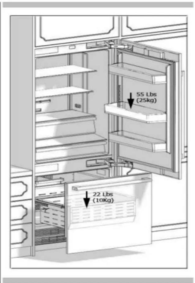
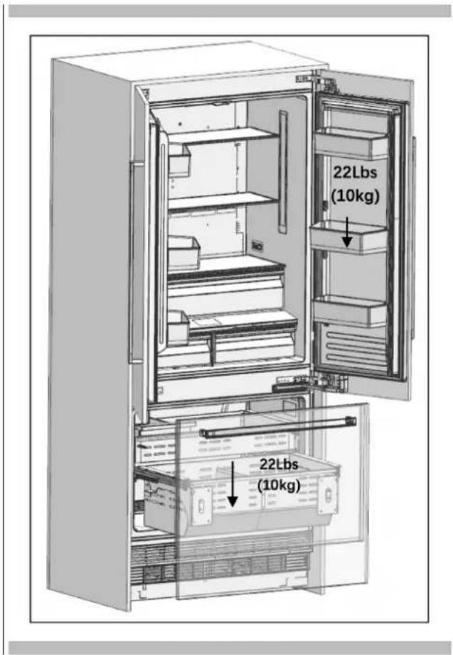
Load bearing capacity of the doors (does not include overlay panel weight)
| Max load FM4BM30(I)FBI FM4BM36(I)FBI FM4FBM36(I)FBI | ||
| Fridge door(s) | 55lbs (25kg) | 55lbs (25kg) 22lbs (10kg) ea. |
| Freezer drawer | 22lbs (10kg) | 22lbs (10kg) 22lbs (10kg) |
FM4BM3O(II)FBI
FM4BM36(I)FBI
FM4FBM36(I)FBI
You must follow the instructions below:
- The floor on which the product will be installed must be capable of bearing 1,200 pounds (544 kg) minimum.
- Kitchen floor and the bottom of the product must be at the same level. Otherwise, problems may occur with the air circulation of the product.
- There must be no objects preventing the installation of the product at the back and on the side walls of the product's installation place.
The power socket must be in the correct place. - The dimensions of the furniture where the product will be installed must be in strict conformity with the dimensions given in the manual.
- Do not install the product with the fridge and the freezer directly next to each other without the use of the correct side by side joining kit. Otherwise, condensation and damage may occur in the product. (Please Cabin Installation" for detailed information)
- The flatness of the floor where the product will be installed must be checked with a Bubble Level Tool.
- The installation area must not be subjected to direct sunlight, and it must be away from heat sources, ovens, radiators etc.
The ambient temperature must be between 55 F (13 C) and 110 F (43 C). Otherwise, functional errors arise when the product is running.
If it is not possible to avoid installing the product near a heat source, the minimum clearances given below must be maintained between the product and the said source:
1 1 / 4'' (3 cm) from electric hobs or ovens
12" (30 cm) from gas or fuel operated hobs or ovens.
Please observe the following rules:
- The circuit breaker or fuse must be easily accessible in case of an emergency.
- Plug or cable must not touch the back surface of the product. Otherwise, it may get damaged due to the vibration of the product.
- Do not connect the plugs of other appliances behind this product.
- If the humidity or salinity level is high where the product is used, corrosion may be seen on the outer surface of the product.
- Keep the installation room dry and well-cleaned to avoid corrosion.
To avoid the risk of electric shock:
- Connect the plug to a grounded 3-pin socket.
- Do not remove the ground terminal of the plug.
- Do not use adapters.
- Do not use extension cables.

ATTENTION
Failure to follow these instructions may result in death, fire, or electric shock. Connecting the grounding conductor of the equipment to an improper place may lead to electric shock. Please have the grounding checked by a qualified electrician or service technician if you have any doubt about the proper grounding of the product.
Installation, repair, and other procedures performed by unqualified persons may cause danger. Before installing the appliance, make sure that the voltage, load, and circuit current parameters on the data plate are in compliance with the power mains in your house.
The appliance is provided with a NEMA 5-15 P plug and a 3-pin power cable which is in the UL list and ready to be connected to a 120V 60Hz power supply. Fuse is 15A . The appliance must be connected to a 3-pin socket. The receptacle must be installed only by a licensed electrician. If the electrical wiring or the electric power supply of the house needs alteration, the necessary procedures must be performed by a qualified electrician.

ATTENTION
Do not install your refrigerator:
In outdoor areas.
In environments where water is dripping.
In environments where temperature is lower than 55 F (13 C).
Furniture
Make sure that the furniture where you will install the appliance has been safely mounted in your kitchen. Your furniture must be connected to the floor and the wall properly and with suitable connections.
For the best installation, clearances between the furniture and the product must be in compliance with the values specified in the installation instructions.
Side walls must be free of clearances and their surfaces must be flat.
Minimum thickness of the side walls must be 5 / 8'' (16 mm).
Minimum thickness of the doors to be attached to the product must be " (19 mm)

ATTENTION
The stainless steel door option is also available
Ventilation
Vent holes where the air enters and exits the unit must not be blocked or obstructed. In addition, you must periodically clean the dust and dirt that accumulate on these holes over time.
Electrical Connection
- Never use an extension cable.
- The power socket absolutely must be grounded and checked by an authorized person.
- Location of the electrical wiring must comply with the dimensions specified in the manual.

ATTENTION
RISK OF ELECTRIC SHOCK
Electrical grounding is necessary. This appliance is equipped with a three-pin plug to protect you against possible electric shocks.
- Do not remove the round grounding terminal from the plug.
- Do not use two-pin grounding adapters.
- Do not use extension cables to energize the product.

ATTENTION
Do not connect the grounding cable to the gas pipe. Please have the grounding checked by a qualified electrician

WARNING
Please wait for 3-6 hours before energizing the product to protect it against possible damage. This way, the refrigerant and the lubricants in the system get balanced.
Water Connection
- Pressure of the mains water must be in compliance with the values specified in the manual.
- The location of the water system must comply with the dimensions specified in the manual.

IMPORTANT INFORMATION
Bypass is recommended for the water filtering system if a reverse osmosis system is used.
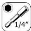
EN 3 - Tool list
Tools to be used when installing the product are as follows:
Icon Mode Description

Cordless Drill

Safety Goggles

12 Wrench

Hammer

Ladder

Ø2.4 Drill Bit

8.0 Drill Bit

Box Cutter

Safety Gloves

Tape Measure

Phillips Bt

Masking Tape

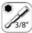
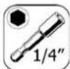
3/8" Socket

1/4" Socket

Appliance Cart

Standard bit screwd river

Bubble Level Tool

Torx 20 bit

Torx 25 bit

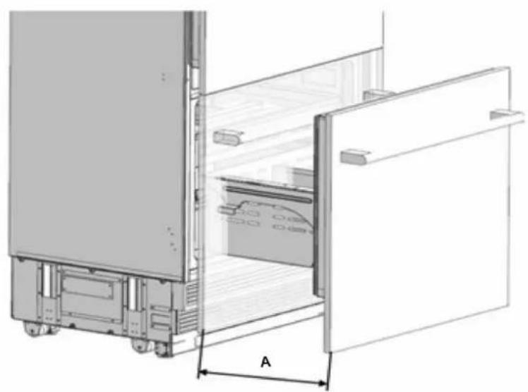
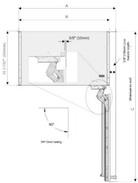
WARNING
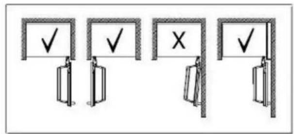
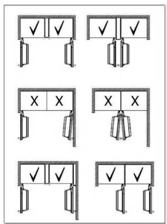
The product can be placed in various ways based on the kitchen design. It must be installed in a place where it is ensured that the door can be opened and closed properly. If the doors cannot be opened 90 degrees at least, you cannot completely open the drawers inside the product. See door swing dimensions on page 19 - 22.

WARNING
Door swing should be done before installing the door overlay panels - see pages 76-78 for instructions.
- Single cabin placement methods
Dual cabin placement methods
EN 5 - Preparation for installation
The instructions below have been prepared according to Built-in type.
Built-in: The Appliance and Panels fully seat into the opening, and dedicated cabinet is placed between the two kitchen cabinets or decorative columns.
This is the most common installation scenario.
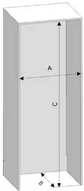
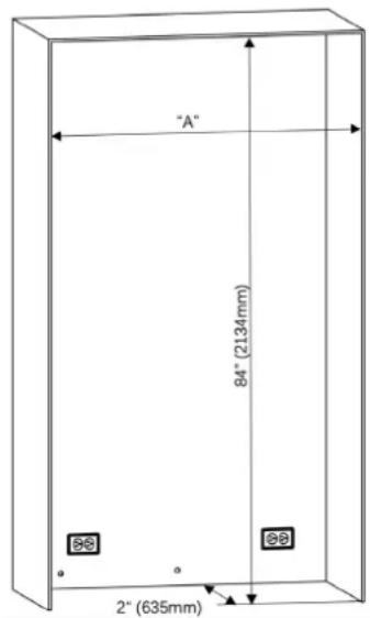
Cabin Dimensions
- Cabinet dimensions below must be checked before starting the installation.
| Category FM4BM30(I)FBI FM4BM36(I)FBI FM4FBM36(I)FBI | ||
| A width 30" (762mm) | 36" (914mm) | 36" (914mm) |
| B depth 25" (635mm) | 25" (635mm) | 25" (635mm) |
| C height 84" (2134mm) | 84" (2134mm) | 84" (2134mm) |
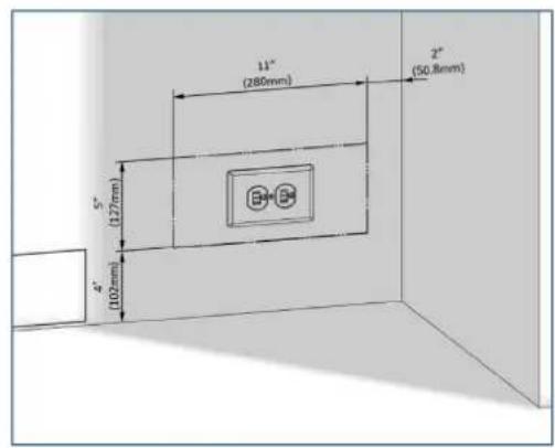
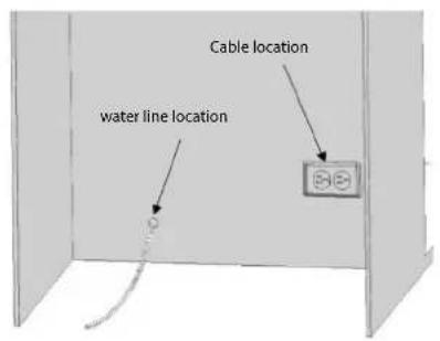
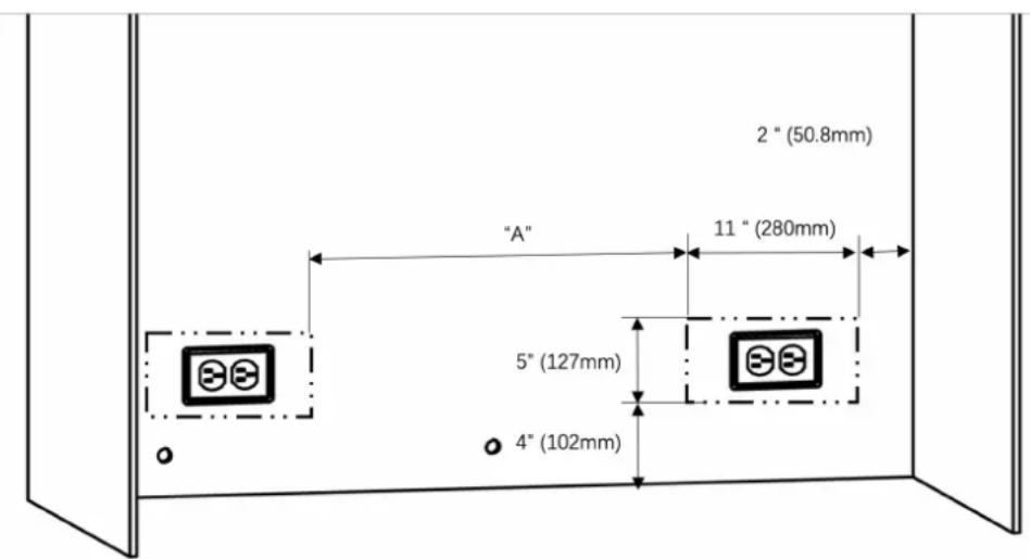
Location of the Electrical Wiring
Location of the electrical wiring must be within the range given below.

ATTENTION
Do not use extension cables or two-pin adaptor and do not remove the ground terminal of the grounding cable..

ATTENTION
A qualified electrician must ensure that the poles of the socket are connected correctly. Verify that the grounding of the socket is correct.
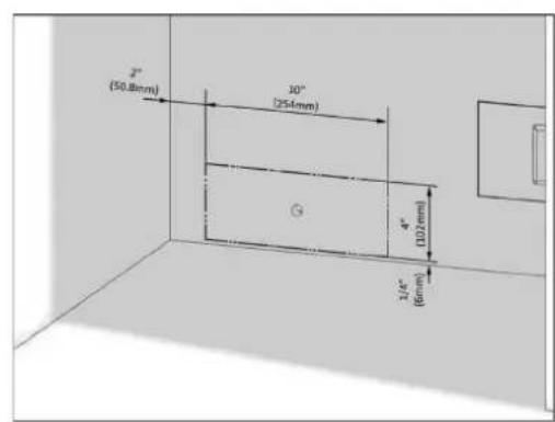
Location of the Water System
The water connected to the appliance must be potable.
Location of the water system must be within the range given below.
Water system of the refrigerator must be connected to the water mains system in the house.
The user must be able to switch it on/off with the valve when necessary.
Objects that might pierce the water hoses or cause them to twist must not be present where the water line is installed.
Pressure of the water system must be between 25-80 psi (1.7-5.5 Bar).
If the water pressure exceeds 80 psi, install a pressure limiting device or water impact protector to the inlet valve. Never install the product or operate the appliance if it is possible for the water pressure to exceed 120 psi.

WARNING
Make sure that there is no water leakage when making the water connections. Otherwise, there will be water on the floor and the furniture will get damaged.
You will need a hose with a minimum length of 60^ (1.5 meters) and a diameter of " for water connections of the product during installation. A connector that has a thread with an external diameter of must be used to connect the hose end to the product.Before completing the installation, make sure that water flows and there is no water leakage.

WARNING
- Flatness of the floor where the product will be installed must be checked with a Bubble Level Tool.
- Uprightness of the furniture flanges must be checked with a Bubble Level Tool.
If the appliance is not level and square, problems may arise with the installation.
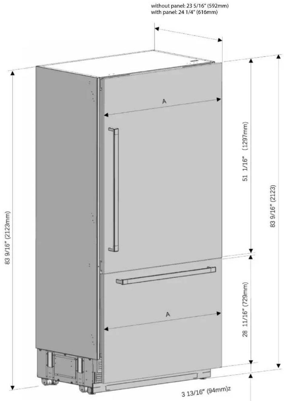
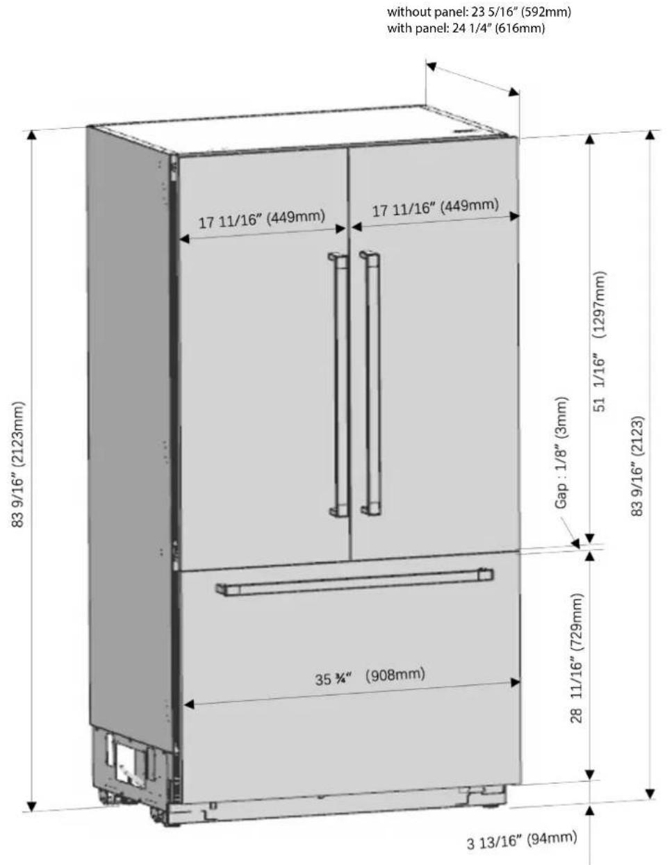
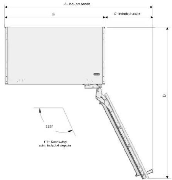
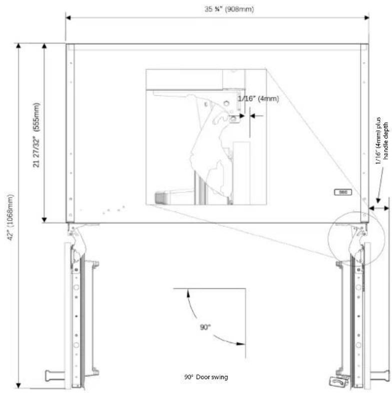
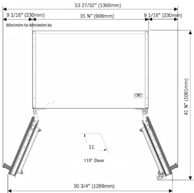
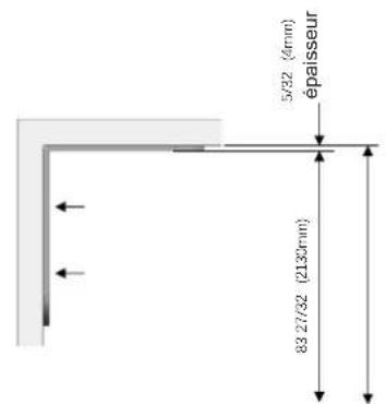
Product dimensions
| Category FM4BM30(I)FBI FM4BM36(I)FBI FM4FBM36(I)FBI | ||
| A 29 3/4" (756mm) 35 3/4" (908mm) 35 3/4" (908mm) |
FM4FBM30(I)FBI
FM4FBM36(I)FBI
Category FM4BM30(I)FBI FM4BM36(I)FBI FM4FBM36(I)FBI
A 159 / 32^ (388mm) 15 9/32" (388mm) 15 9/32" (388mm)
Category FM4BM30(I)FBI FM4BM36(I)FBI
| A 32 7/16" (824mm) | 38 7 | /16" (976mm) |
| B 29 3/4" (756mm) | 35 3 | /4" (908mm) |
| C 55 1/32" (1398mm) | 61" | (1550mm) |
Category FM4BM30(I)FBI FM4BM36(I)FBI
| A | 443/8" (1127mm) | 54 3/4" (1391mm) |
| B 29 | 3/4" (756mm) 35 3/4" (908mm) | |
| C | 14 5/8" (371mm) | 19" (483mm) |
| D | 52 11/16" (1338mm) | 57 11/16" (1466mm) |
FM4FBM36(I)FBI
FM4FBM36(I)FBI
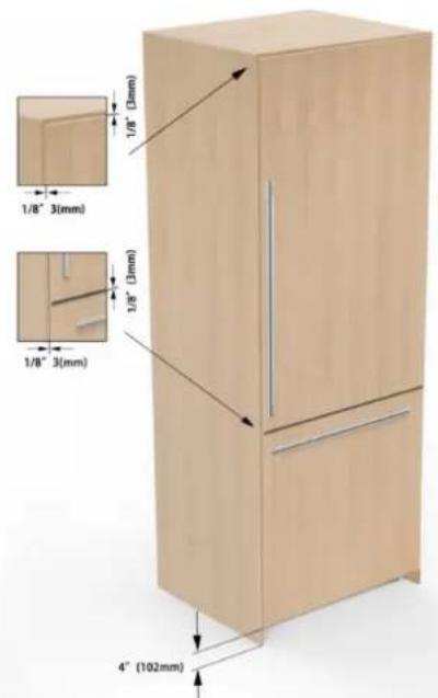
Assembly dimension between Wood panel and fridge door
Assembly dimension between Wood panel and freezer door
FM4BM30(I)FBI-FM4BM36(I)FBI FM4FBM36(I)FBI

EN
| A B C | |||
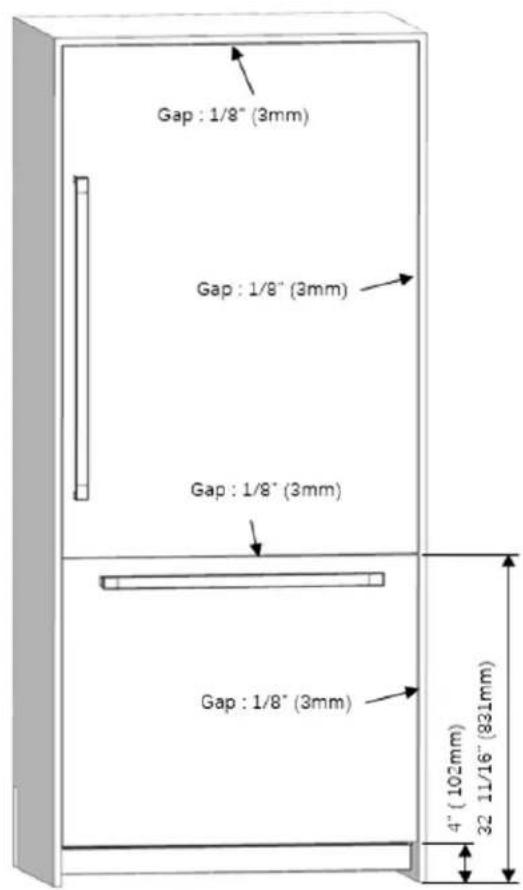
| standard 4" (102mm) 32 11/16" (831mm) | 84" (2134mm) | ||
| minimum 3 13/16"(97mm) 32 1/2" 826mm | 83 13/16" 2129mm | ||
| maximum 5 3/8" 137mm 34 1/8" 866mm | 85 3/8" 2169mm | ||
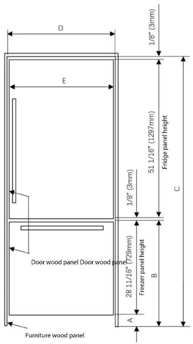
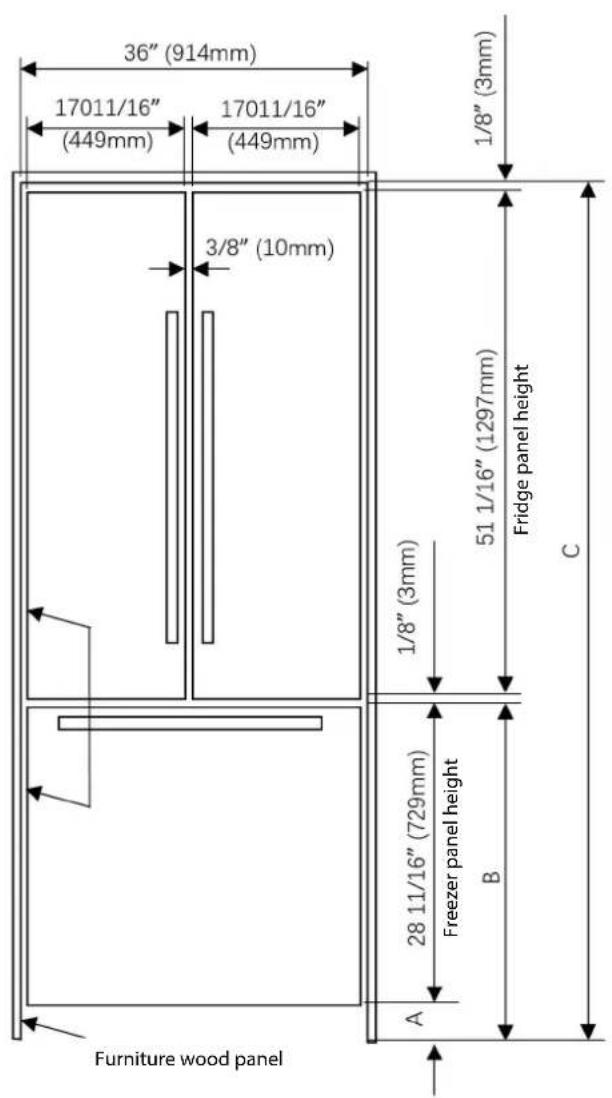
| Category FM4BM30(I)FBI FM4BM36(I)FBI FM4FBM36(I)FBI | |||
| D | 30" (762mm) | 36" (914mm) | 36" (914mm) |
| E | 29 3/4" (756mm) | 35 3/4" (908mm) | 35 3/4" (908mm) |
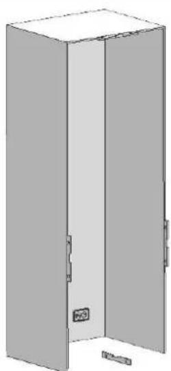
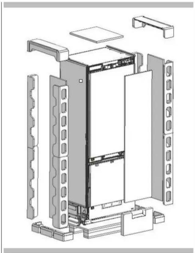
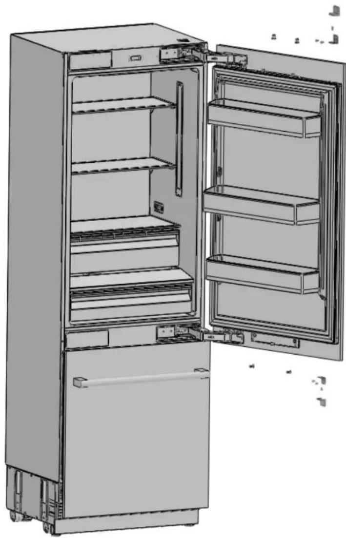
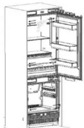
Unpacking

WARNING
At least two persons must carry the refrigerator.


Use a box cutter to remove the tape.
Cut the Packaging Board with a Box Cutter through the section illustrated in dotted lines and remove it.


- Remove the Packaging Polystyrene material.

ATTENTION
Do not remove the tape of the upper door on the product until the refrigerator is placed into the cabinet. Risk of tipping over.
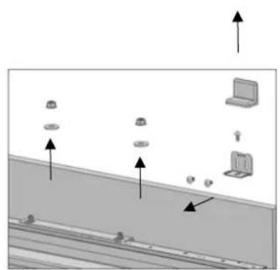
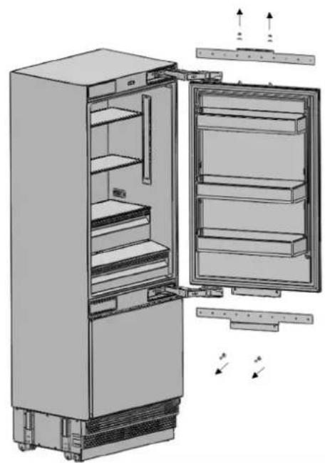
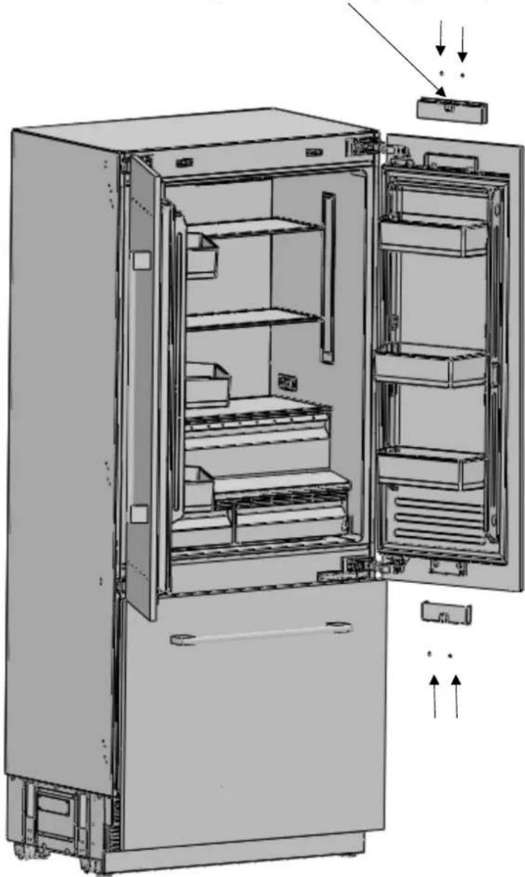
Removing Accessories from the Back
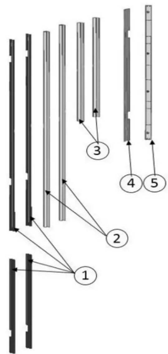
| No Part name spec 30 36 36F | ||||
| 1 Trim fridge furniture side PVC extrusion L=617, | L=1,259 4 4 4 | |||
| 2 Trim fridge door side PVC extrusion L=1136 2 | 2 4 | |||
| 3 Trim freezer door side PVC extrusion L=556 2 | 2 2 | |||
| 4 Trim furniture top PVC extrusion L=762, L=914 | 1 1 1 | |||
| 5 Cover freezer door top abs | 1 1 1 |
Conference
| Category | FM4BM30(I)FBI | FM4BM36(I)FBI | FM4FBM36(I)FBI |
| Abbreviation. | 30 | 36 | 36F |
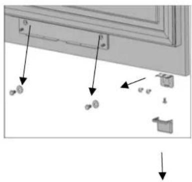
Removing mounting Parts in the Freezer Compartment
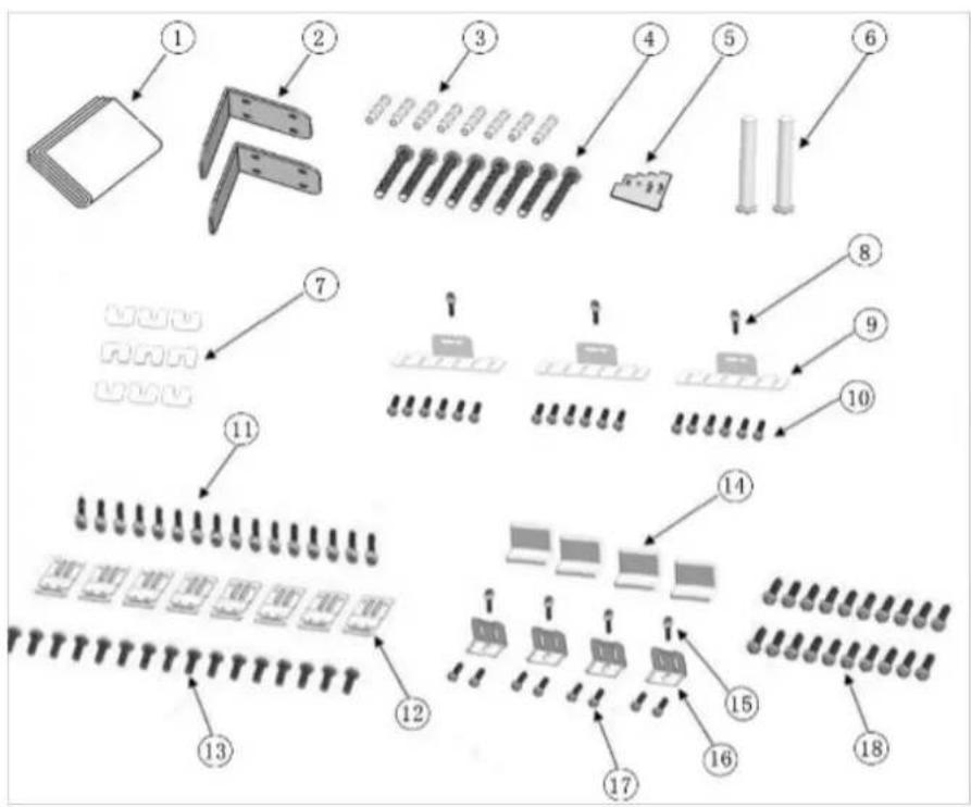
| No Part name spec 30 36 36F | |||||
| 1 | Furniture door preparation template paper 1 1 1 | ||||
| 2 | Anti tip bracket T4.0, Zn-coating 2 2 2 | ||||
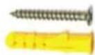
| 3 | Dowel - 8 8 8 | ||||
| 4 | Anti tip bracket screws M8*L60 8 8 8 | ||||
| 5 | Position adjustment jig PS 1 1 1 | ||||
| 6 | 90° limiting pins sus 2 2 - | ||||
| 7 | Freezer furniture door adjustment washer abs 9 9 9 9 9 9 9 9 9 9 9 9 9 9 9 9 9 9 9 9 9 9 9 9 9 9 9 9 9 9 9 9 9 9 9 9 9 9 9 9 9 9 9 9 9 9 9 9 9 9 2 | 9 9 9 9 9 9 9 9 9 9 9 9 9 9 9 9 9 9 9 9 9 9 9 9 9 9 9 9 9 9 9 9 9 9 9 9 9 9 9 9 9 9 9 9 9 9 9 9 9 9 | 3 3 3 3 3 3 3 3 3 3 3 3 3 3 3 3 3 3 3 3 3 3 3 3 3 3 3 3 3 3 3 3 3 3 3 3 3 3 3 3 3 3 3 3 3 3 3 3 3 3 3 | 2 2 2 2 2 2 2 2 2 2 2 2 2 2 2 2 2 2 2 2 2 2 2 2 2 2 2 2 2 2 2 2 2 2 2 2 2 2 2 2 2 2 2 2 2 2 2 2 2 2 2 | - |
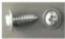
| 8 | Screw freezer door hanger bracket ST4.8*16, round head screw 3 3 3 3 3 3 3 3 3 3 3 3 3 3 3 3 3 3 3 3 3 3 3 3 3 3 3 3 3 3 3 3 3 3 3 3 3 3 3 3 3 3 3 3 3 3 3 3 3 0 | ST4.8*16, round head screw 3 3 3 3 3 3 3 3 3 3 3 3 3 3 3 3 3 3 3 3 3 3 3 3 3 3 3 3 3 3 3 3 3 3 3 3 3 3 3 3 3 3 3 3 0 | 18 18 18 18 18 18 18 18 18 18 18 18 18 18 18 18 18 18 18 18 18 18 18 18 18 18 18 18 18 18 18 18 18 18 0 | ||
| 9 | Freezer door hanger bracket T1.0, Cr+zn-coating 3 3 3 3 3 3 3 3 3 3 3 3 3 3 3 3 3 3 3 3 3 3 3 3 3 3 3 3 3 3 3 3 3 3 3 3 3 3 3 3 3 3 3 3 3 3 3 3 3 4 | ST4x14, counter sunk head screw 18 18 18 18 18 18 18 18 18 18 18 18 18 18 18 18 18 18 18 18 18 18 18 18 18 18 18 18 18 18 18 18 18 | 18 18 18 18 18 18 18 18 18 18 18 18 18 18 18 18 18 18 18 18 18 18 18 18 18 18 18 18 18 18 18 18 18 | 3 3 3 3 3 3 3 3 3 3 3 3 3 3 3 3 3 3 3 3 3 3 3 3 3 3 3 3 3 3 3 3 3 3 3 3 3 3 3 3 3 3 3 3 3 3 3 3 3 0 | |
| 10 | Screw freezer furniture door hanger bracket ST4x14, counter sunk head screw 18 18 18 18 18 18 18 18 18 18 18 18 18 18 18 18 18 18 18 18 18 18 18 18 18 18 18 18 18 18 | M4*12, truss washer head | 16 | 16 | 16 |
| 11 | Screw cabinet connecting bracket | ||||
Conference
| Category | FM4BM30(I)FBI | FM4BM36(I)FBI | FM4FBM36(I)FBI |
| Abbreviation. | 30 | 36 | 36F |
| No Part name spec 76 91 92 | ||||
| 12 Cabinet-cabin connecting bracket paper 8 8 8 | ||||
| 13 Screw cabin connecting bracket T4.0, Zn-coating | 16 16 16 | |||
| 14 Cover furniture door bracket - 4 4 2 | ||||
| 15 Screw door fixing bracket M8*L60 4 4 2 | ||||
| 16 Door-door furniture connecting bracket PS | 4 4 | 2 | ||
| 17 Screw furniture door fixing bracket sus | 8 8 | 4 | ||
| 18 Screw furniture door hanger bracket | M4*12, truss washer head | 20 | 20 | 24 |
- Anti tip bracket screws
- dowels
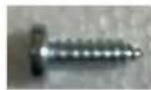
Truss washer head screw Spec:M4x12 Fixing Refrigerator Such as cabinet and door (press part)
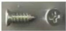
- Counter sunk head screw
- Spec: ST4x14
- Fixing the cabin and furniture door (wood part) and door (press part)
- Round head screw
- Spec: ST 4.8x16
- Fixing freezer
- door top part and
- furniture door (press part)
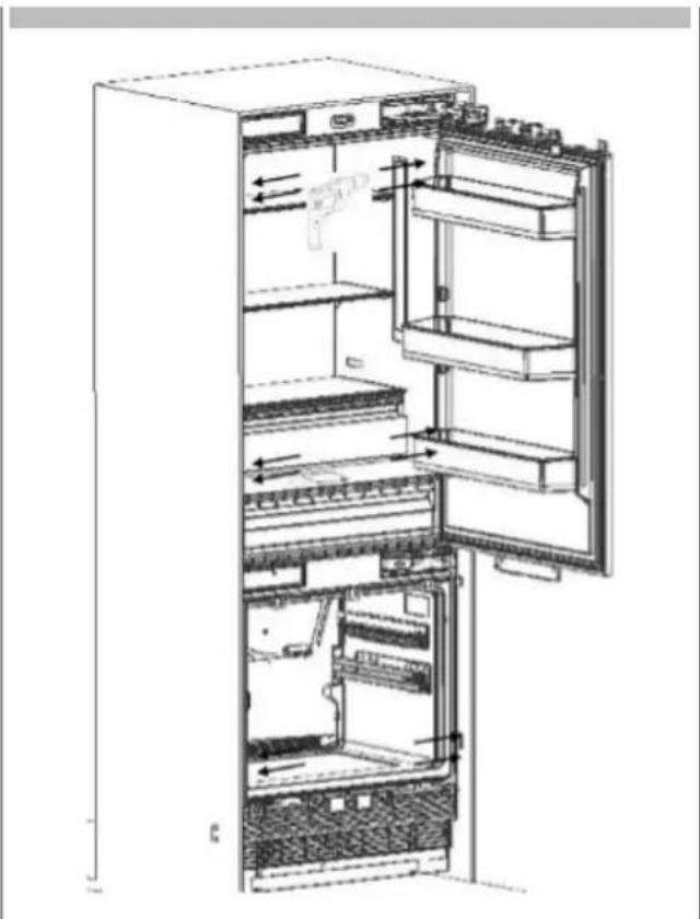
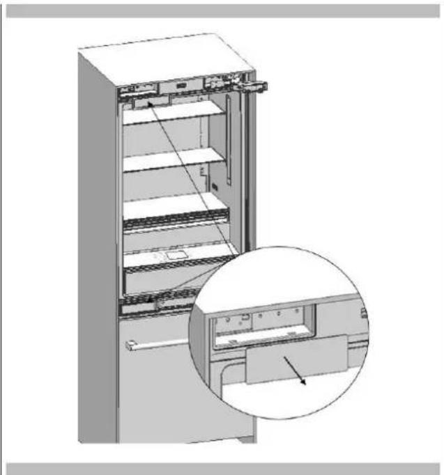
Removing the Freeze Printer Bin
- Remove it manually with 4 knurled screws.
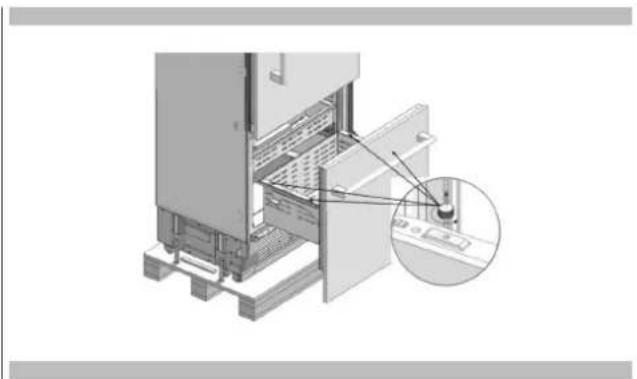
- Remove the Lower Bin.
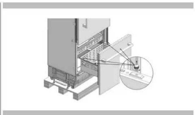
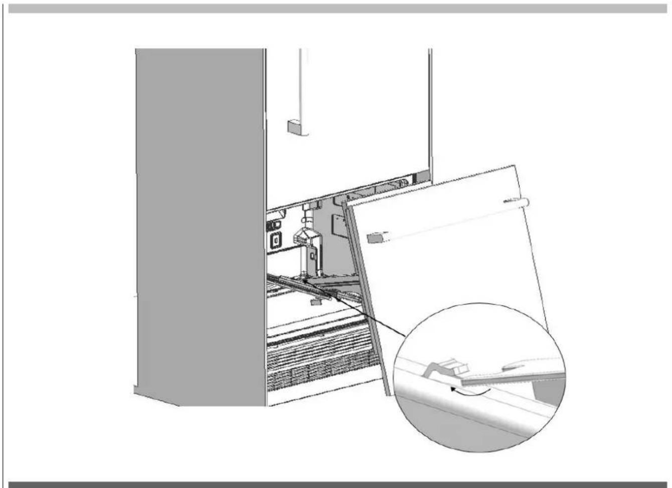
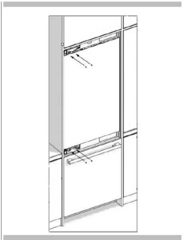
Removing the Freezing Printer
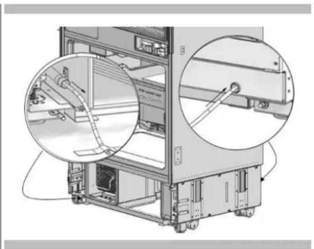
Remove 2 screws which are near the front section and connect the freezing door and the rail.

Pull the door frontward to free it from the tabs at the back and remove it.

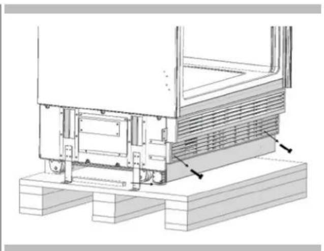
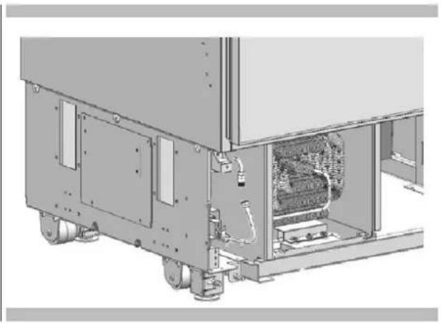
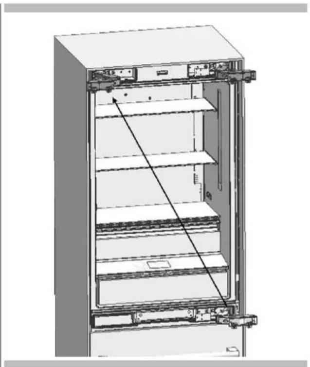
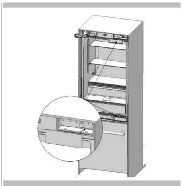
Removing the Lower Ventilation Assembly
- Remove the 2 screws to take out the Lower Vent Hole Assembly.

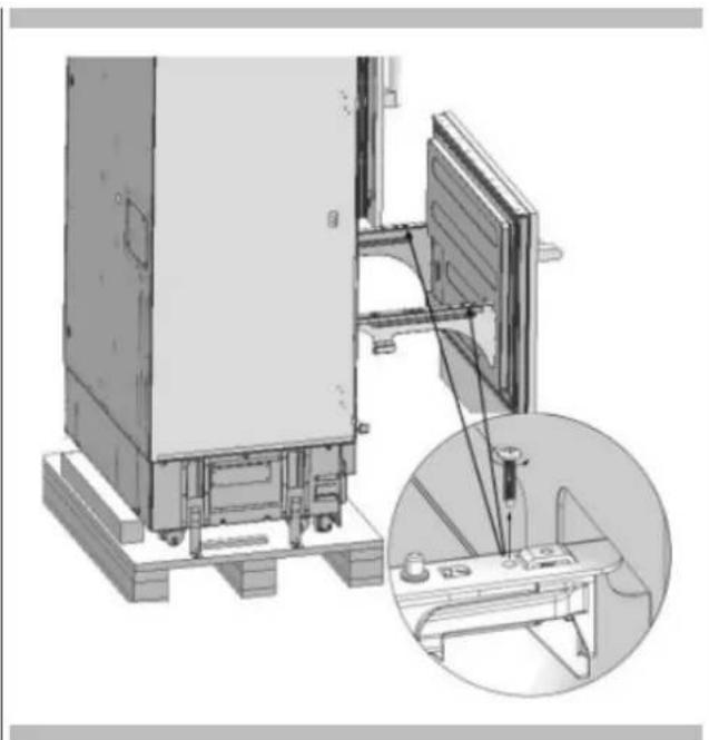
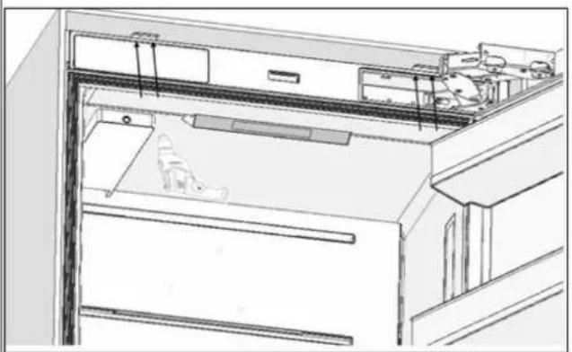
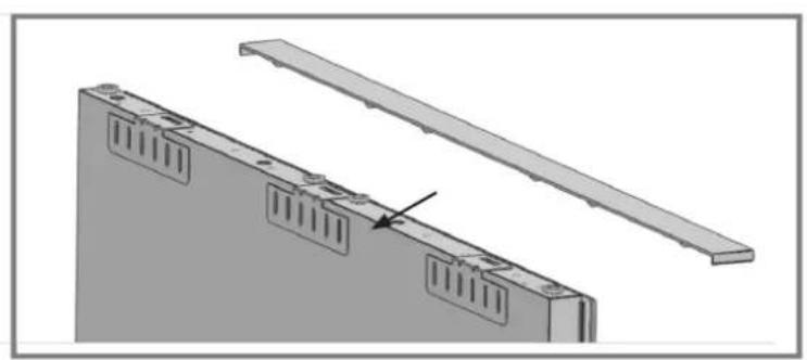
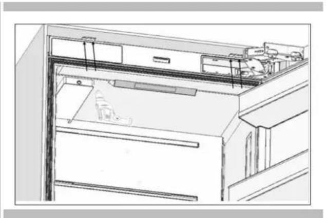
Removing the Upper Ventilation Part
- Remove the 2 screws to take out the Upper Vent Hole Part.
Continue to install the product according to the instructions below. Additionally, consider national and local instructions regarding installation.
Please observe the following:
- For the USA, The National Electrical Code, ANSI/NFPA 70 - last version/State or Municipality directives and/or regional directives.
For Canada, The Canadian Electrical Code, C22.1 version/State or Municipality directives and/or regional directives.
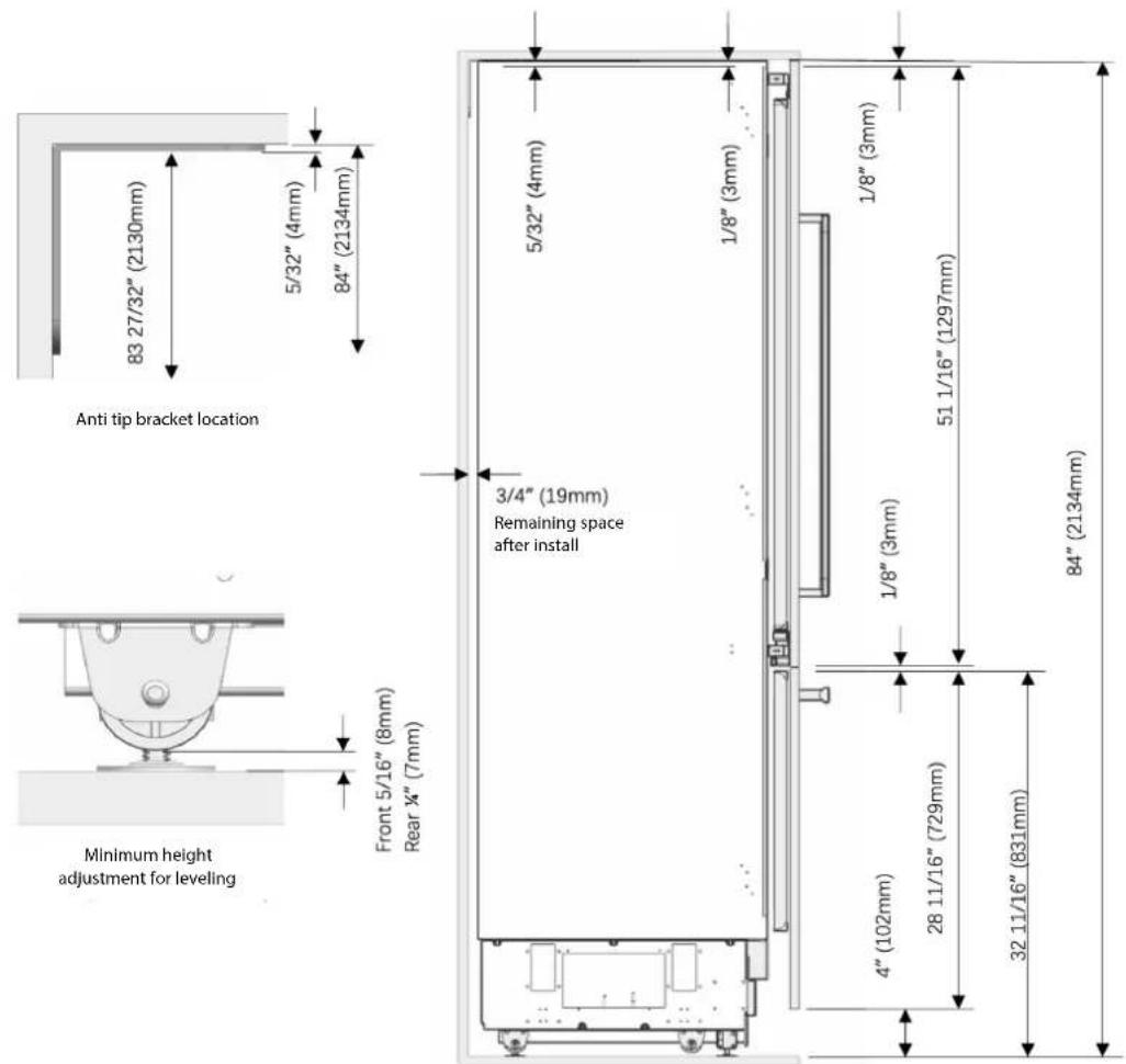
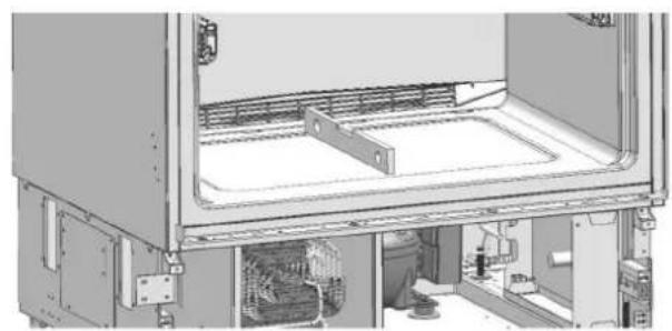
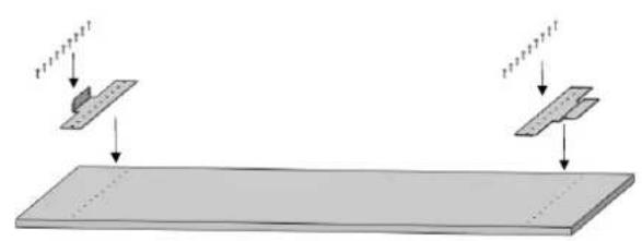
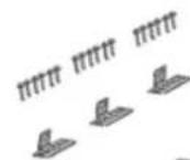
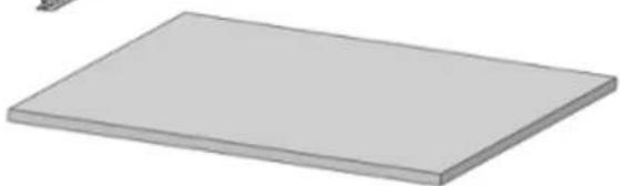
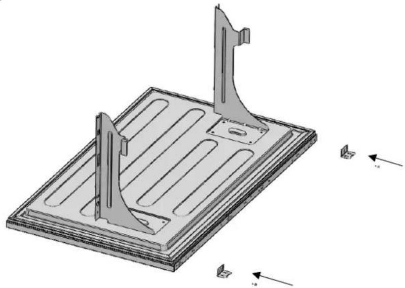
Mounting the Anti-Tip Brackets

WARNING
You must definitely use anti-tip brackets to prevent the appliance from tipping over in absence of connecting to a secured cabinet. Using them in addition to securing to the cabinet, increases security.

WARNING
Make sure that there is no electrical or water connection where the screws will be tightened, and connections will be established.

WARNING
Please remember to use the necessary protective equipment when drilling holes in the wall and performing installation.
Mark the wall for Anti-Tip Brackets (item No.2).

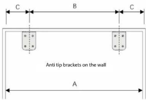
| Category | FM4BM30(I)FBI | FM4BM36(I)FBI | FM4F | BM36(I)FBI |
| A 30" | (762mm) | 36" (914mm) | 36" (914mm) | |
| B | 23 5/8" (600mm) | 23 5/8" (600mm) | 23 5/8" (600mm) | |
| C | 3 3/16" (81mm) | 6 3/16" (157mm) | 6 3/16" (157mm) | |
last
- Use a drill to create holes for dowels (item No.3) at the marked points. (5 / 16^ - 08)

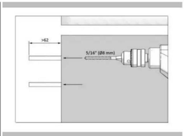
Use the hammer to fit the dowels (item No.3)

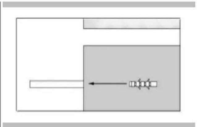
- Fit the anti-tip brackets (item No.2) into their places, using 4 screws (item No.4) for each. You must use both the (2) brackets to ensure the safety of the product.

Preparing the Water Hose and the Power Plug
You will need a hose with a minimum length of 60^ (1.5 meters) and a diameter of 1 / 2^ for water connections of the product during installation. A connector that has a thread with an external diameter of must be used to connect the hose end to the product. You can choose the method A or method B below to prevent the cable from getting jammed.

WARNING
If you are not sure whether the existing connection parts are fit to the wall as securely as they should be, you can use alternative anti-tip methods.
If there is furniture at the back wall of the refrigerator, please make sure that the furniture is fixed to the wall. For this, you need to be sure that the back wall of the furniture is fixed to the concrete back wall or to a wooden stud with suitable fasteners.
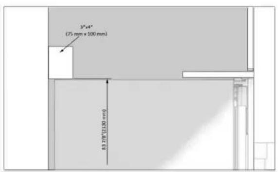
Alternative anti-tip method
If the anti-tip brackets cannot be connected securely, you must use the alternative method below. In this method, you can use wooden blocking to avoid the risk of tipping over. It must be installed as illustrated in the figure below.
There must be no clearance between the product and the wooden blocking.
Minimum section dimensions of the blocking must be 3'' × 4'' (75 mm × 100 mm). The width of the blocking must be equal to the clearance where it will be installed.
An additional block must be used if the niche depth is more than anticipated. The blocking must contact the product with a contact of 2^ (50.8 mm).
To determine the location for the blocking, mark it on the rear wall, select suitable screws and connect safely.

WARNING
The number and features of the screws to be used for the blocking must be determined so that there is a secure connection.
Method B:Locate the water hose and power supply on the side.
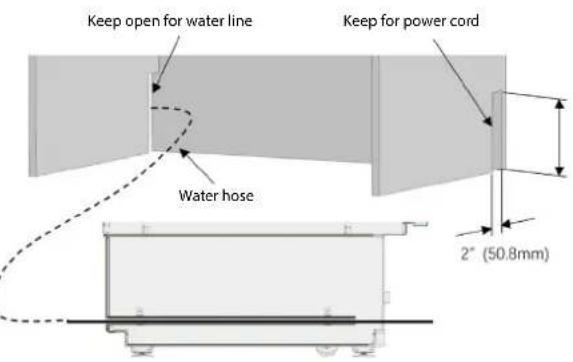
Utilize the factory installed pass-through tube to feed the waterline through to the front where the connection to the valves will be made.
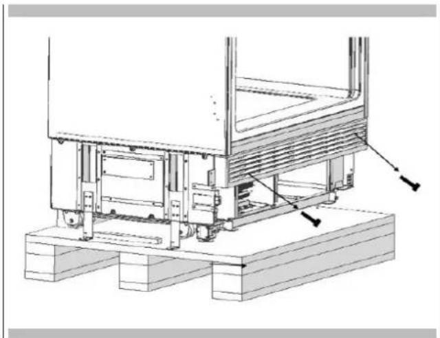
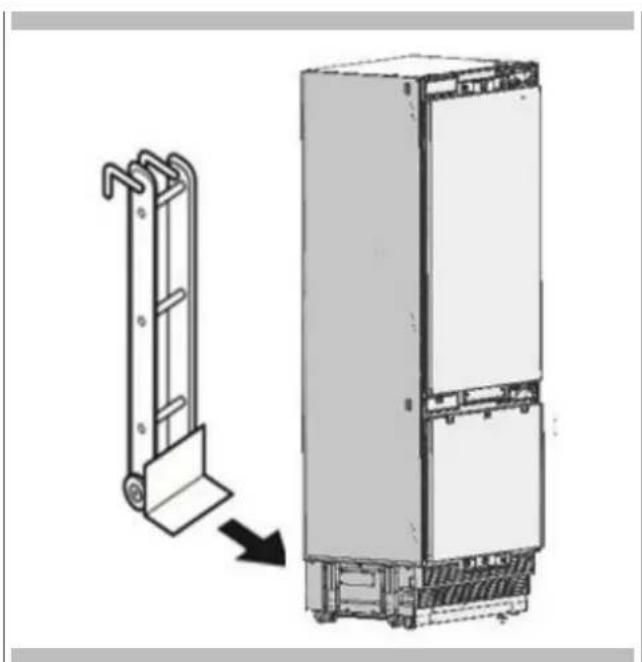
Taking the Refrigerator from the Wooden Pallet
- Remove the brackets that connect the refrigerator to the Wooden Pallet.

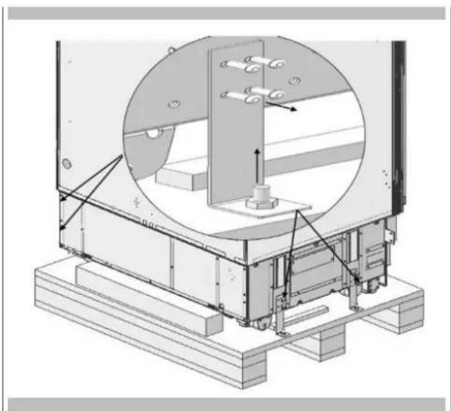
- Recline the refrigerator slowly and pull back with the help of the cart, and then land it.


ATTENTION
The risk of tipping over is high as of this point. You should not open the doors until the product is placed into the cabinet.
Placing the Refrigerator into the Cabinet
- Insert the waterline into the tube at the back and take it out from the front.

IMPORTANT INFORMATION
- Apply the below method to prevent the cable from getting jammed.
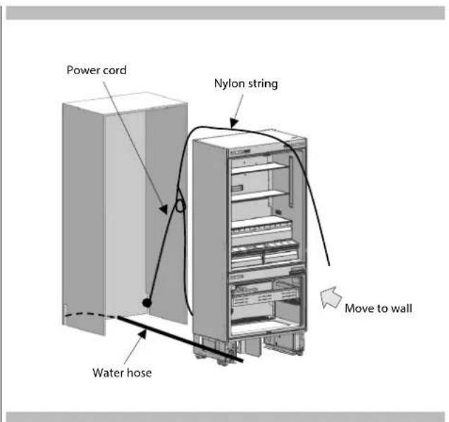
- Start the refrigerator and make sure it has power. (You can check if the lights in the freezer compartment are on or off to see if the product is operating).

IMPORTANT INFORMATION
You can use masking tape and similar protectors on parts you think this is necessary to protect the edges of the furniture when placing the product.

WARNING
The plug of the product must be accessible after installation. If the plug is not accessible after installation, the power must be cut off from the circuit breaker.

WARNING
Make sure that the mains cable is not pinched when placing the product.
- Push the product carefully towards the cabin to place it. If there is strain during the placement of the product into the cabin:
- The floor might be rough or uneven.
- Adjustable feet might be loose. (please see the relevant section to learn how to adjust the adjustable feet)
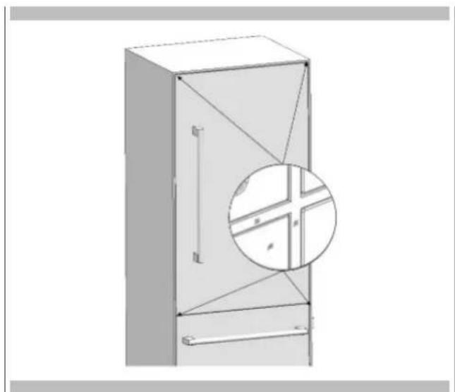
- You must attach the freezer door temporarily to align the product before placing it.

IMPORTANT INFORMATION
You must use the upper edges of the freezer door when aligning the product with the furniture. Adjustment of other edges are explained in the following pages.
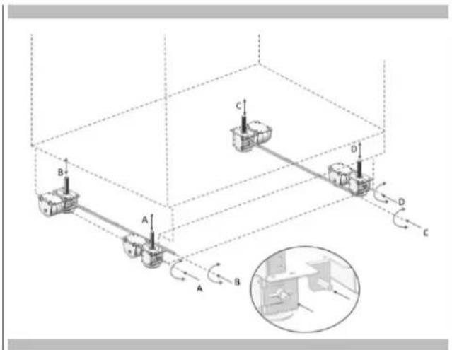
Adjusting the Height of the Refrigerator in the Cabinet
- Adjust the refrigerator height using the adjustable feet.


WARNING
Start with raising the front feet first (before the back feet) to reduce the risk of the appliance falling frontward.
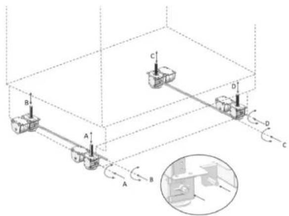
A/D -Turn the key clockwise to lift the front. B/C -Turn the key clockwise to lift the rear.
After adjusting the adjustable feet, check the level in both width and depth directions.
The maximum height that the adjustable feet can reach is 1 9 / 16^ (40 mm) and the product height is 853 / 8'' (2,169 mm)

IMPORTANT INFORMATION
Adjusting the Appliance with Respect to the Side Walls
- For products with overlay panels in place, the position of the appliance is adjusted so that the door and the furniture surfaces are flush. You can also use position adjustment jig (Item No5) if necessary.
- For products without overlay panels in place already, the product is placed using the adjustment part (Item No5) as shown in the figure below.

IMPORTANT INFORMATION
It is very important to align the upper edge of the freezer door when aligning, as its position is fixed and all other panels can be adjusted with respect to it. All the other edges can be adjusted with the adjustment mechanisms.
- For products without overlay panels in place already, the product is placed using the adjustment part (Item No5) as shown in the figure below.
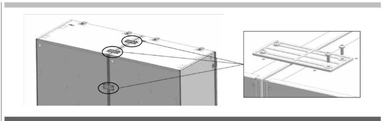
Attaching the Cabinet Connection Brackets
Fix the cabinet connection brackets (Item No12) to the appliance, where: 2 on the top, and 3 on each side. Use screw cabinet connecting bracket (Item No11) to tighten.
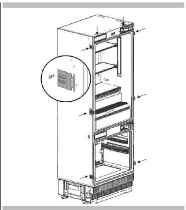

WARNING
Before starting to screw the side and upper brackets, please make sure that water is supplied to the product and there is no water leakage.
i IMPORTANT INFORMATION
If you have difficulty tightening the screws, opening a reference hole with the drill will make this procedure easier.
- Attach cabinet connection brackets (Item No12) to the cabinet with 16 screws cabin connecting bracket (Item No13).

EN 8 - Installation at the bottom
Water connection
- Use the box cutter to cut the water hose squarely from the end of the pass-through tube, leaving a section of 10^ .


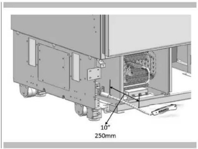
- Use the 2 wrenches to firmly connect the hose coming from the mains and the hose coming from the valve.

WARNING
The hose coming from the mains must be one piece. Do not use extension hoses.

WARNING
Make sure that the power is cut off when making the water connection of the product.

WARNING
The water valve must be off when connecting the water hose.

WARNING
It is recommended that the water on/off valve remains accessible after installing the product.

WARNING
This product is suitable for use with cold water mains only.

WARNING
Pressure of the water system must be between 25-80 psi (1.7-5.5 Bar).

IMPORTANT INFORMATION
Once the connection is complete, you must turn on the mains valve and make sure that there is no leakage at that point.
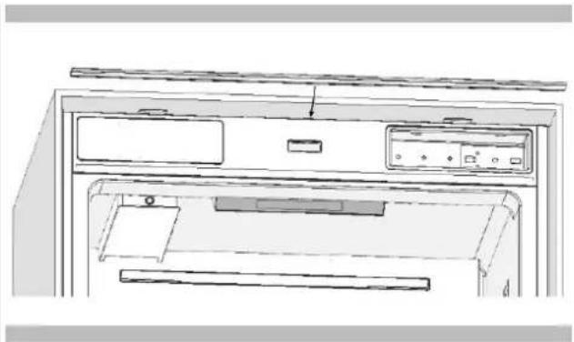
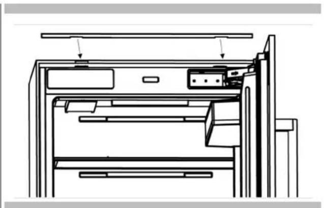
Attaching the Upper Ventilation Part
Use 2 screws to attach the upper vent hole part.

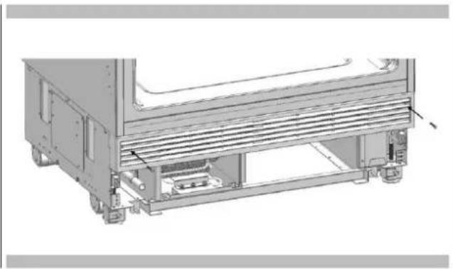
Attaching the Lower Ventilation Assembly
Use 2 screws to attach the lower ventilation part.


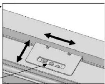
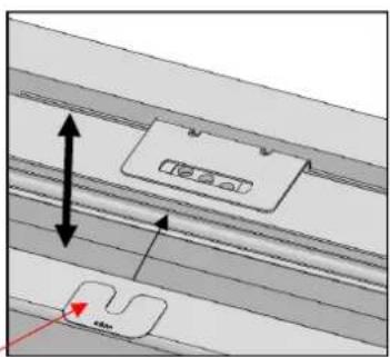
IMPORTANT INFORMATION
You can move the lower vent hole ventilation part to adjust it to the kick plate in the kitchen.

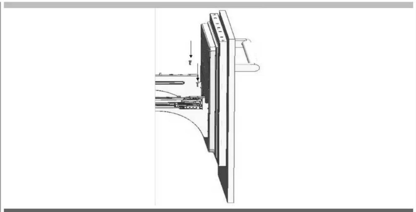
WARNING
Forward-backward travel distance of the lower kick plate can be 15 / 16^ (23 mm). As you can see in the figure, the decorative kick plate must not be in front of the upper vent hole level.
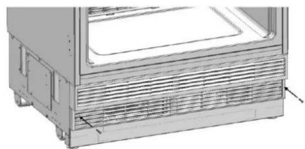
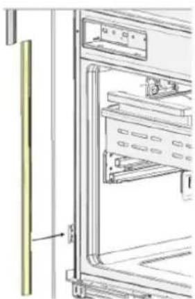
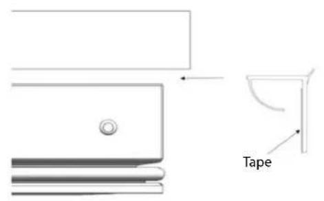
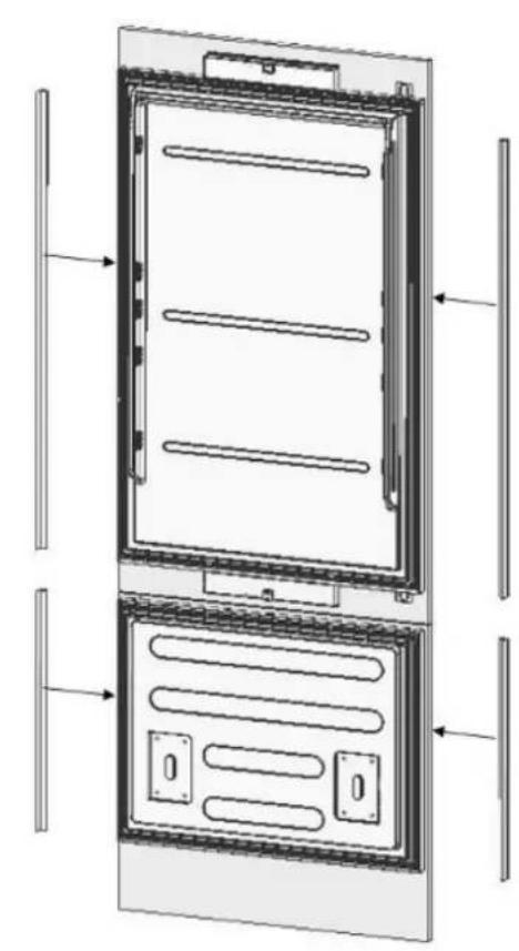
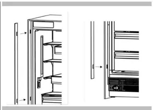
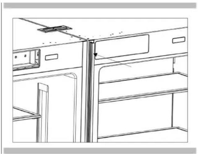
Attaching the Decorative Trim Parts
- Attach the trim fridge furniture side (Item No1) onto cabinet-cabin connecting bracket (Item No12).
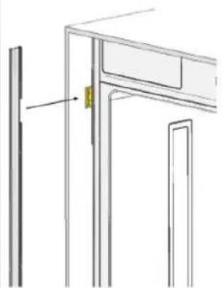
- Attach the trim furniture top (Item No4) over top cabinet connection bracket (Item No12).

WARNING
Maximum weights of the door overlay panels to be mounted to the product are as follows. Fridge Door: 35.7 lbs. (16.2 kg)
Freezer Door: 19.8 lbs. (9 kg)
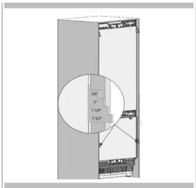
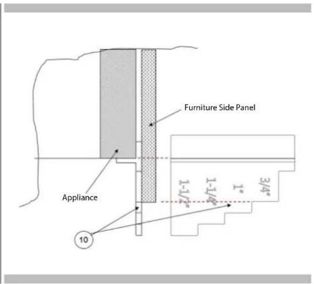
Choosing the Door Thickness
If the door thickness is more than 1 12 opening must be limited to 90. You must use a limiting pin on the hinge (included).
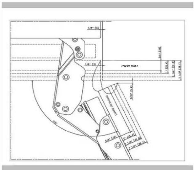
- You can limit the opening degree of your door to 90 if you want. In this case, the door thickness levels can be like the following (you can look at the relevant section to learn how to attach the 90 limiting pin (Item No6).
90^ limit pin should be inserted to upper hinge and lower hinge
This section contains information about preparing the door overlay panels and mounting them to the product.
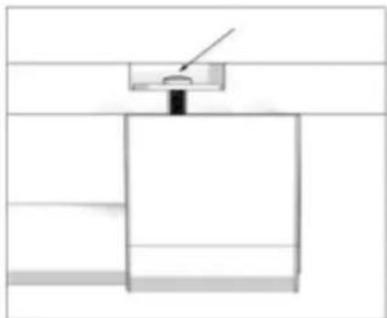
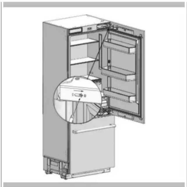
Removing the Mechanism Covers
- Remove screws to take off the upper bracket cover and fixing bracket.

IMPORTANT: There is a magnet inserted into this cover that is necessary for the appliance to detect when the door is closed. Ensure this cover with magnet is replaced when completing the installation.

- Remove two screws to take off the lower bracket cover.

Removing the Panel-Adjustment Mechanisms on the Refrigerator
- Remove the upper and lower Adjusting Mechanism assemblies from the door.
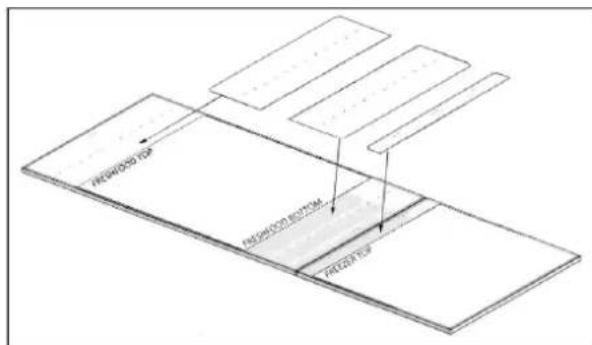
Preparing the Door Overlay Panelst

IMPORTANT INFORMATION
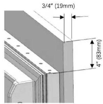
You must take the dimensions into account when grouping the bracket parts on the furniture doors. When marking, you can use the "Furniture door preparation (Item No 1) provided with the product.
templ

WARNING
Handle connection holes must be adjusted according to the handles to be used in kitchen design.

WARNING
Minimum thickness of the door must be " (19mm).
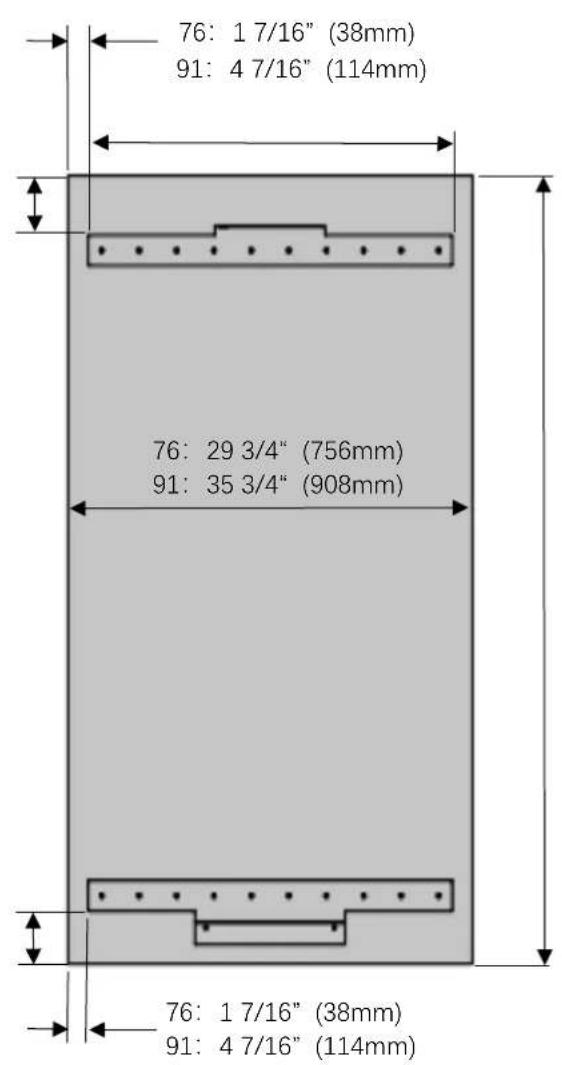
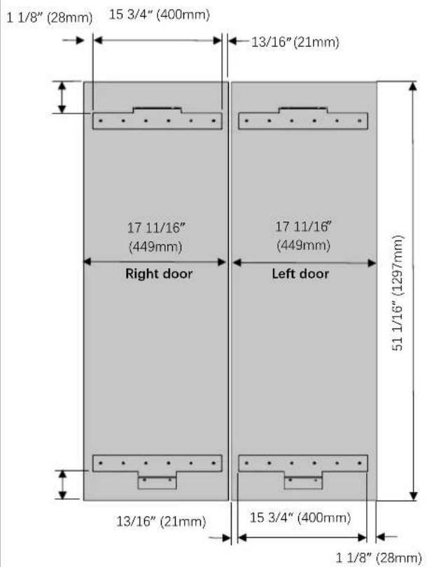
Preparing the Fridge Door Overlay Panel
FM4BM30(I)FBI - FM4BM36(I)FBI
FM4BM36(I)FBI

WARNING
You must use screws suitable for the door thickness.
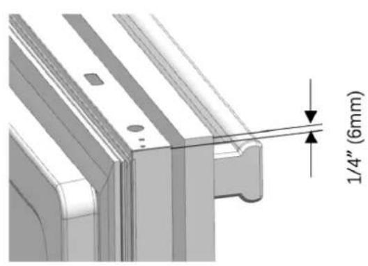
- Install the two hanger brackets using the provided screws (Item No18). You can also use the furniture door preparation template (Item No 1) provided with the product to align these parts. It is recommended to keep this template for future reference.
FM4BM30(I)FBI-FM4BM36(I)FBI

FM4BM36(I)FBI
- Attach the fridge door handle.
Depending on the style of screw you may need to countersink. The screw head must not protrude.
Preparing the Freezer Door Overlay Panel
Handle connection holes must be adjusted according to the handles to be used in kitchen design.

WARNING
Minimum thickness of the door must be " (19 mm).

WARNING
You must use screws suitable for the door overlay panel thickness.
- Attach freezer door hanger brackets (Item No9) using 6 screws (Item No18) for each.

- Attach the fridge door handle.
Depending on the style of screw you may need to countersink. The screw head must not protrude.
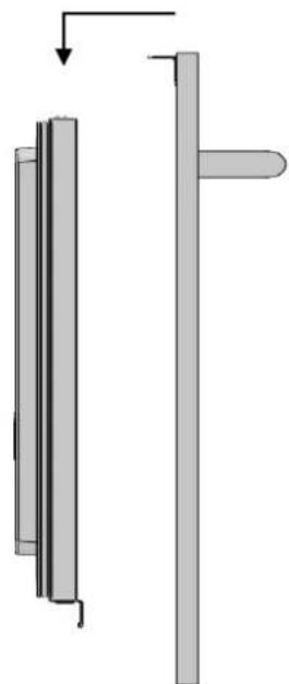
Installing the fridge door overlay
- Attach the fridge door overlay panel to the fridge door.
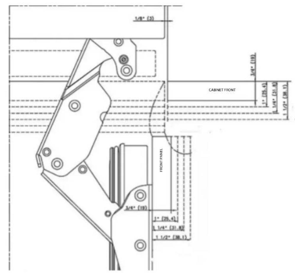
How to align the fridge door with bolts
Position of the door overlay panel to the kitchen cabinets must be flush.
To achieve this, you should adjust 3D direction using by two fixing bolt to perform fine adjustments.
Before you begin, review the position of the door overlay panels with respect to the adjacent cabinets.
Distances between door overlay panels must be 1 / 8'' (3 mm), assuming that the panel dimensions are correct.
You can make door adjustments based on this distance.
How to align the door overlay upper part with bolts.
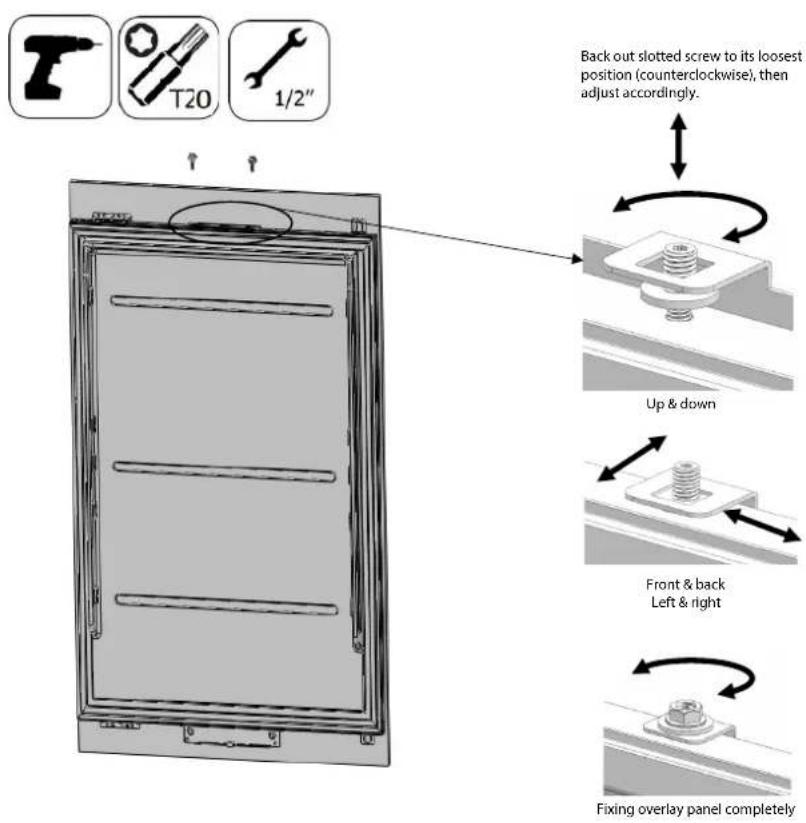
How to align the door overlay panel lower section with bolts.

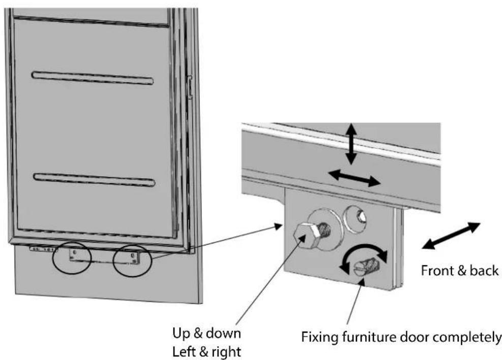
Use the set screws to position the panel in the Z (depth) direction then fix in place firmly with the washers and bolts removed in the earlier steps. Do not over-tighten as it will bend the brackets.
Once you are satisfied with the panel positioning - finally fix the door overlay panel with the provided brackets shown below. This gives additional strength to the handle side where most of the pulling pressure is applied to the door overlay panel.
- Use the door overlay panel connecting bracket (Item No16) to join the furniture door.
- Use 1 screw door fixing bracket (Item No15) to fix on the door.
- Use 2 screws (Item No17) to fix on the door overlay panel.


FM4BM30(I)FBI-FM4FBM36(I)FBI
- Snap on the door bracket covers. (Item No14).
FM4BM30(1)FBI-FM4FBM36(1)FBI
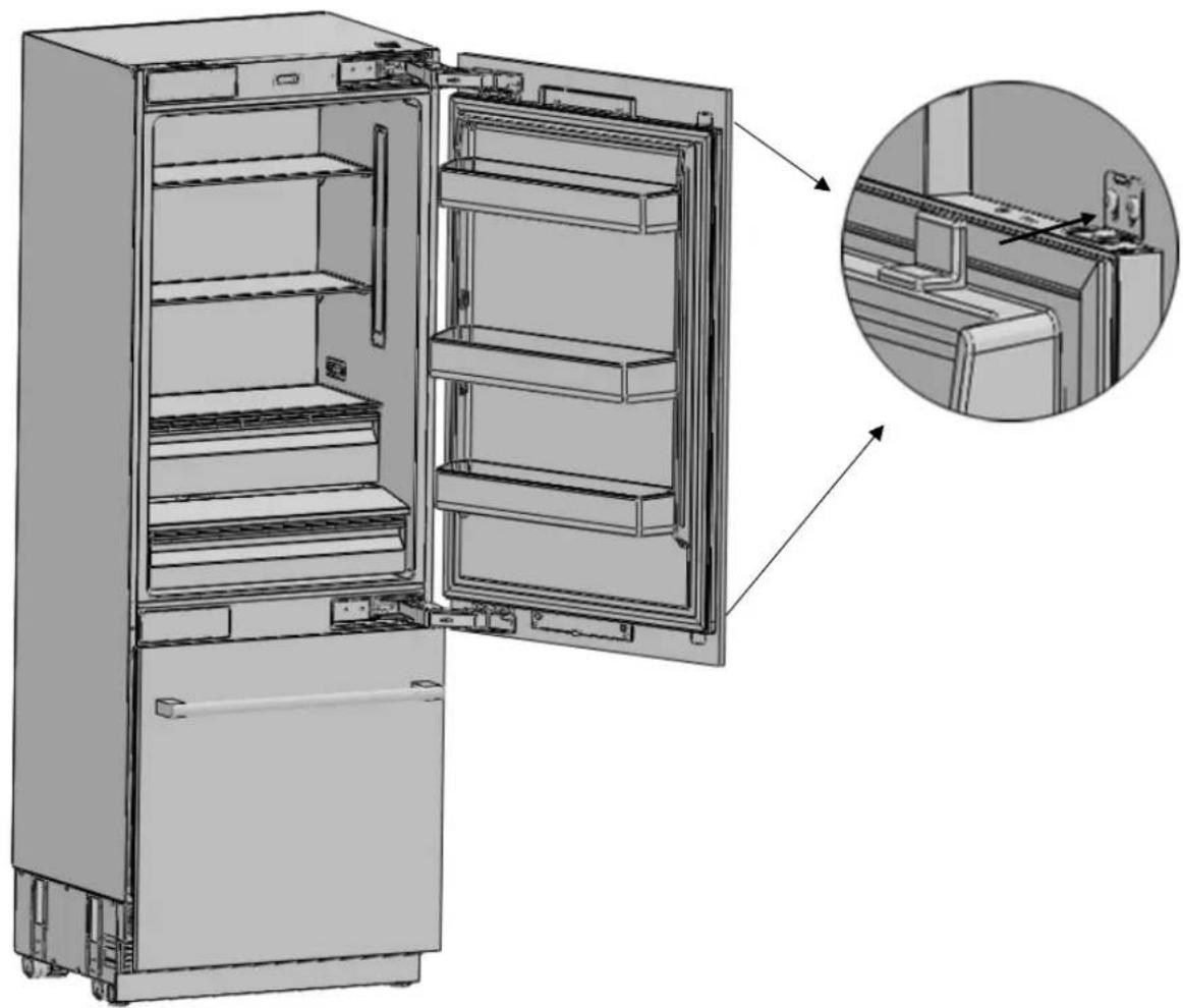
- Snap on the bracket covers.
FM4BM30(I)FBI-FM4FBM36(I)FBI
IMPORTANT: Ensure the upper cover contains a magnet to detect door opening / closing.

WARNING
There is a magnet on the cover door hanger bracket upper. This is a functional part for the operation of the product. It should not be confused with the lower cover.
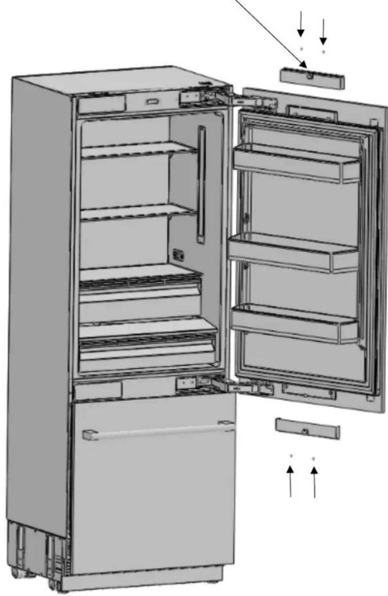
- Attach and screw the upper/lower decoration cover.
FM4FBM36(I)FBI
IMPORTANT: Ensure the upper cover contains a magnet to detect door opening / closing.

WARNING
There is a magnet on the cover door hanger bracket upper. This is a functional part for the operation of the product. It should not be confused with the lower cover.
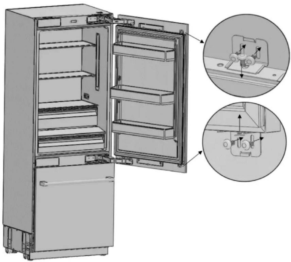
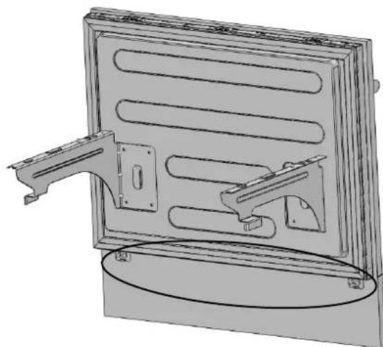
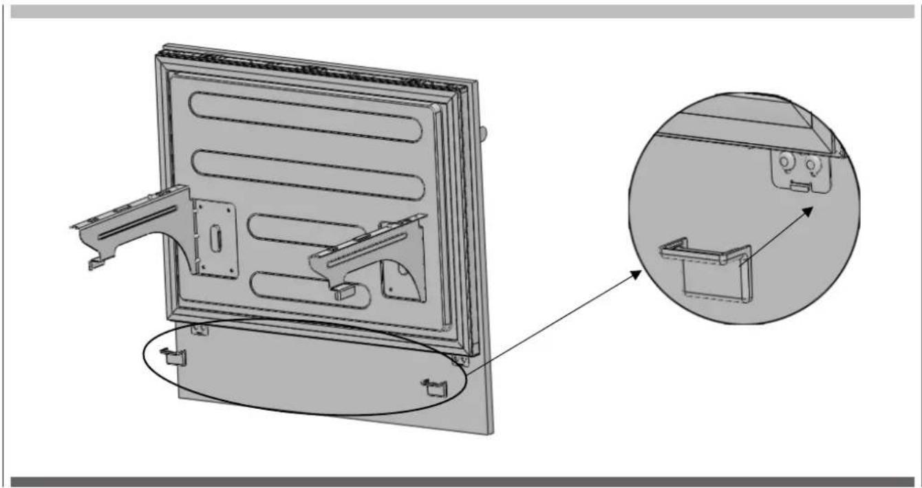
Installing the freezer door overlay panel
- Attach door overlay panel connecting bracket (Item No16) on the door lower section with screw door fixing bracket (Item No15).

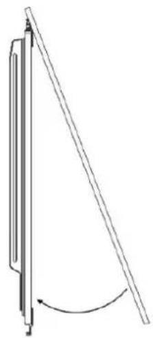
- Attach the door overlay panel to the freezing door

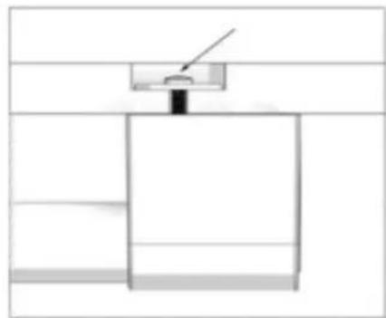
How to align the freezing door overlay panel to the lower section
- How to align the freezer door overlay panel upper part with screw freezer door hanger bracket (Item No8).
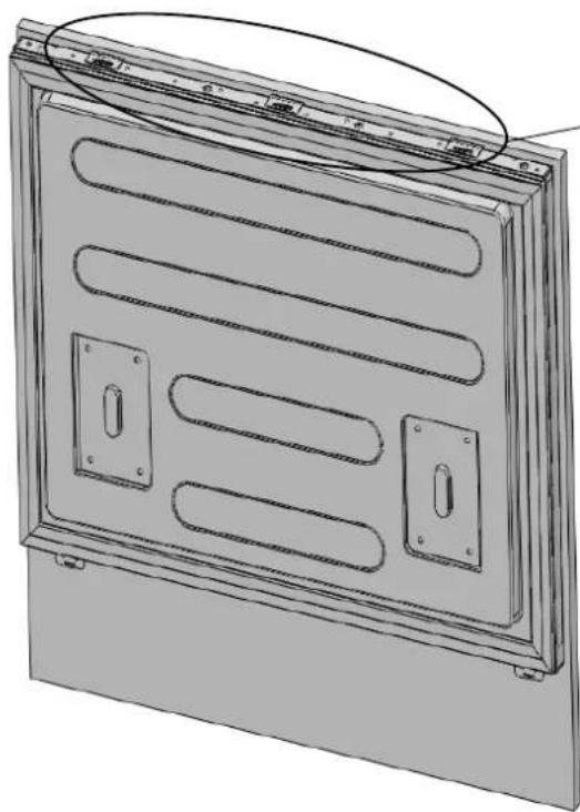
Use the corresponding screw hole that will position the ideal depth of the panel
Front & back Left & right
Up & down
If there is gap between bracket and foaming door, this plastic shim can be used to fill the space.
- Use the door overlay panel connecting bracket (Item No16) to join the freezer door overlay panel.
- Use 2 screws (Item No17) to secure the door overlay panel.

EN
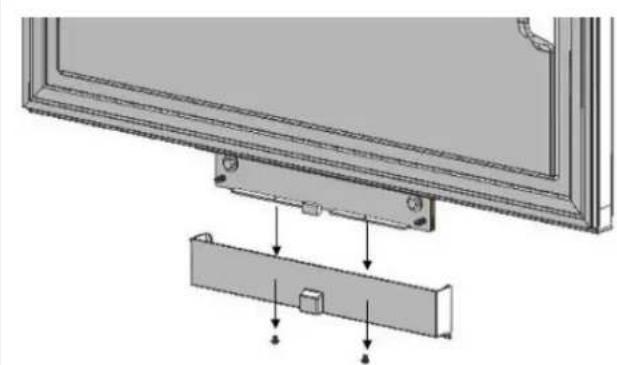
- Clip the door overlay panel bracket cover onto the brackets (Item No 14).
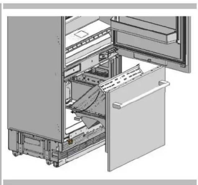
Install the complete freezer door assembly onto the rails.
Once the freezer door assembly is in place, secure to the drawer rails with 2 screws.

- Locate the drawer onto the rail and tighten the screws.
EN
- Snap the freezer drawer cover strip (Item No5) onto the buttons on top of the freezer drawer. It should fit tightly against the overlay panel.
Install the complete freezer door assembly onto the rails.
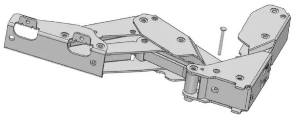
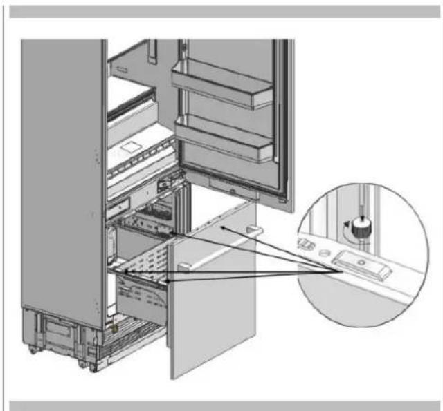
Adjusting the strength of the hinges
- Use a drill to adjust the strength of the close assist of the upper and lower hinges of the fridge door. Set the hinge adjustment screw to position "1" from position "0".

0 = Weakest setting
I = Strongest setting
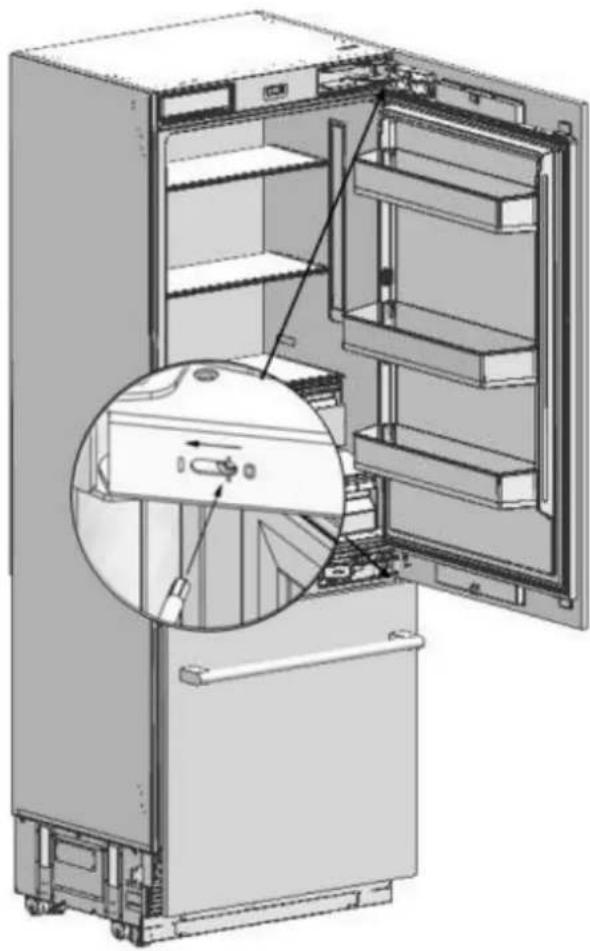

WARNING
The door must be fully open during this adjustment.

WARNING
This hinge adjustment must definitely be performed after the door has been adjusted.
EN 11 - Changing swing of the fridge door
Removing the fridge door
- Set the hardness level of the hinge to "0".

ATTENTION
Failure to set the hinge to "0" and continuing installation like that may cause injury.
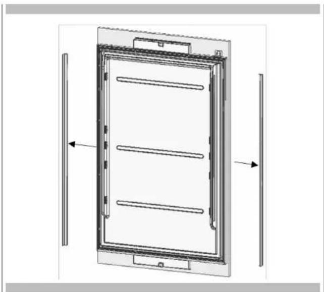
- Remove the side trims.
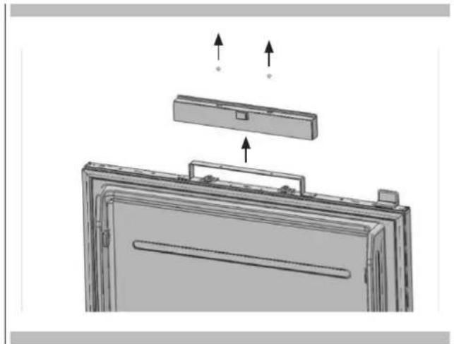
- Loosen 2 screws of the upper cover of the fridge door and remove it.
- Remove the upper adjustment kits.

- Loosen 2 screws of the lower cover of the fridge door and remove it.

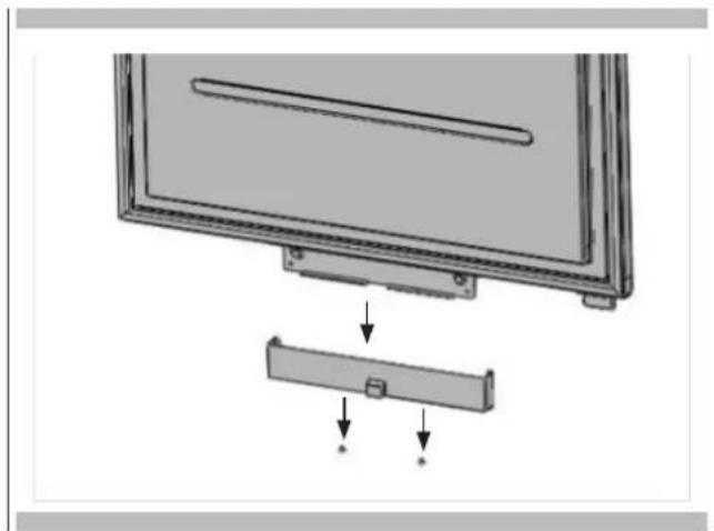
- Remove fridge lower and upper bracket and fixing screws.

FM4BM30(I)FBI-FM4FBM36(I)FBI


WARNING
The clad door will be released when these screws are removed. You must take measures to prevent the door from falling. You can tape the Furniture Door to the Inner Door or ask for help from another person.
Take the Fridge Furniture Door and lay it down on a table upside down.
- You must attach the Furniture Door by rotating it 180 based on its current position.
Removing and preparing the Fridge Inner Door
- Remove the hinge connection screws of the Hinge Brackets.


ATTENTION
The appliance door will be released when these screws are removed. You must take measures to prevent the door from falling.

Take out the fridge door and lay it down on a table remove the fixing parts and screw them to the opposite side of the door as shown figure.


Replacing the hinges
- Remove the Hinge Caps located at the other side where you will fix the hinges.
- Remove the lower right hinge by loosening its 2 screws and fix it to its slot at the upper left side.

- Attach the hinge slot caps removed from the left side to the hinge caps at the right side.
Installing the Fridge Door
- Place the Fridge Door to the refrigerator and fix it with 4 screws.

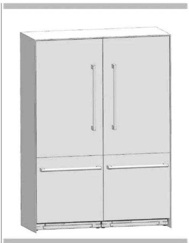
If you are going to make a dual installation, you must use the FM4JOINKIT installation kit. Available from your dealer. The instructions below have been prepared according to Built-in type.
Built-in: Overlay panels for a flush finish with adjacent cabinetry. This is the most common installation scenario.
Cabinet Dimensions
Cabinet dimensions below must be checked before starting the installation.
Dual opening dimension
| Category | 30''+30''(76+76mm) | 30''+36''(76+91mm) | 36''+36''(91+91mm) |
| "A" Dimension | 60''(1524mm) | 66''(1676mm) | 72''(1828mm) |
Reference
Category FM4BM30(I)FBI FM4BM36(I)FBI
Abbreviation 30^ (76mm) 36" (91mm)
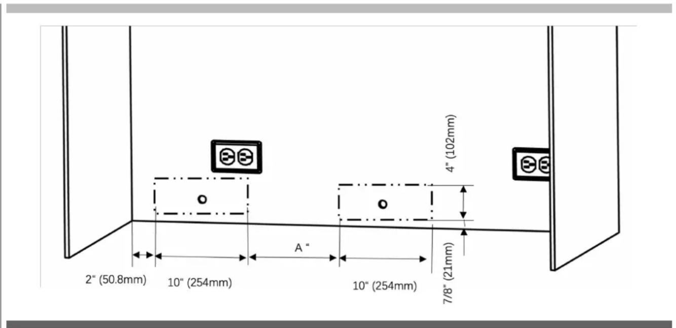
Location of the Electrical Wiring
Location of the electrical wiring must be within the range given below.

ATTENTION
Do not use extension cables or two-pin adaptors and do not remove the ground terminal of the grounding cable.

ATTENTION
A qualified electrician must ensure that the poles of the socket are connected correctly. Verify that the grounding of the socket is correct.
| Category | 30''+30''(76+76mm) | 30''+36''(76+91mm) | 36''+36''(91+91mm) |
| "A" Dimension | 19 1/8"(485mm) | 25 1/16"(637mm) | 25 1/16"(637mm) |
Location of the water system
The water connected to the water mains must be potable.
The location of the water system must be within the range given below.
The water system of the refrigerator must be connected to the water mains system in the house.
The user must be able to switch it on/off with the valve when necessary.
Objects that might pierce the water hoses or cause them to twist must not be present where the water line is installed.
Pressure of the water system must be between 25-80 psi (1.7-5.5 Bar).
If the water pressure exceeds 80 psi, install a pressure limiting device or water impact protector to the inlet valve.
Never install the product or operate the appliance if it is possible for the water pressure to exceed 120 psi.

WARNING
Make sure that there is no water leakage when making the water connections.
Otherwise, there will be water on the floor and the furniture will get damaged.
You will need a hose with a minimum length of 60^ (1.5 meters) and a diameter of "for water connections of the product during installation.
A connector that has a thread with an external diameter of must be used to connect the hose end to the product. Before completing the installation, make sure that water flows and there is no water leakage.
| Category 76+76 76+91 91+91 | |||
| "A" Dimension | 20" (508mm) | 20" (508mm) | 26" (60mm) |
Mounting Part list
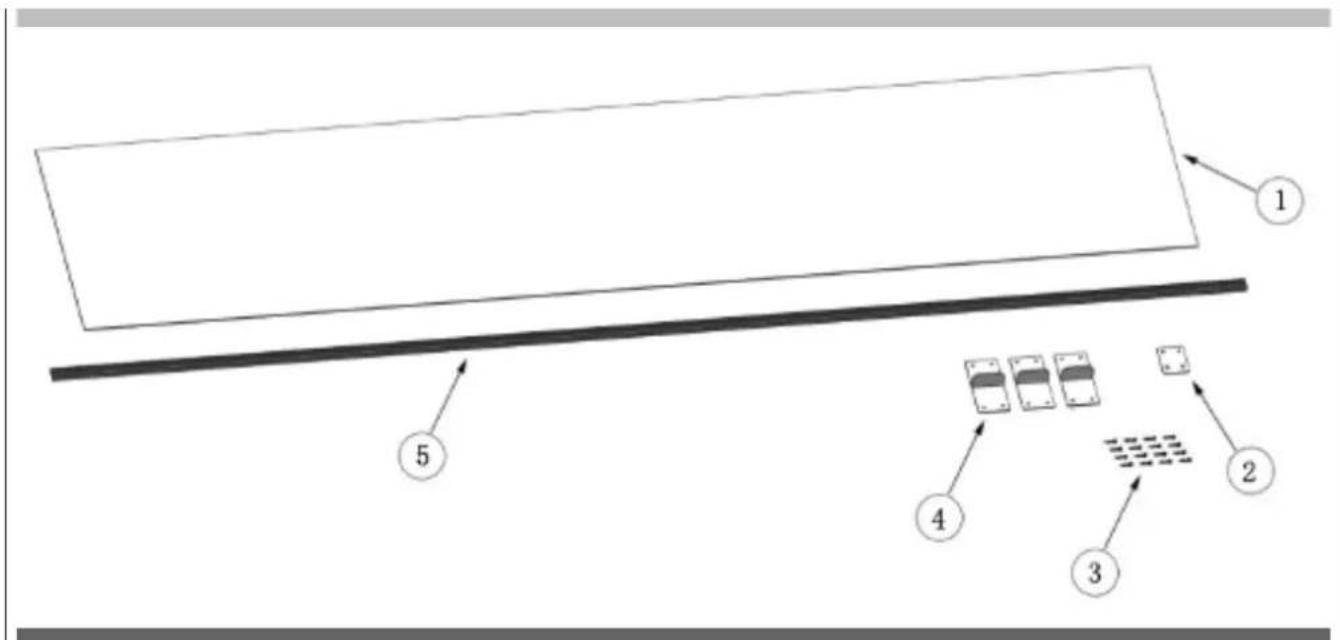
| No Part name spec Q'ty Remark | ||||
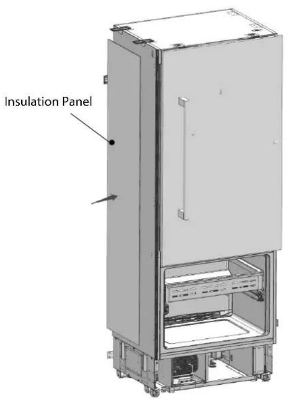
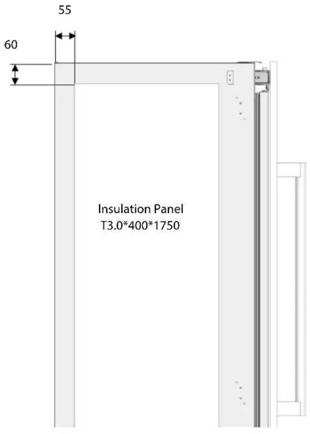
| 1 Insulation foam panel Sponge, gray, T3.0*400*1 | 750 1 | |||
| 2 Connecting bracket T2.0, Cr+zn-coating 2 | ||||
| 3 Truss washer head M4*12 16 | ||||
| 4 Fastener | POM | 3 | ||
| 5 Central cover | PVC extrusion L=1876 | 1 | ||

Stick the insulation panel (Item No1) to the side of one appliance so that it remains in between two cabins.
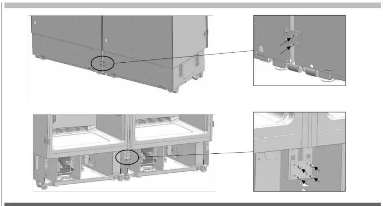
Attaching the fasteners and connecting bracket
Screw the connecting bracket(Item No2) and fasteners (Item No4) that are going to connect two refrigerators together.
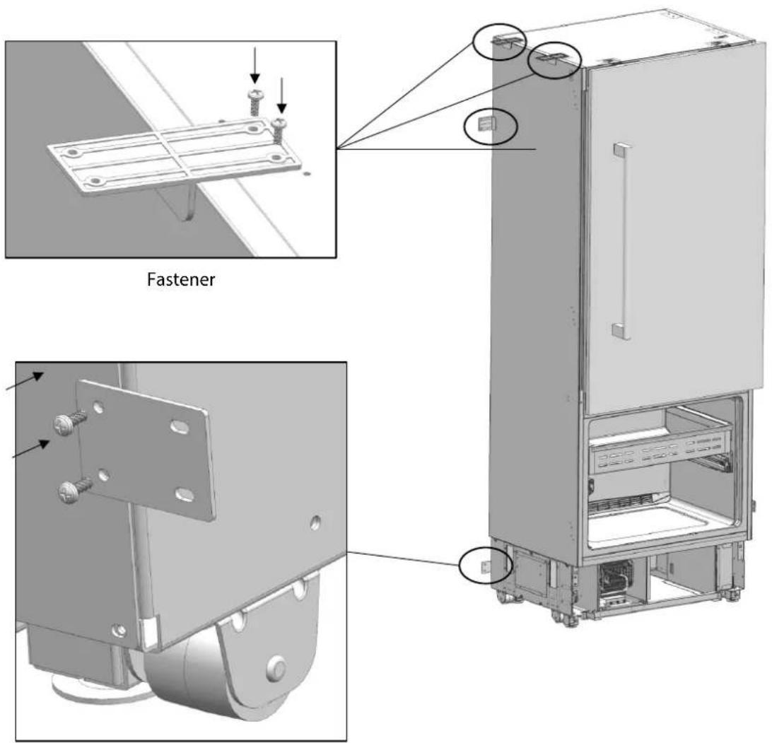
Connecting bracket
Make power and water connections of the refrigerator as explained earlier in this manual.
After making sure that they are in alignment Screw the upper brackets to the other refrigerator.
After making sure that they are in alignment screw the lower brackets to the other refrigerator.
Adjusting the height of the refrigerator in the cabinet
Adjust the refrigerator height using the adjustable feet.


WARNING
Fist start with raising the front feet (before the back feet) to reduce the risk of the appliance falling frontward.
A/D-Turn the key clockwise to lift the front.
B/C -Turn the key clockwise to lift the rear.
Screwing the bracket furniture on the cabinet side walls
Secure the appliance connecting brackets to the cabinet with 12 screws.

Screwing the bracket furniture on the cabinet top wall
Secure the appliance connecting brackets to the cabinet with 4screws.

Attaching the decorative trim parts
Attach the side trim onto the cabinet-appliance connecting brackets.
Attach the top trim onto the cabinet-appliance connecting brackets.
Attach the trim furniture middle ( Item No5) between two refrigerators.
Completion installation
You can see previous pages for other installation procedures.
EN
TABLE DES MATIÈRES PAGE
12 - Double installation 50
Dimensions de I'armoire 50
Icane Mode Description

FM4BM30(I)FBI-FM4FBM36(I)FBI

FM4BM30(I)FBI-FM4FBM36(I)FBI