F7SRC24S1-L - Fridge Fulgor Milano - Free user manual and instructions
Find the device manual for free F7SRC24S1-L Fulgor Milano in PDF.

User questions about F7SRC24S1-L Fulgor Milano
0 question about this device. Answer the ones you know or ask your own.
Ask a new question about this device
Download the instructions for your Fridge in PDF format for free! Find your manual F7SRC24S1-L - Fulgor Milano and take your electronic device back in hand. On this page are published all the documents necessary for the use of your device. F7SRC24S1-L by Fulgor Milano.
USER MANUAL F7SRC24S1-L Fulgor Milano
natural_image
Pure electrical circuit lines without any symbolsFULGOR
MILANO
REFRIGERATORS
F7IRC3601
F7SRC36S1
F7IRC3001
F7SRC30S1
F7IRC2401
F7SRC24S1
COMBI REFRIGERATORS
F7PBM36S2
F7IBM36S1
FREEZERS
F7IFC30O1
F7SFC30S1
F7IFC24O1
F7SFC24S1
F7IFC1801
F7SFC18S1
WINE CELLARS
F7IWC2401
F7SWC24S1
COMBI WINE CELLARS
F7PBW24S2
F7IBW24O2
EN
INSTALLATION GUIDE
FR
NOTICE D'INSTALLATION
ES
GUIA DE INSTALACIÓN
1 IMPORTANT INSTRUCTIONS 4
1.1 Important safety instructions.... 4
1.2 Child safety.... 4
2 TECHNICAL REQUIREMENTS 5
2.1 Appliance features and installation requirements.... 5
2.2 Installation cutout features: panel ready column.... 6
2.3 Installation cutout features: panel ready bottom-mount freezer.... 8
2.4 Installation cutout features: cladded column.... 10
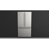
2.5 Installation cutout features: Stainless exterior Pro (European standard).... 12
2.6 Installation cutout features: Stainless exterior Pro (North American standard).... 14
3 PREPARING THE INSTALLATION 19
3.1 Transport to installation site and unpacking.... 19
3.2 Electrical and water connection.... 19
3.3 Energy: Alternatives and Home Automation 20
3.4 Leveling.... 21
4 CUTOUT DIMENSIONS 21
4.1 Cutout dimension for combined installation (for all models except top compressor units).... 21
5 PANELS MOUNTING 22
5.1 Overlay door panel layout.... 22
5.2 Overlay panels layout for appliance with one bottom-drawer 24
5.3 Overlay panels layout for appliance with glass door and one bottom drawer.... 25
5.4 Overlay panel for column 26
5.5 Overlay panels layout for column with glass door 27
5.6 Panel dimensions: single bottom drawer 28
5.7 Panel dimensions column models.... 29
5.8 Mounting panels to the door 30
5.9 Mounting panels to the drawer 30
6 INSTALLATION: BOTTOM COMPRESSOR MODELS 33
6.1 Built-in installation of single appliance 33
6.2 Built-in installation of two or more appliances 33
6.3 Maximum cabinet depth for panel ready appliance with single door panel 38
7 COMPLETING THE INSTALLATION 39
7.1 Anti-tipping safety assembly.... 39
7.2 Ventilation 40
7.3 Mounting the handles on cladded models.... 41
7.4 Post installation checklist.... 41
7.5 Start up.... 41
1.1 Important safety instructions
Symbols used in the Guide:

Note
Tips for the correct use of the appliance

Important
Directions to avoid appliance damage

Warning
Directions to prevent injury
1.2 Child safety
natural_image
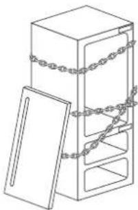
Line drawing of a cabinet with chains attached to the door (no text or symbols)DANGER: Risk of child entrapment. Before you dispose of your old refrigerator, freezer or wine cellar:
Remove the doors;
Cut the power cord of and dispose of separately;
Leave the shelves in place so that children may not easily climb inside.

Dimensions in parentheses are in inches.
Weights in parentheses are in pounds.
Temperatures in parentheses are in degrees Fahrenheit.
2.1 Appliance features and installation requirements
Weight with packaging 18" model up to 150 kg (331 lb)
24" model up to 170 kg (375 lb)
30" model up to 190 kg (419 lb)
36" model up to 200 kg (441 lb)
Voltage AC 110 - 120V 60Hz
| Power supply cable | 90° Nema 5-15P |
| Dedicated circuit breaker | 15A |
| Potable water supply pressure | from 0.05 MPa to 0.5 MPa (0.5 Bar - 5 Bar) |
| Water connection 3/4" NPT (1/4" elbow adapter included) | |
| Provided installation accessories | - Anti tipping kit- Lateral mounting brackets (10 pieces)- Overlay panel mounting kit (if applicable)- Water connection kit (if applicable)- 4 mm (1/8") allen / hex key |
| Additional equipment necessary | - Phillips head screwdriver- wood drill- 2.5 mm (1/8") bit for wood- 8 mm (3/8") bit for walls- 10 mm (3/8") bit for walls- 17 mm (11/16") wrench- 19 mm (3/4") wrench- 13 mm (1/2") socket to adjust the rear leveling legs- 2.5 mm hex key for installing handles |
| Other provided accessories | - Cleaning kit |
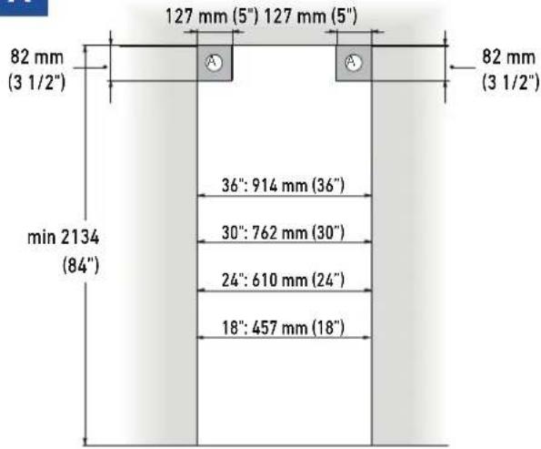
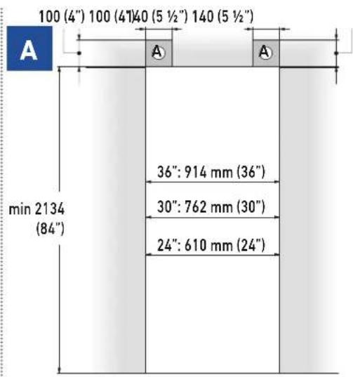
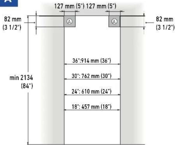
2.2 Installation cutout features: panel ready columns
A Minimum cutout height
2134 mm (84")
Cutout width
36" model: 914 mm (36")
30"model: 762 mm (30")
24" model: 610 mm (24")
18" model: 457 mm (18")
Minimum cutout depth
610 mm (24") + panel thickness for flush install
Area to be left clear for the anti-tipping brackets
127 mm (5") for both right and left sides
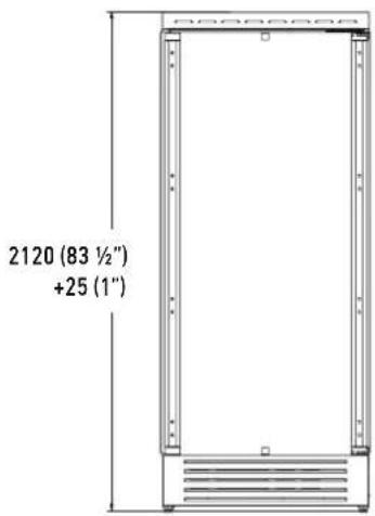
B Appliance height
2120 mm (83 1/2") + 25 mm (1")
A
text_image
82 mm (3 1/2") min 2134 (84") 127 mm (5") 127 mm (5") 82 mm (3 1/2") 36": 914 mm (36") 30": 762 mm (30") 24": 610 mm (24") 18": 457 mm (18)B
text_image
2120 (83 ½") +25 (1")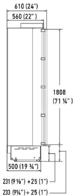
text_image
610 (24") 560 (22") 1808 (71 ¼") 500 (19 ¾") 231 (9 ½") + 25 (1") 233 (9¼") + 25 (1)Door Swing Clearance
36" model: 1489 mm (58 5/8")
30" model: 1338 mm (52 58 ")
24" model: 1187 mm (46 3/4")
18" model: 1036 mm (40 34 ")
text_image
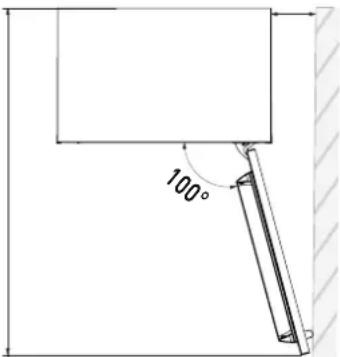
100°Minimum distance from the wall (hinge side)
36" model: 158 mm (6 ¼")
30" model: 132 mm (5 ¼")
24" model: 108 mm (4 ¼")
18" model: 82 mm (3 ¼")

90° hinges available to order as spare part.
text_image
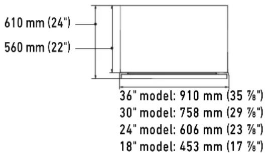
610 mm (24") 560 mm (22") 36" model: 910 mm (35 7/8") 30" model: 758 mm (29 7/8") 24" model: 606 mm (23 7/8") 18" model: 453 mm (17 7/8")2.3 Installation cutout features: panel ready with bottom-mount freezer
A Minimum cutout height
2134 mm (84")
Cutout width
36" model: 914 mm (36")
30" model: 762 mm (30")
24" model: 610 mm (24")
Minimum cutout depth
610 mm (24") + panel thickness for flush install
Area to be left clear for the anti-tipping brackets
127 mm (5") for both right and left sides
B Appliance height
2120 mm (83 1/2") + 25 mm (1")
text_image
100 (4") 100 (4")40 (5 ½") 140 (5 ½") A 36": 914 mm (36") 30": 762 mm (30") 24": 610 mm (24") min 2134 (84")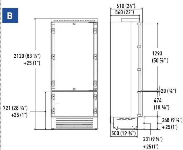
text_image
B 2120 (83 ½") +25 (1") 721 (28 ¾") +25 (1") 610 (24") 560 (22") 1293 (50 ¾") 20 (¾") 474 (18 ¾") 248 (9 ¾") +25 (1") 500 (19 ¾") 231 (9 ½") +25 (1)Door Swing Clearance
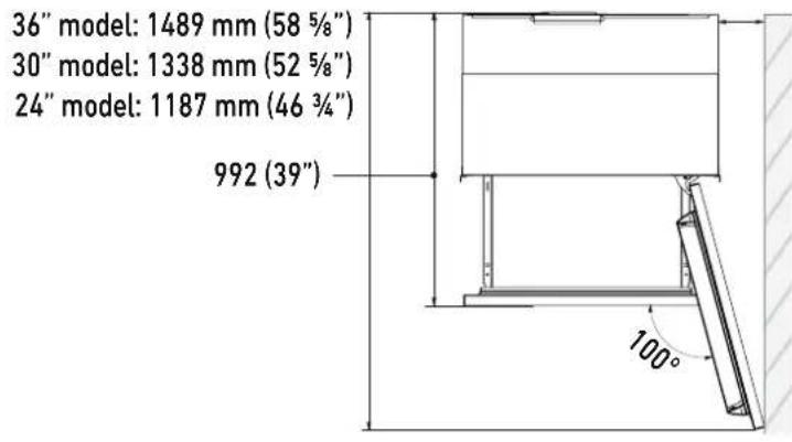
text_image
36" model: 1489 mm (58 5/8") 30" model: 1338 mm (52 5/8") 24" model: 1187 mm (46 3/4") 992 (39") 100°Minimum distance from the wall (hinge side)
36" model: 160 mm (6 ¼")
30" model: 125 mm (5")
24" model: 90 mm (3 ½")

90° hinges available to order as spare part
text_image
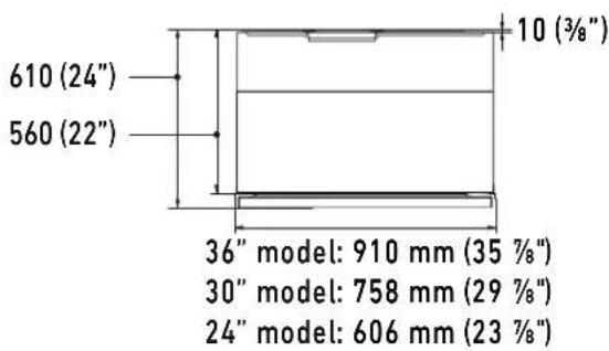
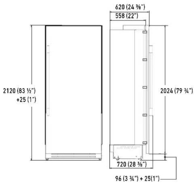
610 (24") 560 (22") 10 (3/8") 36" model: 910 mm (35 %8") 30" model: 758 mm (29 %8") 24" model: 606 mm (23 %8")2.4 Installation cutout features: cladded columns

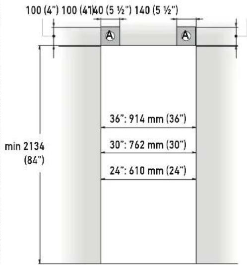
Minimum cutout height
2134 mm (84")
Cutout width
36" model: 914 mm (36")
30" model: 762 mm (30")
24" model: 610 mm (24")
18" model: 457 mm (18")
Minimum cutout depth (for flush install)
630 mm (24 3/4")
Area to be left clear for the anti-tipping brackets
127 mm (5") for both right and left sides

Appliance height
2120 mm (83 1/2") + 25 mm (1")
A
text_image
82 mm (3 1/2") min 2134 (84") 127 mm (5") 127 mm (5") A A 82 mm (3 1/2") 36":914 mm (36") 30": 762 mm (30") 24": 610 mm (24") 18": 457 mm (18)B
text_image
2120 (83 ½") +25 (1") 620 (24 ¾") 558 (22") 2024 (79 ¾") 720 (28 ¾") 96 (3 ¾") + 25(1")Door Swing Clearance
36" model: 1487 mm (58 ½")
30" model: 1336 mm (52 58 ")
24" model: 1185 mm (46 58 ")
18" model: 1034 mm (40 3/4")
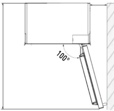
text_image
100°Minimum distance from the wall (hinge side)
36" model: 139 mm (5 ½")
30" model: 103 mm (4 18 ")
24" model: 89 mm (3 ½")
18" model: 63 mm (2 ½")

90° hinges available to order as spare part
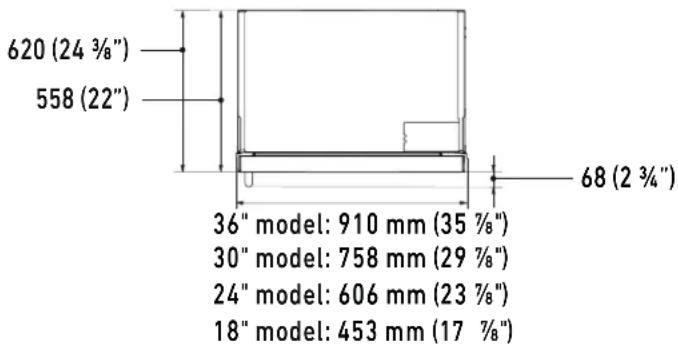
text_image
620 (24 3/8") 558 (22") 36" model: 910 mm (35 7/8") 30" model: 758 mm (29 7/8") 24" model: 606 mm (23 7/8") 18" model: 453 mm (17 7/8") 68 (2 3/4")2.5 Installation cutout features: Stainless exterior Pro
(North American standard cutout width)
A Minimum cutout height
2134 mm (84")
Minimum cutout width
36" model: 914 mm (36")
30" model: 762 mm (30")
24" model: 610 mm (24")
Depth with door
635 mm (25")
Area to be left clear for the anti-tipping brackets
127 mm (5") for both right and left sides
B Appliance height
2120 mm (83 1/2") + 25 mm (1")
A
text_image
100 (4") 100 (4")40 (5 ½") 140 (5 ½") min 2134 (84") 36": 914 mm (36") 30": 762 mm (30") 24": 610 mm (24)
When installing our top compressor models in a standard NA cut out it is recommended to use the J-profile trim kit to close the lateral gap of the appliance, alternatively use the standard plastic mounting clips when installing unit into Euro width cabinet. (Shown on next page) Installing in the unit in a standard North American "cutout" without the J-profile trim kit, will result in a larger gap along the cabinet opening.
B
text_image
2120 (83 ½") +25 (1") 613 (24 ½") +25 (1") 635 (25") 195 (7 ¾") 8 (¾") 1296 (50") 8 (¾") 516 (20 ¾") 97 (3 ¾") +25 (1") 560 (22") 693 (27 ¼)Door Swing Clearance
text_image
36" model: 1470 mm (57 7/8") 30" model: 1320 mm (52") 24" model: 1170 mm (46") 1016 mm (40") 36" model: 230 mm (9") 30" model: 195 mm (7 3/4") 24" model: 160 mm (6 1/4") 100°Minimum distance from the wall (hinge side)
text_image
635 mm (25") 560 mm (22") 75 mm (3") 10 mm (¾") 58 mm (2 ½") 36" model: 914 mm (36") 30" model: 762 mm (30") 24" model: 610 mm (24)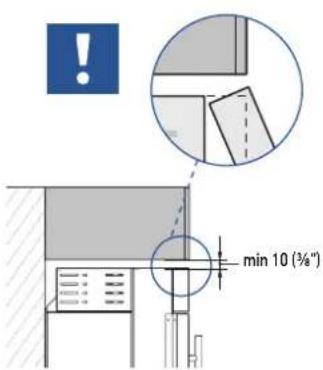
text_image
min 10 (¾°)
If the units are to be installed inside a cutout or within an enclosed structure, it is necessary to design a ventilation shaft at the back of the cutout to assure proper ventilation at the back of the unit.
Cross-sectional chimney ventilation area should equal 200cm ^4 (31in ^2 ).
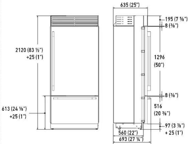
2.6 Installation cutout features: Stainless exterior Pro
(European standard cutout width)
A Minimum cutout height
2134 mm (84")
Minimum cutout width
36" model: 900 mm (35 1/2")
30" model: 750 mm (29 5/8")
24" model: 600 mm (23 3/4")
Depth with door
635 mm (25")
Area to be left clear for the anti-tipping brackets
127 mm (5") for both right and left sides
B Appliance height
2120 mm (83 1/2") + 25 mm (1")
A
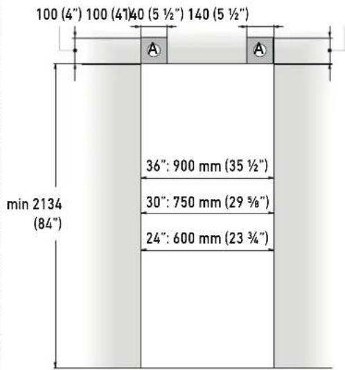
text_image
100 (4") 100 (4)40 (5 ½") 140 (5 ½") min 2134 (84") 36": 900 mm (35 ½") 30": 750 mm (29 ¾") 24": 600 mm (23 ¾)
When installing our top compressor models in a new construction, it is recommended to use the European "cutout" dimensions to achieve a minimal gap on the lateral sides and avoid the need to use the J-profile trim kit. Installing in the unit in a standard North American "cutout" without the J-profile trim kit, will result in a larger gap along the cabinet opening.
B
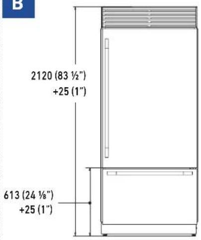
text_image
2120 (83 ½") +25 (1") 613 (24 ½") +25 (1)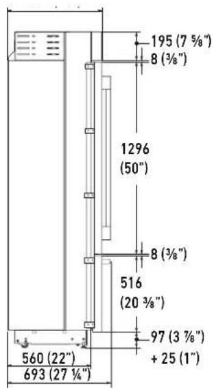
text_image
195 (7 ⅓") 8 (⅓") 1296 (50") 8 (⅓") 516 (20 ⅓") 97 (3 ⅓") + 25 (1") 560 (22") 693 (27 ⅓)Door Swing Clearance
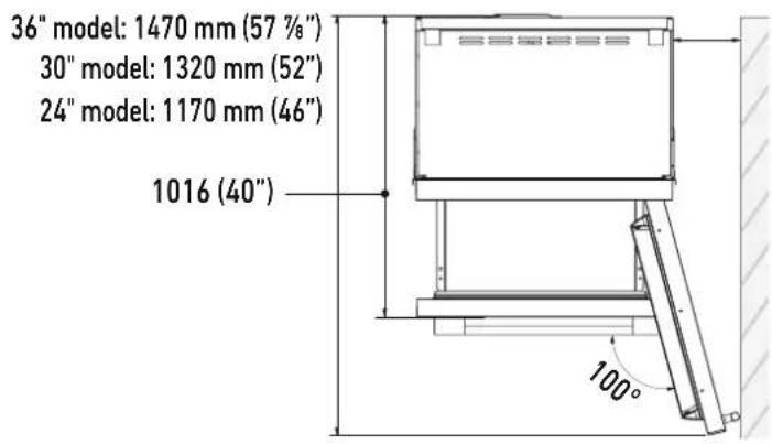
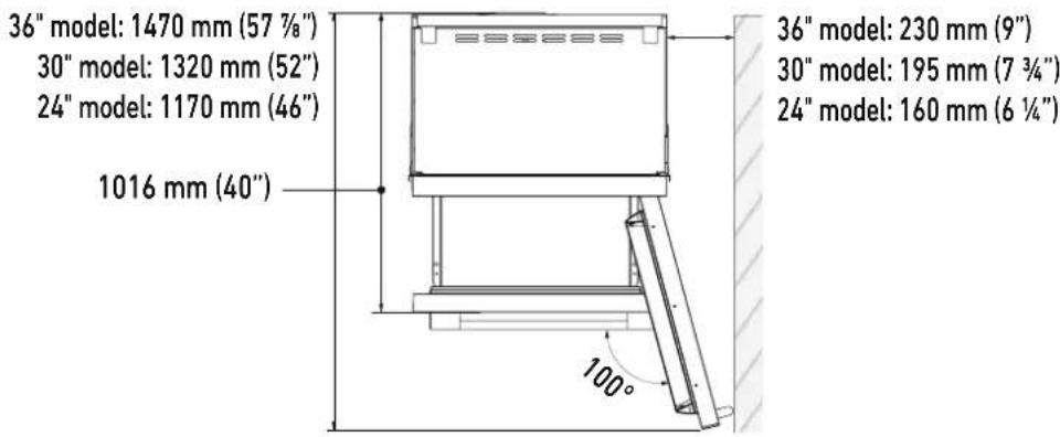
text_image
36" model: 1470 mm (57 %"") 30" model: 1320 mm (52") 24" model: 1170 mm (46") 1016 (40") 100°Minimum distance from the wall (hinge side)
36" model: 230 mm (9")
30" model: 195 mm (7 3/4")
24" model: 160 mm (6 ¼")
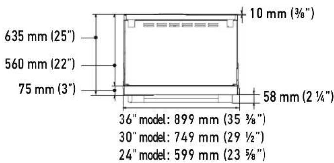
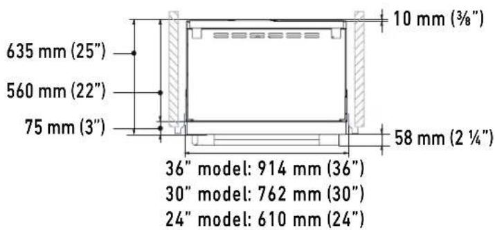
text_image
635 mm (25") 560 mm (22") 75 mm (3") 10 mm (¾") 58 mm (2 ½") 36" model: 899 mm (35 ¾") 30" model: 749 mm (29 ½") 24" model: 599 mm (23 ¾"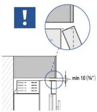
text_image
min 10 (%") !
If the units are to be installed inside a cutout or within an enclosed structure, it is necessary to design a ventilation shaft at the back of the cutout to assure proper ventilation at the back of the unit. Cross-sectional chimney ventilation area should equal 200cm^2 (31in ^2 ).
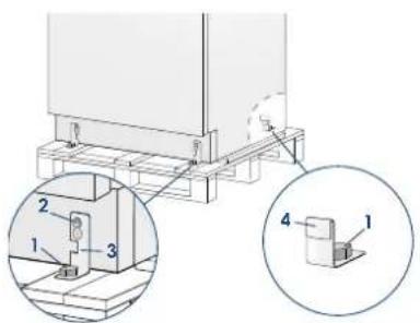
3.1 Transport to installation site and unpacking

The appliance is very heavy. Take maximum care during handling to avoid injury.

The appliance should always be transported in an erect position. Avoid at all costs leaning it on its front side.
text_image
Technical diagram showing a mechanical assembly with numbered components and an inset magnified view of a component detail.Since this is a large and heavy appliance, before transporting the appliance, check the access to the location where it will be installed (door size, maneuvering space in stairwells, etc.).
The appliance is attached to the base of the packaging (pallet) through four bolts which can be removed using a 19 mm (3/4") wrench.
It is recommended to use a manual transporting device to move the appliance to the installation site, and only at this point to remove the base of the packaging.
The appliance should always be transported in an erect position.
If this is not possible, transport the appliance laying on its rear side.
Once at the installation site, the appliance, which is equipped with four wheels, can be taken off the pallet and positioned in the installation area.
Operate as follows:
Take off the four bolts securing [1] the appliance to the pallet by means of a 19 mm (3/4") wrench or socket.
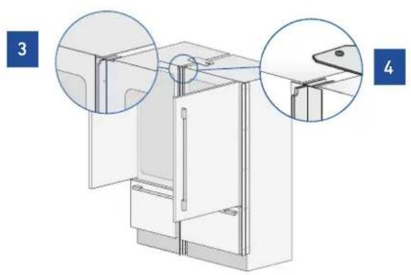
Remove the fixing brackets [3] and [4].
To release the front fixing bracket [3], loosen the rear wheel adjusting bolt [2] by means of a 13 mm (1/2") wrench or socket. Avoid straining this bolt at its stop points one way or the other so as to not damage
the rear leveling system.
Ensure the front leveling legs are retracted so that all 4 wheels are able to contact the floor for easiest maneuvering.
From the back or side of the unit and by means of a suitable, heavy duty hand trolley, take off the appliance and place it on the floor.
Be very careful to avoid any damage to floors. Delicate floors should be protected with plywood, hard cardboard or similar material panels.
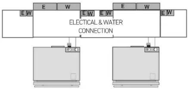
3.2 Electrical and water connection

The Built-in filter cannot make it safe to drink any water which is not already suitable for human consumption.

The appliance should be connected only to a potable water supply system.

Do not use extension cords or adapters. Once the appliance is fully installed, connected to the water supply (if applicable) and operational, in the event that the water supply must be turned off, (touch the button on control panel to disable the ice maker) before the main water is shut off to prevent the appliance from entering a 'NO WATER IN' alarm state.
• OVERHEAD VIEW •
flowchart
graph TD
    A["Device 1"] --> B["Switch"]
    C["Device 2"] --> D["Switch"]
    B --> E["Power Supply"]
    D --> F["Power Supply"]
    style A fill:#f9f,stroke:#333
    style C fill:#f9f,stroke:#333
    style B fill:#ccf,stroke:#333
    style D fill:#ccf,stroke:#333

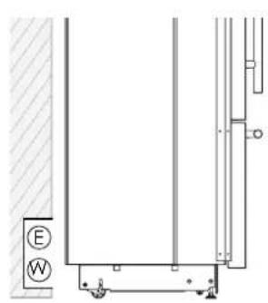
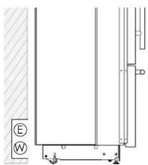
Electrical or water connections located directly behind the appliance must be recessed. Do not put the water shut-off valve directly behind the appliance. It should be in an accessible location.
The appliances are delivered from the factory for operation at 110V-120V AC - 60Hz (US and Canada).
They are provided with a suitable supply cable and plug to be connected to an appropriate 15A socket providing an effective grounding.
A dedicated 15A circuit breaker should also be installed and should be easily accessible so that it can be easily switched off before performing any installation or maintenance.
To connect to the water supply system (for appliances equipped with ice makers) a 1/4" waterline with accessible shut-off valve must be supplied.
The appliance is provided with a water adapter elbow which is suitable for the recommended water pressure and complies the applicable food and water regulations.
The water filter cartridge, which is provided with the appliance, should be installed according to the accompanying instructions. Please refer to water filter installation instructions contained in the water filter kit. The solenoid connection on the appliance is 3/4" diameter but is metric threaded (NPT). A standard garden hose threaded connector such as a braided stainless hose found at typical hardware stores will strip or damage the solenoid threads. It is recommended to use only the supplied 1/4" quick connect elbow adapter for connecting a 1/4" copper or polyethylene source water line to the appliance.

Do not use extension cords and/or multiple adapters for the power supply connection.
ELECTRICAL AND WATER SUPPLY BEHIND THE UNIT
BOTTOM COMPRESSORS
UNIT
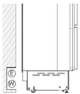
natural_image
Architectural or engineering diagram showing a vertical wall section with a horizontal floor and a small labeled component (E/W), no readable text or symbols present.TOP COMPRESSORS
UNIT
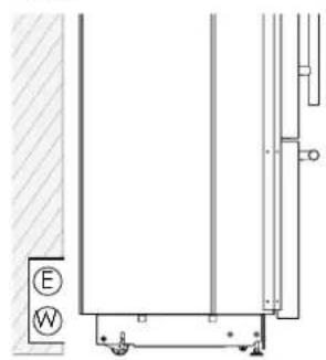
natural_image
Pure architectural or mechanical line drawing with no text, numbers, or symbols3.3 Energy: Alternatives and Home Automation
If energy is supplied through an alternative energy power source (solar, geothermal, etc.) or if home automation systems are installed with carrier signals in the power lines, it may be necessary to install an isolation transformer (not supplied) to prevent interference with the appliance's electronics.
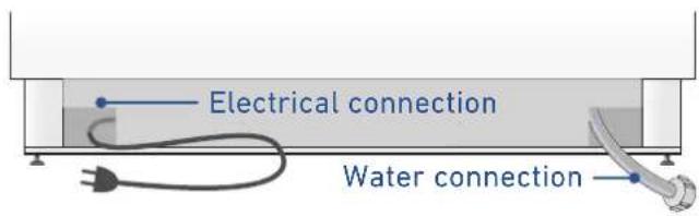
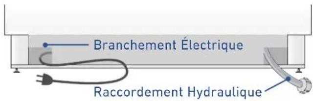
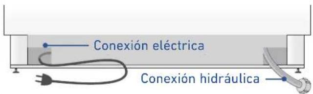
BOTTOM COMPRESSOR UNITS
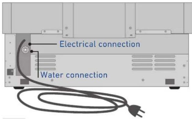
text_image
Electrical connection Water connectionfig.1 Back of appliance
Operate as follows:
Unwind the electric cable and connect it directly to the wall socket.
Make sure the appliance is in the Stand-by condition and that all lights are off; should it be not so press the Unit button do switch it off.
Connect the water cable behind the appliance [1].
natural_image
Diagram of a mechanical component with threaded fitting and connecting rod (no text or symbols)TOP COMPRESSORS UNIT:
text_image
Electrical connection Water connectionfig.2 Back of appliance
Operate as follows:
Unwind the electric cable and connect it directly to the wall socket.
Make sure the appliance is in the Stand-by condition and that all lights are off; should it be not so press the Unit button to switch it off.
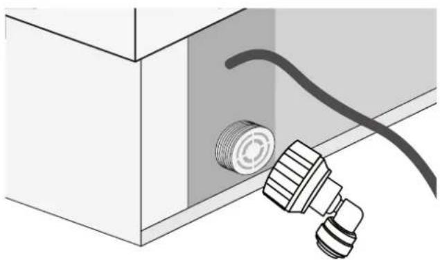
text_image
Diagram showing a device with labeled parts and a magnified inset illustrating fluid flow or mechanical components.fig.3 Front of appliance
Firmly tighten with fingers - a tool / wrench should not be needed to make a proper seal. Turn on the water and ensure all connections are not leaking prior to pushing the unit into the opening.
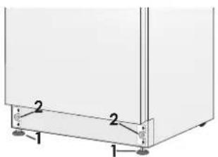
3.4 Leveling
Adjust the appliance level by means of the front levelling feet and the rear adjustable wheels.
text_image
2 2 1 1Operate as follows:
If necessary, remove the bottom plinth or grille (it is kept in position by magnets), adjust the height of the levelling feet [1] by means of a 17 mm (11/16") wrench.
Then adjust the height of the rear wheels by turning the front adjusting bolts [2] clockwise (raise) or counter-clockwise (lower) as it may be required.
Take care if using a power driver for this and lower the clutch to prevent damaging the leveling mechanism.
Remount the bottom plinth or grille.
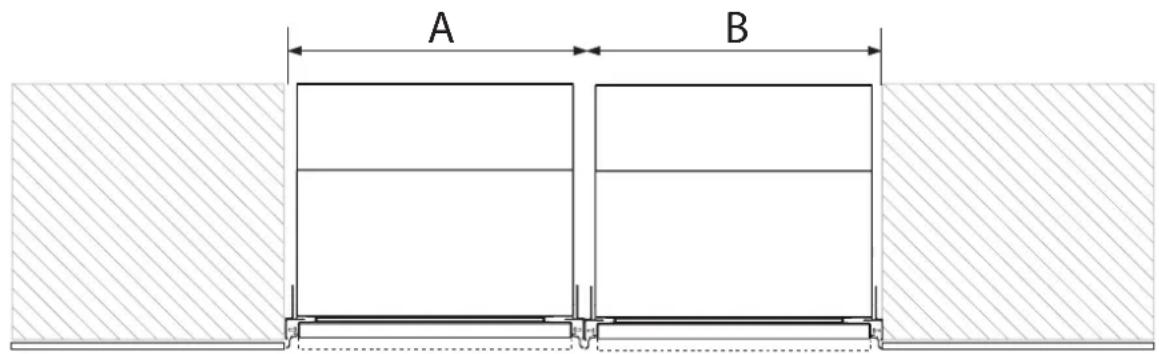
4.1 Cutout dimension for combined installation (for all models except top compressor units fitted to European-sized cutouts)
text_image
A BCORRECT SPACING BETWEEN APPLIANCES SHOWN LATER IN THIS MANUAL.
| A | |||||
| B | 18" model 24" | model 30" model 36" | model | ||
| 18" model 36"(914mm) 42"(1067mm) 48"(1220mm) 54"(1372mm) | |||||
| 24" model 42"(1067mm) 48"(1220mm) 54"(1372mm) 60"(1520mm) | |||||
| 30" model 48"(1220mm) 54"(1372mm) 60"(1520mm) 66"(1676mm) | |||||
| 36" model 54"(1372mm) 60"(1524mm) 66"(1676mm) 72"(1829mm) | |||||
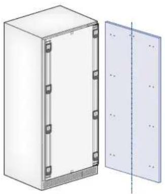
5.1 Overlay door panel layout
The dimensions of the panels are indicated in the table and drawings on subsequent pages.
Nevertheless, according to the requirements for aligning with other kitchen structures, the door panel can be higher than the upper edge of the refrigerator door.
The panels must be mounted using special brackets which attach to adjustable devices provided on the door and drawer and with brackets that anchor and adjust the panel's vertical direction.
Brackets and fixing screws are provided with the appliance and must be applied to the panel as indicated.

For shaker or framed panel styles, it may not be possible to affix the upper or lower leveling brackets unless the cabinet maker has accommodated their mounting with additional material on the back of the panel.
Operate as follows:
To prepare the panels to be mounted on the appliance, follow these steps, working on the back of the panel.
Door Panel
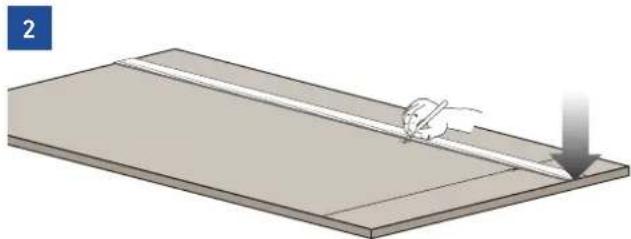
Draw a vertical center line on the panel from top to bottom [1].

natural_image
Simple 3D illustration of a small animal on a flat surface, no text or symbols presentStarting from the bottom edge of the panel, mark the positioning of the brackets [2].
natural_image
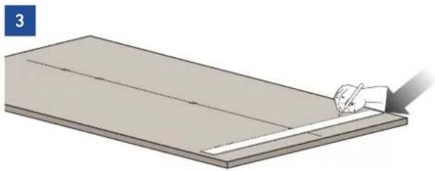
Diagram showing a hand using a tool to cut a flat surface with a downward arrow (no text or symbols)Following the corresponding table, mark the external and then the internal hole [3].
natural_image
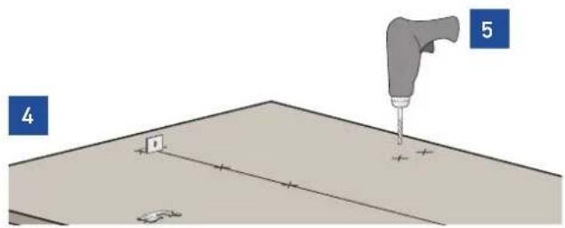
Illustration of a hand using a tool to cut or mark a flat surface, no text or symbols presentPosition the brackets on each set of marks to make sure they are aligned [4], if you choose to drill small pilot holes for the screws pay special attention to not pass through the panel entirely. [5].
text_image
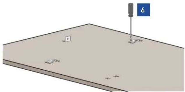
4 5Screw the brackets in place [6].
natural_image
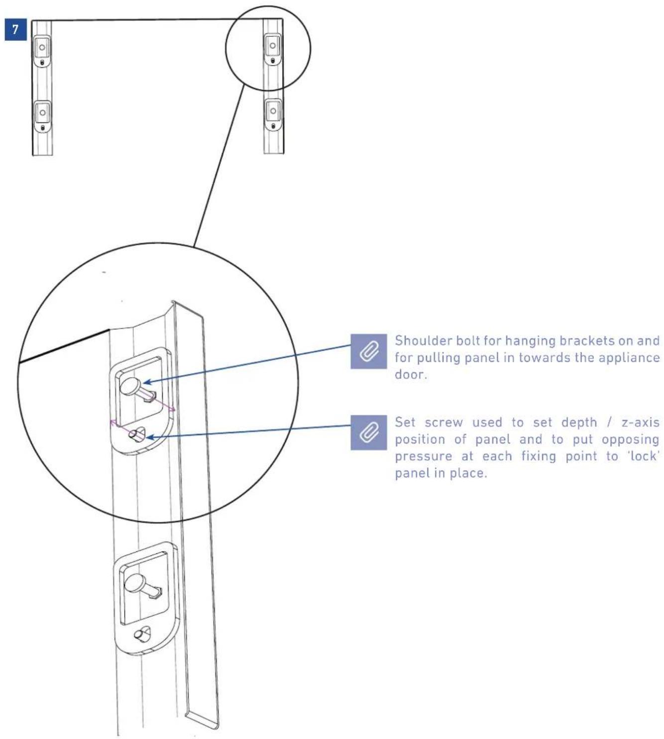
3D diagram of a mechanical assembly with a screwdriver and labeled components (no text or symbols)Prepare the appliance door for panel mounting by threading the shoulder bolts into the recessed receivers and the set screws into the other hole [7]. Ensure the end with the hex key socket is threaded into the door and not on the visible end. Thread this in far enough that it is flush with appliance door face so as not to interfere with hanging the panel. You will adjust these later.
text_image
7 Shoulder bolt for hanging brackets on and for pulling panel in towards the appliance door. Set screw used to set depth / z-axis position of panel and to put opposing pressure at each fixing point to 'lock' panel in place.5.2 Overlay panels layout for appliance with one bottom-drawer
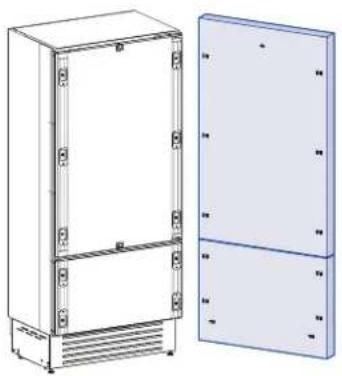
natural_image
Technical line drawing of a two-tiered electrical cabinet with side panels (no text or symbols)| 36" model 30" | model 24" model | ||
| A 9 | 08 (35 3/4") 756 (29 | 3/4) 604 (23-3/4") | |
| B 4 | 17 (16 3/8") 342 (13 | 1/2") 276.5 (10 7/8") | |
| C 3 | 54.5 (14") 279.5 (11") | 203.5 (8") | |
| D 3 | 68 (14 1/4") 302 (11 | 7/8") 235 (9 1/4") |

Dimension 'D' represents the safe zone for shaker / framed style panels to assure the mounting brackets can be affixed to an area of the panel with sufficient material to accept the screws.
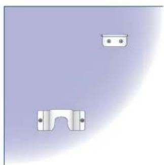
Holes positions:
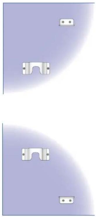
natural_image
Two identical abstract geometric shapes with white rectangular cutouts on a purple gradient background, no text or symbols present.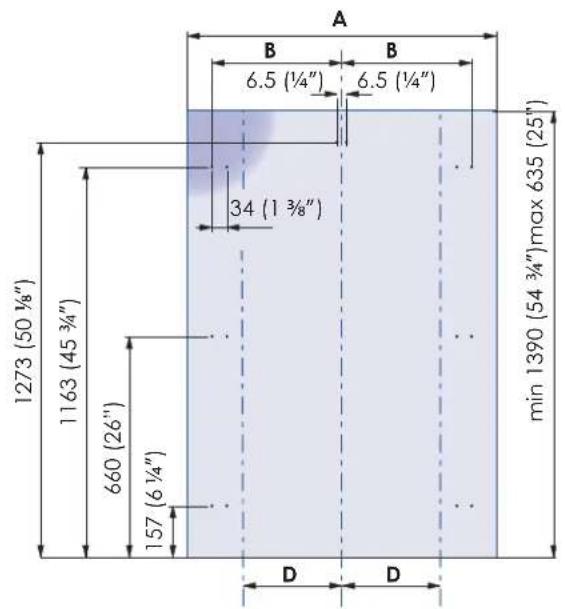
text_image
A B B 6.5 (¼") 6.5 (¼") 34 (1¾") min 1390 (54¾") max 635 (25") 1273 (50½") 1163 (45¾") 660 (26") 157 (6½") D D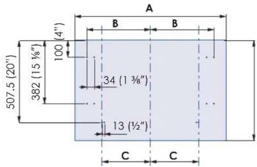
text_image
A B B (4") 100 382 (15 ½") 34 (1 ¾") 13 (½") C C 507.5 (20")5.3 Overlay panels layout for appliance with glass door and one bottom-drawer
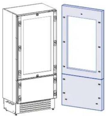
natural_image
Technical line drawing of a two-tiered stainless steel cabinet with front and side views (no text or symbols)| 24" model | |
| A 604 (23-3/4") | |
| B 276.5 (10 7/8") | |
| C 203.5 (8") | |
| D 235 (9 1/4") | |

Dimension 'D' represents the safe zone for shaker / framed style panels to assure the mounting brackets can be affixed to an area of the panel with sufficient material to accept the screws.
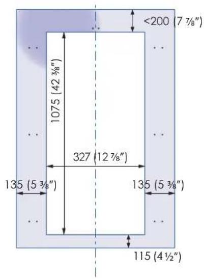
Holes positions: Door window dimens
text_image
1075 (42 3/8") 327 (12 7/8") 135 (5 3/8") 115 (4 1/2") <200 (7 7/8")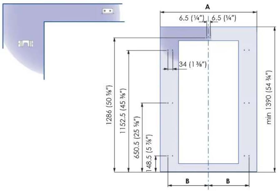
text_image
A 6.5 (1/4") 6.5 (1/4") 34 (1 3/8") min 1390 (54 3/4") 1286 (50 5/8") 1152.5 (45 3/8") 650.5 (25 5/8") 148.5 (5 7/8") B B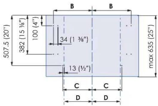
text_image
507.5 (20") 382 (15 ½") 100 (4") 34 (1 ¾") 13 (½") max 635 (25") B B C C D D5.4 Overlay panel for column
natural_image
Illustration of a white rectangular cabinet with side panels, showing internal components and mounting brackets (no text or symbols)| 36" model 30" | model 24" model 18" | model | ||
| A 9 | 08 (35 3/4") 756 (29 | 3/4") 604 (23 3/4") 4 | 51 (17 3/4") | |
| B 4 | 18 (16 1/2") 343 (13 | 1/2") 275 (10 7/8") 2 | 00 (7 7/8") | |
| D 3 | 68 (14 1/4") 302 (11 | 7/8") 235 (9 1/4") 15 | 8 (6 1/4") |

Dimension 'D' represents the safe zone for shaker / framed style panels to assure the mounting brackets can be affixed to an area of the panel with sufficient material to accept the screws.
natural_image
Pure electrical circuit lines without any symbolsHoles positions:
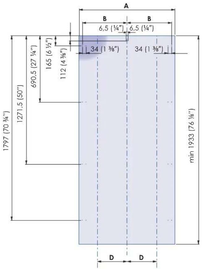
text_image
A B B 6,5 (¼") 6,5 (¼") 112 (4¾") 34 (1¾") 34 (1¾") min 1933 (76¾") 1797 (70¾") 1271.5 (50") 690.5 (27½") 165 (6½") 1125.5 Overlay panels layout for column with glass door
natural_image
Technical illustration of a rectangular enclosure with internal frame and side panel, showing mounting hardware (no text or symbols)| 24" model | |
| A 6 | 04 (23 3/4") |
| B 2 | 75 (10 7/8") |
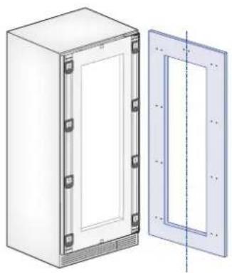
Door window dimensions: Holes positions:
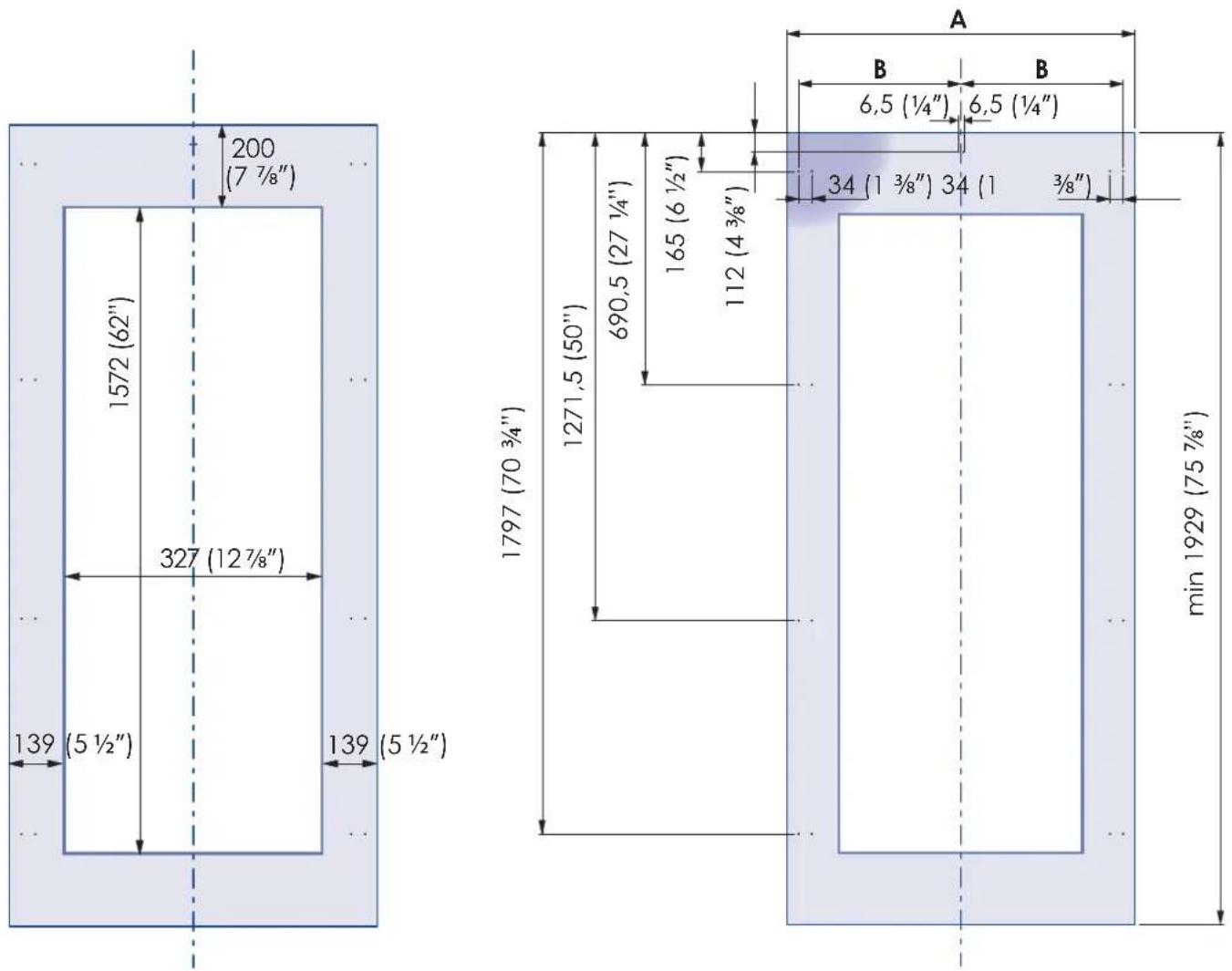
text_image
200 (7 7/8") 1572 (62") 327 (12 7/8") 139 (5 1/2") 139 (5 1/2") A B 6,5 (1/4") 6,5 (1/4") 1797 (70 3/4") 1271,5 (50") 690,5 (27 1/4") 165 (6 1/2") 112 (4 3/8") 34 (1 3/8") 34 (1 3/8") min 1929 (75 7/8)5.6 Panels dimensions: single bottom-drawer
Panels can have thickness ranging between 18 mm (3/4") and 28 mm (1-1/8").
Door panels can have a maximum weight 23 kg (51 lbs) and drawer panels may be a maximum weight of 11 kg (25 lbs). Exceeding these weights could void your warranty for any service issues which can be attributed to overweight panels.
The hinging mechanism on Fulgor Milano appliances is considered to be `Zero-clearance`. The door and drawer widths specified below assume the minimum cutout width is being used and a 3.5mm (1/8") reveal is desired around the panels. Adjust your panel dimensions accordingly to your own design criteria considering your cutout width and your reveal. Minimum reveal / gap should not be less than 1.5mm (1/16").
| MODEL | DOOR/DRAWER WIDTH A DOOR CUTOUT WIDTH B |
| 36" 908 | (35 3/4") 627 (24 3/4") |
| 30" 756 | (29 3/4") 477 (18 3/4") |
| 24" 604 | (23 3/4") 327 (12 7/8") |
text_image
2121 (83 ½") + 25 (1") 1390 (54 ¾") 3 (½") min 540 (21 ½") max 635 (25") max 635 (25")Example:
84" cutout height
36" cutout width
4" toe kick height
1/8" gap desired all around

natural_image
Two gray rectangular blocks with a dimension label 'A' at the bottom (no text or symbols within the blocks)
text_image
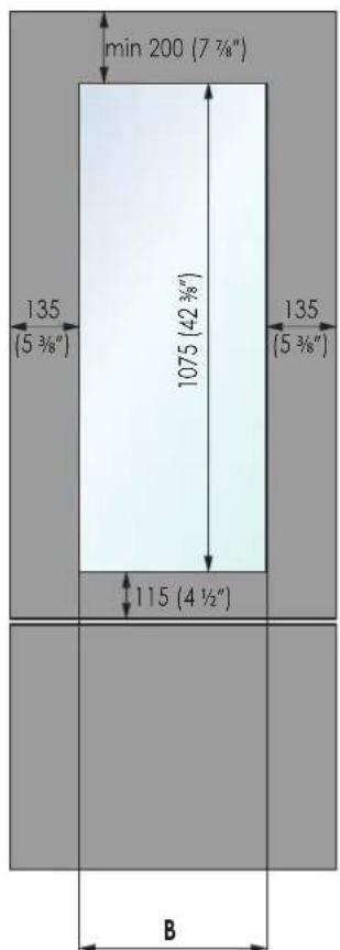
min 200 (7 ¾") 135 (5 ¾") 1075 (42 ¾") 135 (5 ¾") 115 (4 ½") BDoor panel:
Width: 35-3/4"
Height: 54-3/4"
Drawer panel:
Width: 35-3/4"
Height: 84"-1/8"-54-3/4"-1/8"-4" = 25"
If you want a 6" toe kick height then your bottom drawer panel
height would be 23"
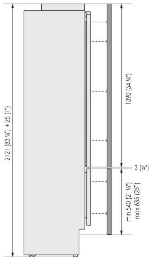
5.7 Panel dimensions column models
Panels with width ranging between 19 mm (3/4") and 28 mm (1 1/8").
Door panels with weight max of 34 kg (75 lb)
Exceeding these weights could void your warranty for any service issues which can be attributed to overweight panels.
The hinging mechanism on Fulgor Milano appliances is considered to be 'Zero-clearance'. The door and drawer widths specified below assume the minimum cutout width is being used and a 3.5mm (1/8") reveal is desired around the panels. Adjust your panel dimensions accordingly to your own design criteria considering your cutout width and your reveal. Minimum reveal / gap should not be less than 1.5mm (1/16").
| MODEL | DOOR WIDTH A DOOR GLASS WINDOW WIDTH B | |
| 36" 908 | (35 3/4") - | |
| 30" 756 | (29 3/4") - | |
| 24" 604 | (23 3/4") 327 (12 7/8") |
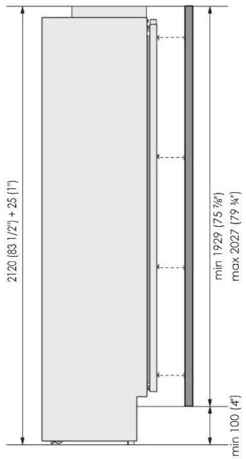
text_image
2120 [83 1/2"] + 25 (1") min 1929 (75 7/8") max 2027 (79 3/4") min 100 (4")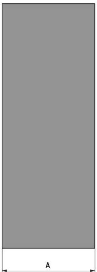
natural_image
Solid gray rectangle with a labeled dimension 'A' at the bottom (no other text or symbols)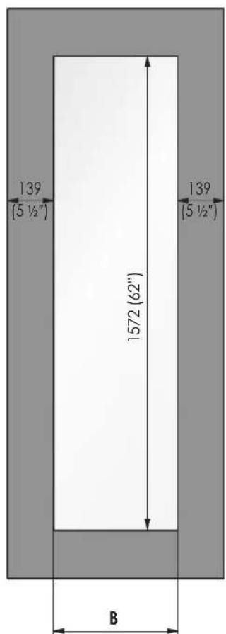
text_image
139 (5 ½") 1572 (62") 139 (5 ½") BFor fridge and freezer columns For wine columns
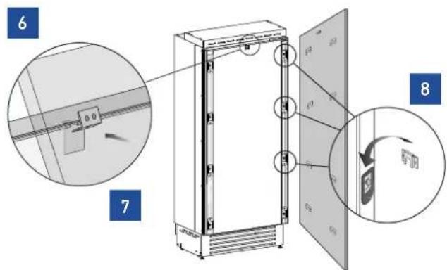
5.8 Mounting panels to the door

Once all mounting and alignment brackets have been applied to the panels, you can begin installing the door.
Hook the panel to the fixing devices starting from the top aligning brackets [6].
At this point, alignment between the panel and adjacent cabinets can be adjusted using the alignment brackets [7] and mounting brackets [8].
text_image
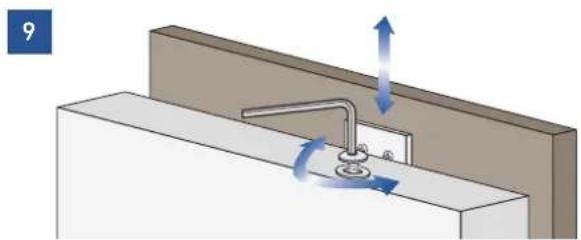
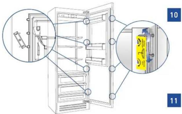
Technical diagram of an refrigerator with labeled components and a magnified inset showing internal structure and rotation.Vertical alignment: tighten or loosen the screw in the brackets to raise or lower the panel [9].
natural_image
Diagram of a faucet assembly with directional arrows indicating flow or movement (no text or symbols)Depth alignment: working from the inside of the door, after lifting up the magnetic seal on the handle side and rotating the plastic covers on the hinge side, adjust the panel position in the Z-direction by adjusting the shoulder bolts and setscrews with the 4mm hex key in conjunction with each other finally locking each mounting position in place [10 & 11].
text_image
Technical diagram of a refrigerator with labeled parts and close-ups showing internal components and assembly details
Once the front panel has been adjusted, check that the gasket has been repositioned correctly to assure the door/drawer are closing and sealing correctly to avoid operational errors of the unit.
For models accepting custom overlay panels no handles are included with the product. You are free to supply and mount your own handles matching your kitchen's aesthetic or order a Fulgor Milano handle accessory kit from the dealer. Follow the handle mounting instructions that are included with the handles. You may need to countersink screw heads when attaching handles.
5.9 Mounting panels to the drawer

Once all brackets and handles have been applied to the panels, you can begin installing the bottom drawer.
Operate as follows:
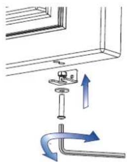
Partially tighten the screw to the nut in the appliance drawer [1].

natural_image
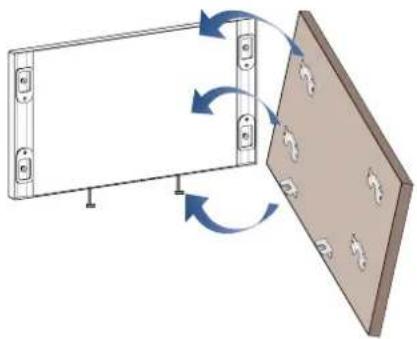
Diagram showing a mechanical assembly with arrows indicating direction of motion (no text or symbols)Hook the bottom drawer panel starting from the adjustment bolts on the bottom [2].
2
natural_image
Diagram showing a device with two panels, one with a switch and the other with a grid pattern, connected by directional arrows indicating rotation or assembly (no text or symbols present)It is now possible to align panels to adjacent cabinets in height using the lower alignment bolts and brackets, [3] tightening or untightening the screws into position as needed. With the screw slightly tightened, move the panel sideways manually to align it to the other panels on the unit or other adjacent structures.
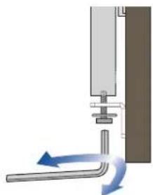
Set the bottom adjustment bolts using the lock nut against the bottom of the drawer once you are satisfied with the height alignment.
3
natural_image
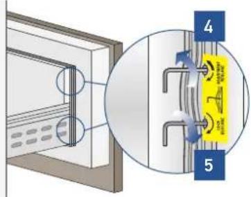
Pure diagram of a mechanical or fluidic device with directional arrows indicating flow or movement (no text or symbols)Depth alignment: working from the inside of the drawer, after lifting up the magnetic seal or rotating the cover plate where necessary, adjust the panel position in the Z-direction by adjusting the shoulder bolts and setscrews with the 4mm hex key in conjunction with each other finally locking each mounting position in place [4 & 5].
text_image
Diagram showing a mounted device with labeled parts and a magnified view of a yellow component with blue arrows indicating flow or movement.IMPORTANT: The following instruction for installation apply to all Fulgor Milano models.
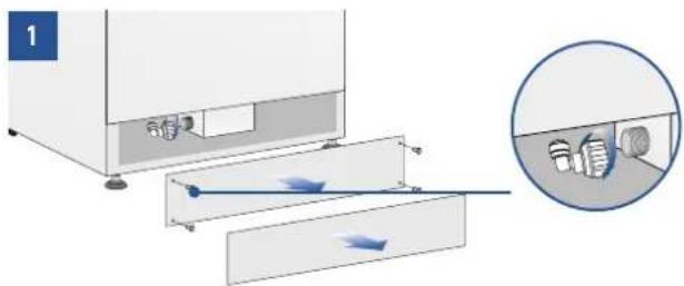
6.1 Built-in installation of single appliance
For a built-in installation, to cover gaps between the appliance and the adjacent cabinets and affix the appliance to the cabinetry, use the supplied 10 x piece bracket kit. Follow the instructions included in the bag with the brackets for placement of brackets on the appliance.
Operate as follows:
Push the appliance into the installation cutout [1].
1
natural_image
Pure architectural line drawing of a cabinet or enclosure structure without any text, numbers, or symbolsAlways mount front panel on door before pushing the unit into its final position inside the cutout or structure.
Check the levelling of the appliance, adjusting its feet and wheels to correct it.
Secure the appliance to the adjacent cabinets using the 10 x spacer brackets. [2].
Door must be open to access the brackets. Screws for fixing the brackets to adjacent cabinetry are not included.
2
natural_image
Technical line drawing of a door with two inset views showing internal components (no text or symbols)Mount the bracket covers: first insert them laterally and then push firmly until a "click" is heard [3].
3
natural_image
Technical line drawing of a door assembly with an inset showing internal components (no text or symbols)Side profiles mounting:
(Bird's eye view)
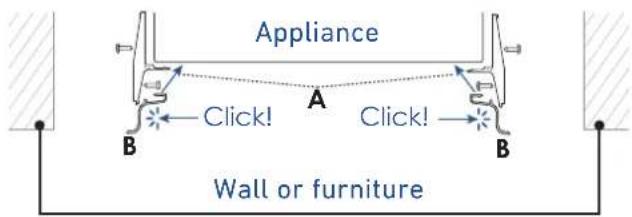
text_image
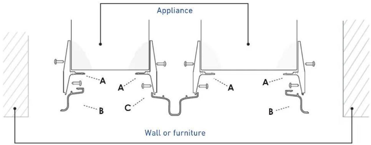
Appliance Click! A Click! B B Wall or furnitureA Plastic connecting brackets
B Profile trim cover
6.2 Built-in installation of two or more appliances
The central profile is provide with freezer and wine cellar columns.

Plastic covering frames are provided for closing gaps between the appliance and the adjacent cabinets.
Operate as follows:
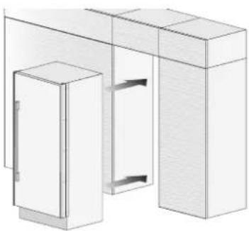
Position the appliances in front of the installation area, leaving enough space to operate at their back [1].
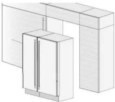
natural_image
Architectural line drawing of a cabinet and adjacent wall panels (no text or symbols)IMPORTANT: the appliances must be level with one another. This can most easily be achieved by aligning the holes in the mounting brackets on each appliance with one another.
Access the back of the appliances to mount the joining brackets: fix one side of the top and lower brackets to one of the appliances and subsequently to the other [1] minding the gap as per the table on the subsequent pages.
BOTTOM COMPRESSOR UNITS
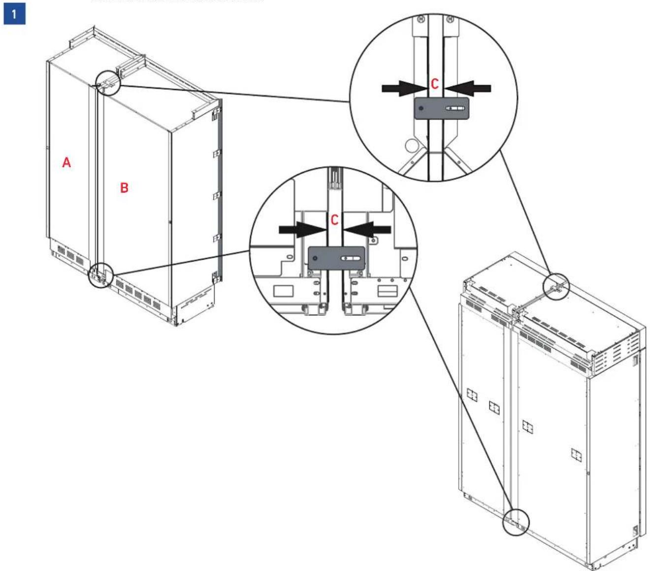
text_image
1 A B C CTOP COMPRESSOR UNITS
Do the same at the front lower section of each appliance with the provided bracket [2].
2
BOTTOM COMPRESSOR UNITS
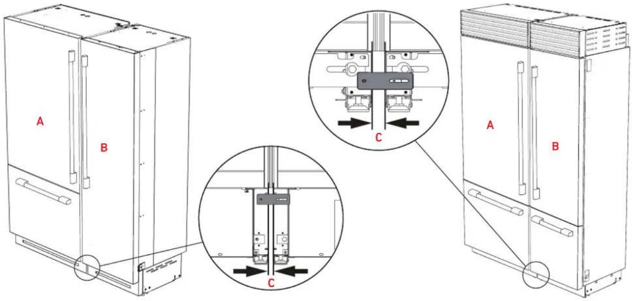
text_image
A B C A B CTOP COMPRESSOR UNITS
| Distance between units (A+B) | |||||
| C | A | ||||
| 18" model 24" | model 30" model 36" | model | |||
| B | 18" model 7/8" (22 mm) 15/16" (23.5 mm) 1" (24.5 mm) 1" (25.5 mm) | ||||
| 24" model 15/16" (23.5 mm) 1" (25 mm) 1" (26 mm) 1 | 1/16" (27 mm) | ||||
| 30" model 1" (24.5 mm) 1" (26 mm) 1 1/16" (27 mm) 1 | 1/8" (28 mm) | ||||
| 36" model 1" (25.5 mm) 1 1/16" (27 mm) 1 1/8" (28 mm) 1 1/8" (29 mm) | |||||
Once the appliances have been adjusted and properly levelled, loosen the two screws holding the sealing plate in position.
Lower the plate until flush with the floor, and re-tighten the screws. This will ensure optimized airflow through the condenser necessary for proper operation.
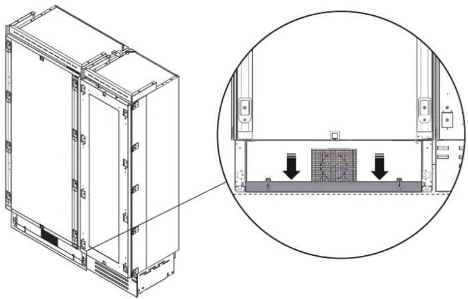
natural_image
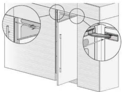
Technical line drawing of a server rack unit with an inset close-up showing internal components and mounting features (no text or symbols)Next join them at the front attaching the plastic connecting brackets with the supplied screws [3]. It is suggested to use two screws for connecting each bracket; one from each side [4].
natural_image
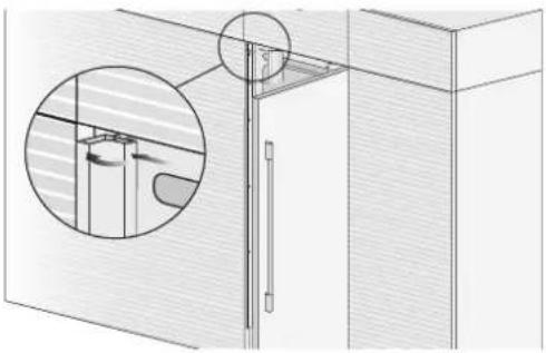
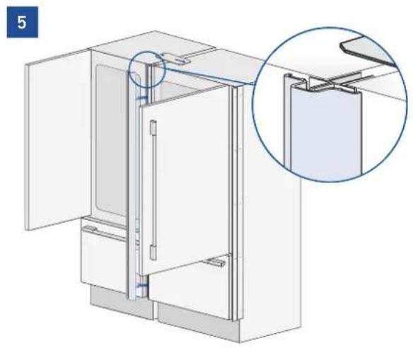
Diagram of a refrigerator interior showing door, cabinet, and shelf components with magnified views (no text or symbols)Finish off by mounting the central profile cover onto the central brackets, by pushing it until a click is heard [5].
natural_image
Technical illustration of a refrigerator with open door and internal compartments, showing a close-up detail (no text or symbols)Mount the covering frames onto the brackets used to join the units, first insert them laterally and then push firmly until a "click" is heard [8].

natural_image
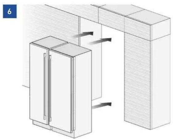
Architectural cross-section diagram of a building facade with two circular insets labeled 7 and 8 showing internal components (no text or symbols beyond labels)Once completed, push the units into their final position [6].
Always mount front panels on door before pushing the unit into its final position inside the cutout or structure.
Check the levelling of the appliance, adjusting its feet and wheels to correct it.
Secure the appliance to the adjacent cabinets by fixing with the supplied brackets on the appliance [7]. The door must be open to access the brackets for attachment to the cabinetry.

Take care as appliances will be front-heavy and may tip before they are secured to the adjacent furniture.
natural_image
Isometric line drawing of a cabinet and adjacent structure with directional arrows (no text or symbols)Side and central brackets mounting:
(Bird's eye view)
text_image
Appliance A A A B C A A B Wall or furnitureA - Plastic connecting brackets
B - Profile trim cover (side)
C - Profile trim cover (central)

6.3 Maximum cabinet depth over panel ready appliance with single door panel
It is possible that the design of the kitchen and, in particular, of the cutout where the panel ready appliance is going to be fitted includes a cabinet right above the refrigerator itself that must be closed with the same panel mounted on the panel ready refrigerator door.
In this case, the depth of the cabinet above the appliance must not exceed the depth of the appliance without the door [1].
This will allow the panel attached to the refrigerator door to open correctly without interference during its rotation up to 100^ .
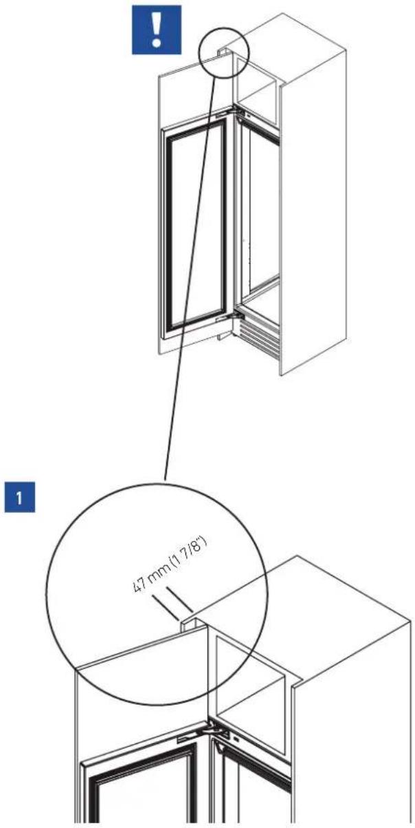
text_image
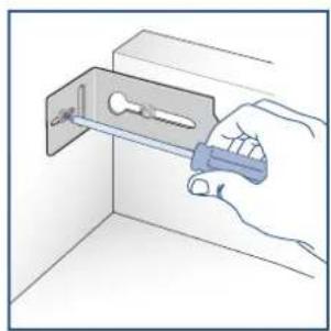
47 mm(1/7/8)7.1 Anti-tipping safety assembly

If the appliance(s) is not connected through the side profile trims to secured cabinetry you must install the anti-tip brackets to ensure the product does not fall forward during use and cause damage or injury. Failing to secure the appliance(s) securely will void any warranty claim attributable to a tipping situation.
Operate as follows:
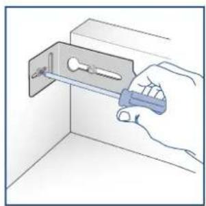
The brackets should be applied as illustrated using the provided screws If using the anti-tip brackets, lag into wood framing or concrete - drywall will not hold the weight of appliance.
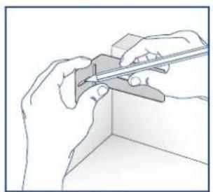
Place a bracket on the top of the appliance in correspondence to the fixing holes and against the wall [1].
1
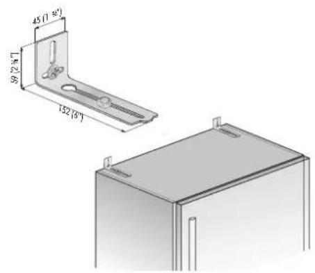
text_image
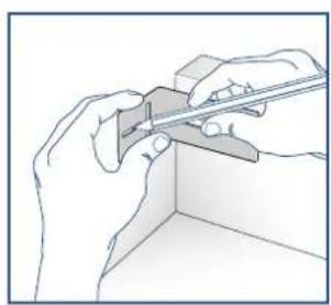
45 (1-30°) 39 (26°) 152 (8°)Mark up the holes position on the wall [2].
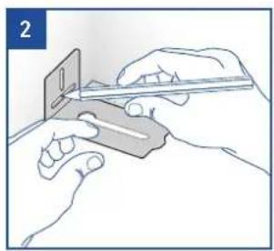
natural_image
Illustration of hands using a tool to cut a rectangular object (no text or symbols visible)BOTTOM COMPRESSORS UNIT
natural_image
Line drawing of hands using a tool to cut a rectangular object (no text or symbols)TOP COMPRESSORS UNIT
For concrete, drill the wall with an 8 mm (3/8") bit and insert the expansion plug [3].
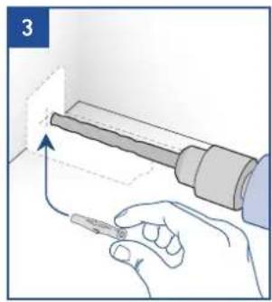
natural_image
Illustration of a hand holding a tool with an arrow indicating direction (no text or symbols)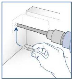
natural_image
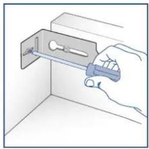
Hand holding a tool interacting with a mechanical component (no text or symbols visible)Reposition the bracket and fix it first to the appliance and then to the wall [4].
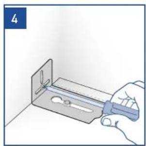
natural_image
Hand holding a tool interacting with a metal bracket (no text or symbols visible)BOTTOM COMPRESSORS MODEL
natural_image
Illustration of a hand using a tool to install a component into a wall-mounted bracket (no text or symbols)TOP COMPRESSORS MODEL

In order to use the anti-tip brackets on the top compressor models, it will be necessary to temporarily remove the top, metal ceiling / shield to access the bolting points for the brackets.
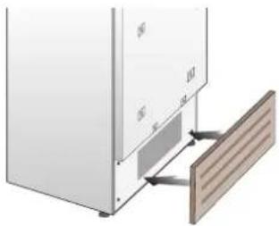
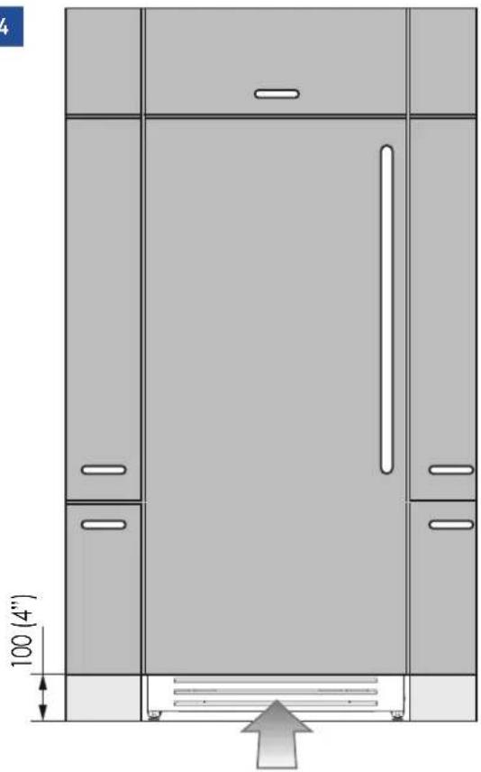
7.2 Ventilation
PANEL READY AND CLADDED MODELS
A forced air system assures ventilation through a grille, secured to the unit with magnetic plates, positioned in the lower front part of the unit [1].
1
natural_image
Diagram of a refrigerator with door, front panel, and side panel showing internal components (no text or symbols)If the kitchen cabinet includes a kickplate, it must be placed in a way to ensure optimal airflow [2].
2
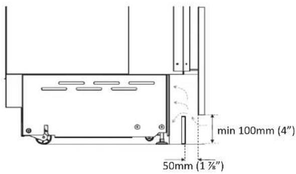
text_image
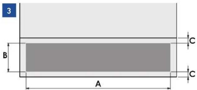
min 100mm (4") 50mm (1 ½") ?In case of placing a kickplate differently from picture [2], the kickplate must have vents / openings at least of an area equal to 50% of the area delimited by A and B dimensions in picture [3].
text_image
3 B A C C| 36" model 30" | model 24" model | ||
| A | 860 (33 7/8") 740 (29 1/8") 560 (22") | ||
| B > 100 (4") | |||
| C 10 (3/8") | |||
The condenser must to be cleaned on a regular basis. In order to do that, the front grille has to be accessible [4].
4
natural_image
Architectural diagram of a double-door cabinet with door, doors, and ventilation duct (no text or symbols)Stainless exterior Pro SERIES:
Ventilation is accomplished by a forced air system through a grille located in the upper part of the appliance. This grille should never be covered by panels or any other devices that could reduce its efficiency. Please refer to page Technical specifications sections for Stainless exterior Pro models to ensure correct air circulation.
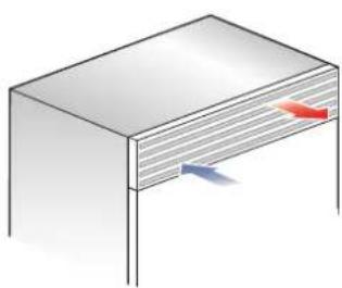
natural_image
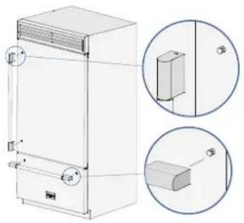
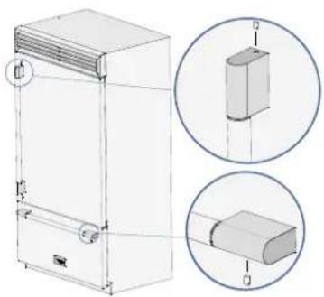
Illustration of a rectangular box with two colored arrows pointing downward (no text or symbols)7.3 Mounting the handles on cladded models

To mount the handles onto the door and the drawer operate as follows:
Operate as follows:
Insert the handle ends onto the supports already installed on the door and the drawer [1].
1
natural_image
Technical line drawing of a rectangular appliance with side views and mounting holes (no text or symbols)Screw in the set screws available on the handle [2].
2
natural_image
Technical line drawing of a refrigerant cabinet with two circular insets showing internal components (no text or symbols)The screws must be tightened in by means of a 2.5 mm (1/8") hex key or driver. It is recommended to use a thread-locking compound on the set screws to ensure they do not loosen over time / use.
7.4 Post installation checklist
√ Check that the front levelling feet have been properly installed.
√ Check that the connection to the water system does not have any leaks and that the shut-off valve is easily accessible.
√ Check that the electrical connection is correctly installed and that the socket and / or breaker are
easily accessible.
√ Check the perfect alignment of the appliance with adjacent structures.
√ Check that all adhesive tape and external or internal temporary protective devices have been removed.
√ Check the perfect closing of the doors and the smooth sliding of the drawers and shelves.
7.5 Start up
To turn on all the appliance compartments, press the Unit @button for three seconds. The display will show the message "Initial test" for approximately 2 minutes. After this phase the compressors will start up and remain on until the compartment set temperatures are achieved.
If the appliance is provided with an Ice Maker, prior to switching it on make sure that the water filter cartridge is installed (unless water supply source is already filtered by other means such as reverse osmosis).

text_image
FULGOR MEANO FULGOR MEANOPurge air from the water lines by performing the 'Manual Clean'. You may need to complete this sequence several times until you stop hearing air sputtering from the ice maker fill tube (Refer to your Use & Care Manual).
Once you are satisfied that the system is purged of air switch the Ice Maker on in the ice maker menu item of the appliance functions. Please refer to the Use & Care Manual for more details.
For further information about the appliance operation, refer to the User Manual.

If at the first start messages appear, such as Fridge too warm, Freezer too warm, or sound signals are activated, it means that the appliance has already previously started the cooling process.
If this is the case, deactivate any possible acoustic signals by pressing the Alarm
button, close the door and wait until the set temperature is reached. Allow the appliance to run / cool for at least 24 hours. If the set temperatures have not been achieved by 24 hours contact service.

It is necessary to let the unit reach the correct temperature before foods are stored inside.
Fulgor Milano is constantly researching new ways to improve the features and the design of their products, therefore models are often upgraded and revised and may not always appear as illustrated.
1 INDICATIONS IMPORTANTES 2
natural_image
Line drawing of a cabinet with chains wrapped around its lid (no text or symbols)text_image
mm (58 5/8") mm (52 5/8") mm (46 3/4") 992 (39") 100°text_image
min 10 (3/8")
text_image
Technical diagram showing a mechanical assembly with numbered components and magnified views of a component detail.natural_image
Architectural or engineering diagram showing structural components with no visible text or symbolsCOMPRESSEURS
AU-DESSUS
natural_image
Technical line drawing of a structural connection with labeled components (E and W), no readable text or symbols present.natural_image
Diagram showing a connector inserted into a housing with a cable, no text or symbols presentCOMPRESSEURS AU-DESSUS:
text_image
Diagram showing a device with labeled components and a magnified inset illustrating fluid flow or mechanical operation.natural_image
Simple 3D illustration of a person lying on a flat surface with a small object near the edge (no text or symbols)natural_image
Illustration of a hand holding a pen over a flat surface with a downward arrow, no text or symbols presentnatural_image
Illustration of a hand holding a ruler on a wooden surface, no text or symbols presenttext_image
Diagram showing a screwdriver inserted into a workpiece with numbered parts and alignment markersnatural_image
3D diagram of a screwdriver inserted into a flat surface with mounting holes and a numbered label '6' (no text or symbols on the diagram itself)natural_image
Technical line drawing of a two-tiered electrical cabinet with open doors (no text or symbols)| Modèle 36" Modèle 30" Modèle 24" | ||
| A 9 | 08 (35 3/4") 756 (29 3/4) 604 (23-3/4") | |
| B 4 | 17 (16 3/8") 342 (13 1/2") 276.5 (10 7/8") | |
| C 3 | 54.5 (14") 279.5 (11") 203.5 (8") | |
| D 3 | 68 (14 1/4") 302 (11 7/8") 235 (9 1/4") |

natural_image
Technical line drawing of a two-door refrigerator with front and side views (no text or symbols)| Modèle 24" | |
| A 604 (23-3/4") | |
| B 276.5 (10 7/8") | |
| C 203.5 (8") | |
| D 235 (9 1/4") | |

text_image
A 6.5 (1/4") 6.5 (1/4") 34 (1 3/8") min 1390 (54 3/4") 1286 (50 5/8") 1152.5 (45 3/8") 650.5 (25 5/8") 148.5 (5 7/8") B B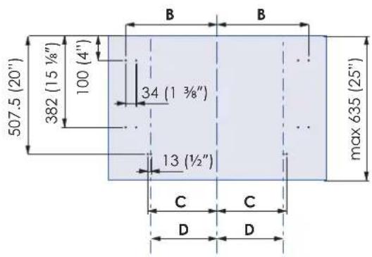
text_image
507.5 (20") 382 (15 ½") 100 (4") 34 (1 ¾") 13 (½") max 635 (25") B B C C D Dnatural_image
Illustration of a white rectangular cabinet with mounting holes and a separate panel showing internal structure (no text or symbols)natural_image
Pure electrical circuit lines without any symbolsnatural_image
Technical illustration of a rectangular enclosure with internal partitioned glass panels, showing mounting hardware (no text or symbols)| 24" | |
| A 604 (23 3/4") | |
| B 275 (10 7/8") | |
natural_image
Two gray rectangular blocks with a dimension label 'A' at the bottom (no text or symbols within the blocks)Panneau porte:
Largeur: 35-3/4"
Hauteur: 54-3/4"
Drawer panel:
Largeur: 35-3/4"
Hauteur: 84"-1/8"-54-3/4"-1/8"-4"=25"
If you want a 6" toe kick height then your bottom drawer panel height would be 23"
text_image
min 200 (7 7/8") 135 (5 3/8") 1075 (42 3/8") 135 (5 3/8") 115 (4 1/2") Bnatural_image
Simple gray rectangle with a labeled dimension 'A' at the bottom (no other text or symbols)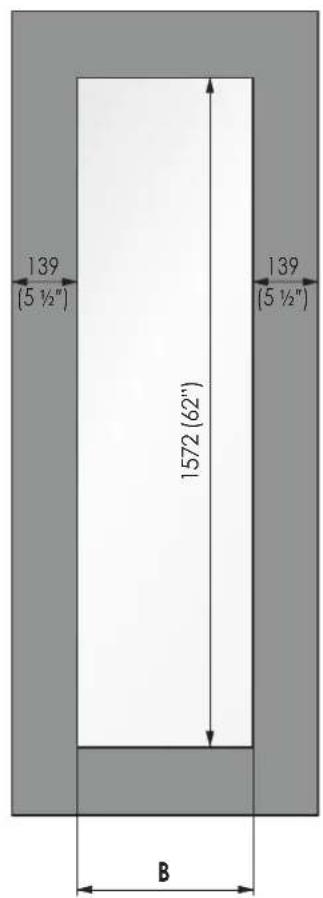
text_image
139 (5 ½") 1572 (62") B 139 (5 ½")text_image
Technical diagram of a refrigerator with labeled parts and zoomed-in detail viewnatural_image
Diagram of a faucet assembly with directional arrows indicating flow or movement (no text or symbols)text_image
Technical diagram of a refrigerator with labeled parts and close-ups showing internal components and assembly details
natural_image
Diagram showing a mechanical assembly with arrows indicating direction of motion (no text or symbols)natural_image
Diagram showing a device with mounting holes and a back panel, illustrating rotation and assembly (no text or symbols)natural_image
Pure diagram of a mechanical or fluidic component with directional arrows indicating flow or movement (no text or symbols)text_image
Diagram showing a wall-mounted device with labeled components and a magnified view of its internal structure with yellow tape.natural_image
3D architectural rendering of a cabinet with two doors and a shelf (no text or symbols)natural_image
Technical line drawing of a door frame with two circular insets showing internal components (no text or symbols)natural_image
Technical line drawing of a door assembly with a magnified inset showing internal components (no text or symbols)Plastic covering frames are provided for closing gaps between the appliance and the adjacent cabinets.
natural_image
Architectural line drawing of a cabinet and adjacent building (no text or symbols)natural_image
Technical line drawing of a server rack unit with an inset close-up showing internal components (no text or symbols)natural_image
Technical illustration of a refrigerator with labeled parts (no text or symbols present)natural_image
Technical line drawing of a refrigerator with an inset close-up showing internal components (no text or symbols)natural_image
Isometric line drawing of a kitchen appliance with doors and a cabinet, showing airflow direction (no text or symbols)
text_image
45 (1" 39 (2") 62 (6)natural_image
Illustration of hands using a tool to cut a rectangular object (no text or symbols visible)COMPRESSEURS EN DESSOUS
natural_image
Line drawing of hands using a caliper to measure a rectangular object in a corner (no text or symbols)COMPRESSEURS AU-DESSUS
natural_image
Illustration of a hand holding a tool with an arrow indicating direction (no text or symbols)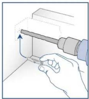
natural_image
Illustration of a hand using a tool to adjust or install a component, with no visible text or symbols.natural_image
Hand holding a blue tool applying material to a metal bracket (no text or symbols visible)COMPRESSEURS EN DESSOUS
natural_image
Illustration of a hand using a tool to install a component into a wall-mounted device (no text or symbols visible)COMPRESSEURS AU-DESSUS

natural_image
Diagram of a refrigerator with door panel and wooden shelf, no text or symbols presenttext_image
min 100mm (4") 50mm (1 ½")natural_image
Architectural diagram of a double door with cabinet, showing height dimension and support structure (no text or symbols)SÉRIE Stainless exterior Pro
natural_image
Illustration of a rectangular box with two colored arrows pointing downward (no text or symbols)natural_image
Technical line drawing of a rectangular appliance with two circular insets showing internal components (no text or symbols)natural_image
Technical line drawing of a rectangular industrial machine with two circular insets showing internal components (no text or symbols)text_image
FULCOR MEANO FULCOR MEANOnatural_image
Line drawing of a refrigerator with doors and hanging chain (no text or symbols)text_image
mm (58 5/8") mm (52 5/8") mm (46 3/4") 992 (39") 100°Distancia mínima de la pared (lado de la bisagra)
36" model: 160 mm (6 ¼")
30" model: 125 mm (5")
24" model: 90 mm (3 ½")
text_image
min 10 (3/8")
text_image
min 10 (3/8)
text_image
Technical diagram showing a mechanical assembly with numbered components and magnified views of a component detail.text_image
E W E W E W E W E W CONEXIONES ELÉCTRICA Y DEL AGUA
natural_image
Technical line drawing of a mechanical or architectural component with no visible text or symbolsTOP COMPRESSORS
UNIDAD
natural_image
Technical line drawing of a door frame structure with no visible text or symbolsnatural_image
Diagram of a mechanical component with threaded fitting and connecting rod, no text or symbols presentTOP COMPRESSORS UNIDAD:
natural_image
Diagram showing a kitchen appliance with a close-up inset of its interior components (no text or symbols)natural_image
Simple 3D illustration of a flat surface with a small white object on top, no text or symbols presentnatural_image
Diagram of a hand holding a pen on a flat surface with a downward arrow, no text or symbols presentnatural_image
Illustration of a hand drawing on a flat surface with a ruler, no text or symbols presenttext_image
Diagram showing a screwdriver inserted into a workpiece with numbered parts labeled 4 and 5natural_image
3D diagram of a mechanical assembly with a screwdriver and labeled components (no text or symbols)natural_image
Technical line drawing of a two-tiered electrical cabinet with mounting brackets (no text or symbols)| Modelo 36" Modelo 30" Modelo 24" | ||
| A 9 | 08 (35 3/4") 756 (29 | 3/4) 604 (23-3/4") |
| B 4 | 17 (16 3/8") 342 (13 | 1/2") 276.5 (10 7/8") |
| C 3 | 54.5 (14") 279.5 (11") | 203.5 (8") |
| D 3 | 68 (14 1/4") 302 (11 | 7/8") 235 (9 1/4") |

natural_image
Technical line drawing of a two-tiered stainless steel cabinet with front and side views (no text or symbols)| Modelo 24" | |
| A 597 (23 1/2") | |
| B 276.5 (10 7/8") | |
| C 203.5 (8") | |
| D 235 (9 1/4") | |

text_image
A 6.5 (1/4") 6.5 (1/4") 34 (1 3/8") min 1390 (54 3/4") 1286 (50 5/8") 1152.5 (45 3/8") 650.5 (25 5/8") 148.5 (5 7/8") B B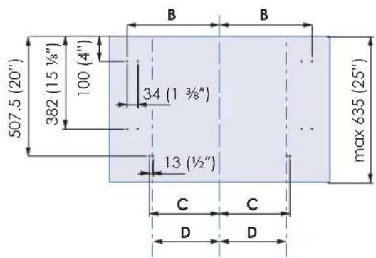
text_image
507.5 (20") 382 (15 1/8") 100 (4") 34 (1 3/8") max 635 (25") 13 (½") C C D Dnatural_image
Illustration of a white rectangular cabinet with side panels and mounting brackets, showing internal structure (no text or symbols)| Modelo 36" Modelo 30" Modelo 24" | ||
| A 9 | 08 (35 3/4") 756 (29 3/4") 604 (23-3/4") | |
| B 4 | 18 (16 1/2") 343 (13 1/2") 275 (10 7/8") | |
| D 3 | 68 (14 1/4") 302 (11 7/8") 235 (9 1/4") |

natural_image
Pure electrical circuit lines without any symbolsnatural_image
Technical illustration of a rectangular enclosure with internal partition and side panel (no text or symbols)| Modelo 24" | |
| A 6 | 04 (23 3/4") |
| B 2 | 75 (10 7/8") |
natural_image
Two gray rectangular blocks with a dimension label 'A' at the bottom (no other text or symbols)For fridge and freezer columns For wine columns
text_image
Technical diagram of a refrigerator with labeled parts and annotations, including zoomed-in detail and rotation mechanism.natural_image
Diagram of a faucet assembly with directional arrows indicating flow or movement (no text or symbols)text_image
Diagram of refrigerator interior showing door, shelf, and door panel with close-ups of components labeled 10 and 11
natural_image
Diagram showing a mechanical assembly with arrows indicating direction of motion (no text or symbols)natural_image
Diagram showing a device with mounting holes and a back panel, illustrating rotation and assembly (no text or symbols)natural_image
Pure mechanical diagram showing a lever and pipe connection without any text, numbers, or symbolstext_image
Diagram showing a microwave oven with labeled components and a magnified view of the internal structure with blue arrows indicating flow or movement.natural_image
Pure architectural line drawing of a cabinet or enclosure structure without any text, numbers, or symbolsnatural_image
Technical line drawing of a door frame assembly with two magnified views showing internal components (no text or symbols)natural_image
Technical line drawing of a door assembly with an inset showing a cylindrical component inserted into a housing (no text or symbols)natural_image
Isometric line drawing of a cabinet with doors and a shelf, no text or symbols presentnatural_image
Technical line drawing of a server rack unit with an inset close-up showing internal components (no text or symbols)natural_image
Technical illustration of a refrigerator with labeled parts (no text or symbols present)natural_image
Technical illustration of a refrigerator with open door and internal panel, showing close-up detail (no text or symbols)natural_image
Isometric line drawing of a kitchen appliance with doors and shelves, showing airflow direction (no text or symbols)text_image
Technical diagram showing two labeled components (7 and 8) with circular annotations highlighting structural details.
natural_image
Illustration of hands using a tool to cut or mark a metal component (no text or symbols visible)COMPRESOR INFERIOR

natural_image
Line drawing of hands using a tool to cut or inspect a component in a corner (no text or symbols)COMPRESOR SUPERIOR
natural_image
Illustration of a hand holding a tool with an arrow indicating direction (no text or symbols)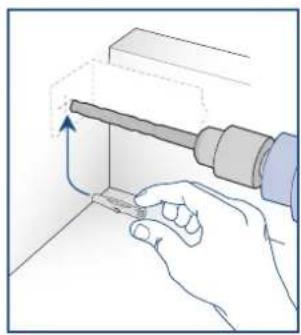
natural_image
Illustration of a hand using a tool to adjust or install a component, with no visible text or symbols.natural_image
Hand holding a tool interacting with a metal bracket (no text or symbols visible)COMPRESOR INFERIOR
natural_image
Illustration of a hand using a tool to install a component into a wall-mounted panel (no text or symbols visible)COMPRESOR SUPERIOR