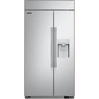
SKSSB4202S - Fridge SKS - Free user manual and instructions
Find the device manual for free SKSSB4202S SKS in PDF.


| Product type | Built-in American-style refrigerator |
| Brand | SKS |
| Model | SKSSB4202S |
| Dimensions (W × H × D) | 1067 × 2121 × 645 mm |
| Power supply | 115 V, 60 Hz |
| Ice maker | Yes, with built-in water dispenser |
| Water dispenser | Yes, with internal tank |
| Maximum door opening | 130 degrees |
| Door hold at 90° | Fixing device included |
| Door height adjustment | Up to 3 mm per door |
| Lateral door adjustment | Up to 3.9 mm per door |
| Leveling | Adjustable front and rear feet |
| Anti-tilt device | Fixing brackets included |
| Water connection | Required, 5/16" (8 mm) copper pipe recommended |
| Installation type | Built-in (or standard) |
| Recommended cutout dimensions (W × H × D) | Standard installation: 610 × 2127 × 1054 mm; Built-in: 660 × 2127 × 1070 mm |
| Included accessories | Screws M4×12, M4×22, anti-tilt brackets, door hold device |
| Safety | Grounding required; avoid multiple outlets |
| Maintenance | Clean door seals and lower grille regularly |
Frequently Asked Questions - SKSSB4202S SKS
User questions about SKSSB4202S SKS
0 question about this device. Answer the ones you know or ask your own.
Ask a new question about this device
Download the instructions for your Fridge in PDF format for free! Find your manual SKSSB4202S - SKS and take your electronic device back in hand. On this page are published all the documents necessary for the use of your device. SKSSB4202S by SKS.
USER MANUAL SKSSB4202S SKS
Copyright © 2022 Signature Kitchen Suite. All Rights Reserved.
2
Contents
- Precaution before installation.... 3
- Product and Cutout dimension 4
- Precaution when moving the product....5
- Cabinet diagram and maximum door opening....6
- Refrigerator/Freezer door opening and how to fix at 90 degrees.....7
- Installation of part to prevent the product from falling over....7
- Connecting power and securing space for water supply pipe....9
- How to install the water supply pipe 10
- Product detail dimension.... 11
- Cabinet detail dimension.... 12
- How to adjust the height of the refrigerator and freezer door.... 14
- How to adjust the height of the product....15
- How to disassemble/reassemble the top grill 16
- Left/Right door adjuster for refrigerator and freezer 17

1. Precaution before installation

WARNING
TIP-OVER HAZARD
Use two or more people to move and install the refrigerator. To prevent the refrigerator from tipping over, install anti-tip brackets (provided). Failure to follow the refrigerator installation instructions can result in serious injury or death.


Precaution
■ Install the product away from the heat of the heater, boiler or direct sunlight. Install the product where air flows well and is well ventilated.
■ Refer to the dimension of the cabinet and prepare the cabinet with good air circulation. Install the product so that air flows smoothly through the front air inlet. If the air circulation structure is not ensured, it may interfere with the normal operation of the product.
■ Because the damage to the power cord from external animals (Rodents) can cause a fire, install the product where there is no access from external animals.
■ If the cabinet is made of soft material (Ex: Plaster etc.), it can have week assembly force or even can be damaged. Therefore use the cabinet made of firm strong material.
■ Use cabinet without any twisting from the heat emitted from the product or humidity from the opening and closing of the refrigerator.
■ Install the product where it is leveled horizontally and vertically. (Within 1mm horizontally and vertically) If the product is not leveled horizontally and vertically, it can be difficult to install the product. (The cabinet must be made of material or must be in the structure not to cause continuous deformation when 220.5 lb(100kg) of load is applied.)
■ Install the built-in refrigerator with a team of 2 people.
■ When installing the product, protect the children from the use of parts and installation location.
■ During the installation, take out the screw from the plastic bag one by one to avoid any injury from exposed parts.
■ Avoid the use of multi-tab as it can cause a fire.
■ Before installing the product, connect the product to make sure to check it is operating normally.
2. Product and Cutout dimension
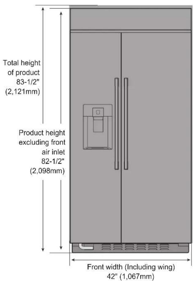
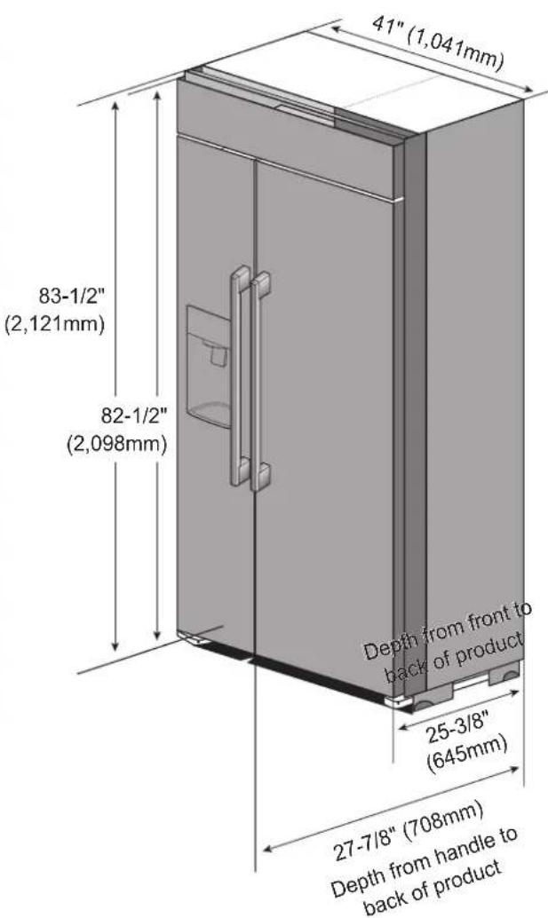
- Product dimension (In) : 42"(1,067mm) x 83-1/2"(2,121mm) x 25-3/8"(645mm) (W x H x D)
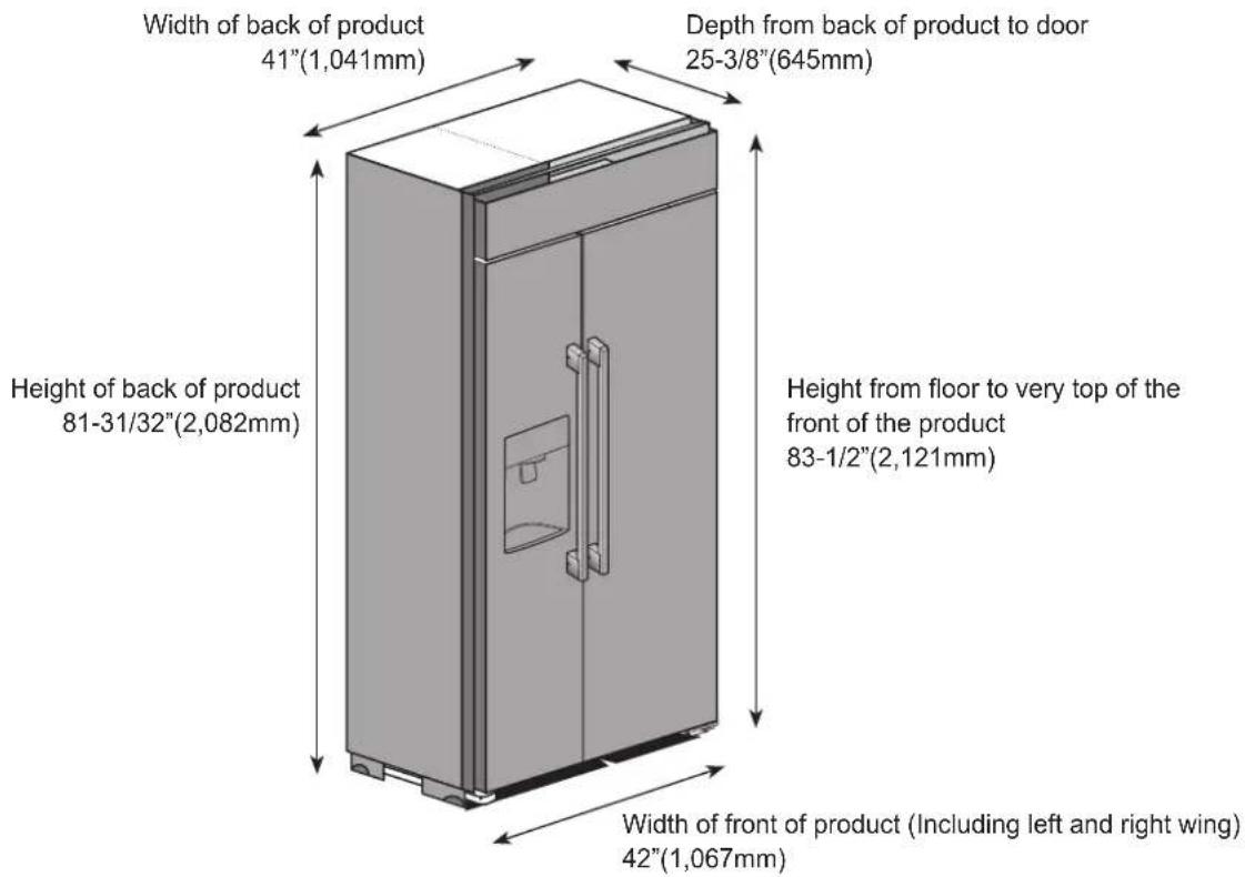
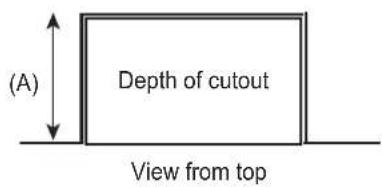
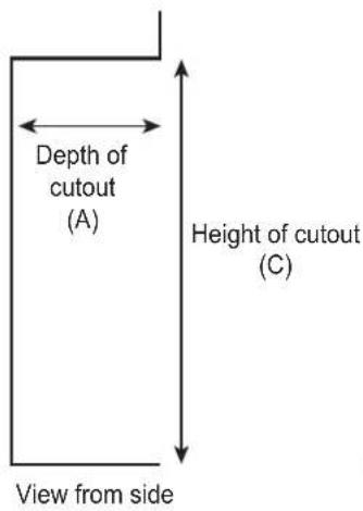
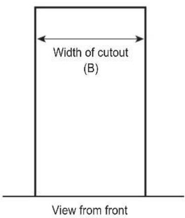
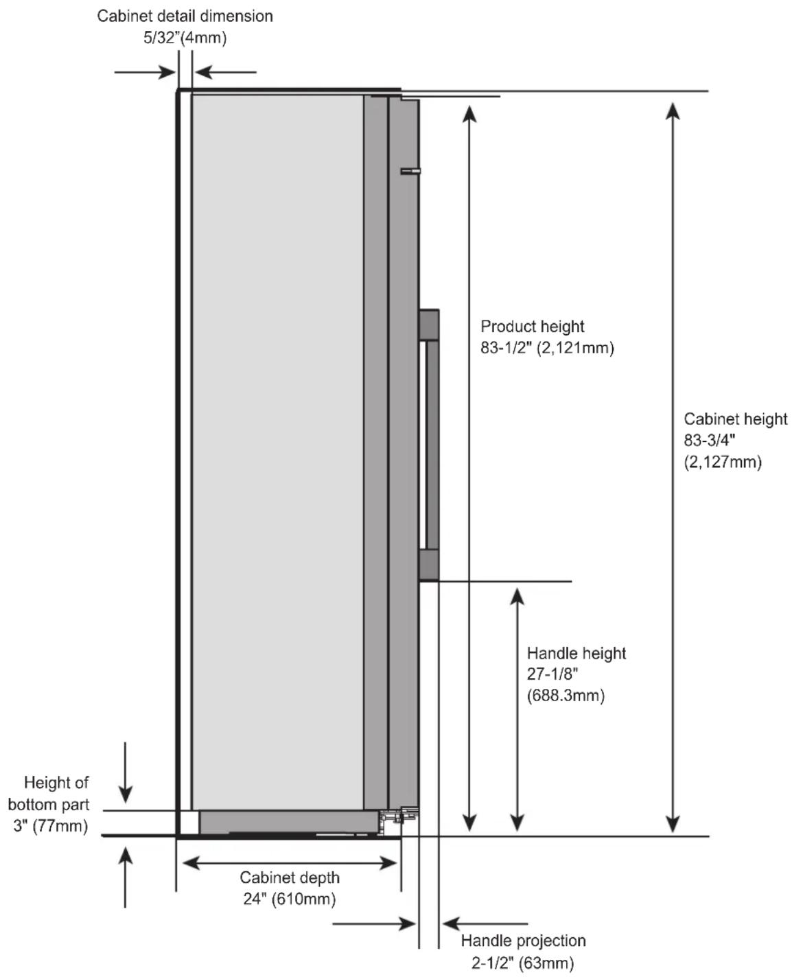
- Cutout dimension for product installation (In)
Standard Installation : 41-1/2"(1,054mm) X 83-3/4"(2,127mm) X 24"(610mm) (W x H x D)
Flush Installation : 42-1/8"(1,070mm) X 83-3/4"(2,127mm) X 26"(660mm) (W X H x D)
Check the dimension of the cutout to install the product against the dimension stated in the installation manual. The dimensions are the recommended dimensions to install the product. (If the cutout dimension is smaller than the recommended dimension, the product cannot be installed.)
| Standard Installation | Flush Installation | |
| A 24" (610mm) | 26"(660mm) | |
| B 41-1/2"(1,054mm) | 42-1/8"(1,070mm) | |
| C 83-3/4"(2,127mm) | ||
3. Precaution when moving the product
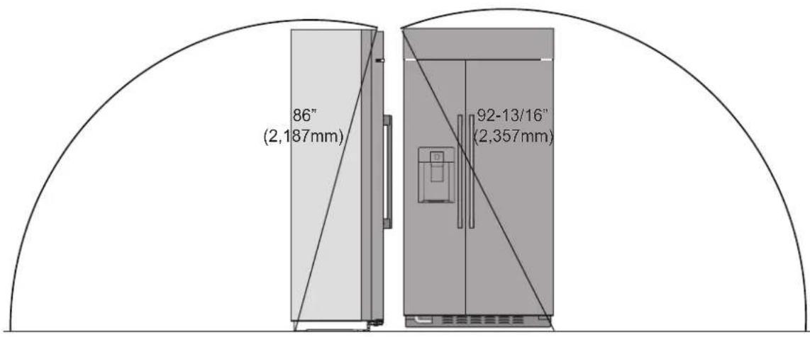
■ Before moving the refrigerator, check the line of movement to the location to install. (Refer to the product dimension and rotating radius.)
1) Request the installation to the specialized technician.
It can cause electric shock, fire, malfunction and explosion.
2) Due to the characteristics of the built-in product, the top is heavy and can easily fall over when not installed. Therefore be careful when moving the product. Also because the product can be dangerous if left on inclined surface, always keep the product fixed or held.
4. Cabinet diagram and maximum door opening
4-1. Standard Installation
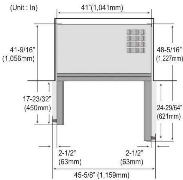
< Dimension when opening 90 degrees >
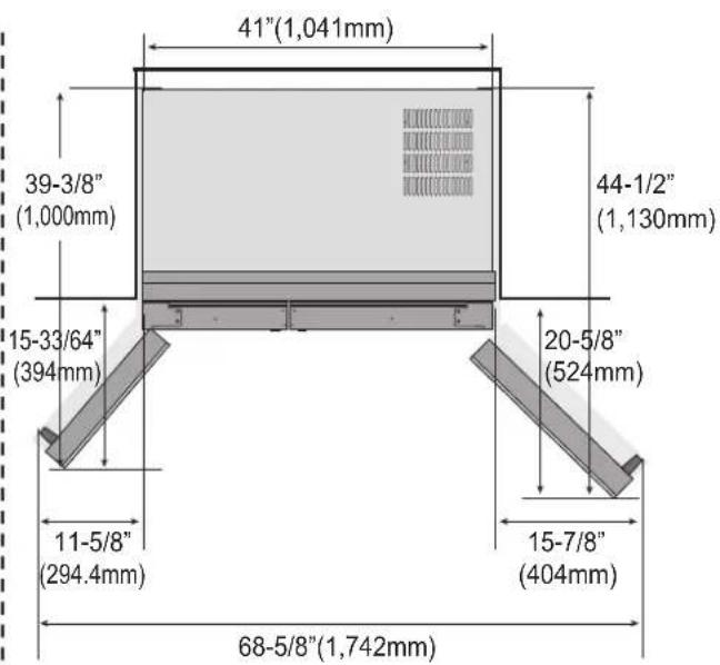
< Dimension when opening 130 degrees >
4-2. Flush Installation
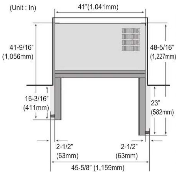
< Dimension when opening 90 degrees >
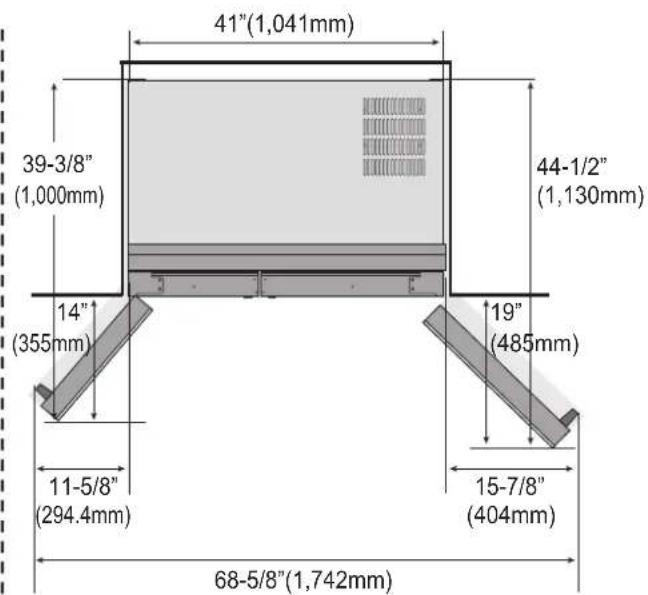
< Dimension when opening 130 degrees >
When installing the product on the wall near the corner, check the marked dimension to keep minimum distance to avoid the handle hitting the wall.
5. Refrigerator/Freezer door opening and how to fix at 90 degrees
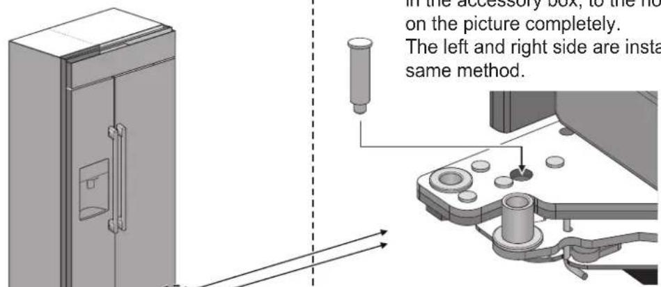
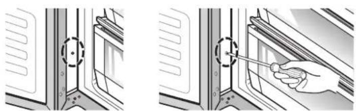
Push and install the device to keep the refrigerator door open and fixed, included in the accessory box, to the hole marked on the picture completely.
The left and right side are installed in the same method.
※ If the device to keep the refrigerator door open and fixed cannot be inserted, move the refrigerator door slowly in left and right direction to push it in.
6. Installation of part to prevent the product from falling over
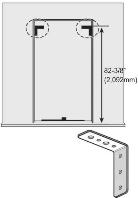
Part to prevent product from falling over x 2
※ Because the built-in product is heavy on the top, the cabinet must be fixed firmly so that the product does not move when using it.
- Fix the side of the cabinet to the building wall or side of the furniture firmly.
- Use the part included in the accessory box as shown in the picture to fix the cabinet to both sides of the walls.
- If the part prevent the product from falling over is not installed in the correct location, the product can fall over to cause severe injury or death.
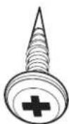
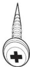
M4*L12 screw x 6 M4*L22 screw x 8
Spare screws may be included
6. Installation of part to prevent the product from falling over
1) Check if all the described parts are included in the accessory box.
2) Based on the recommended dimension on the picture, place the part to prevent the product from falling over. (Same for both left and right side)
3) Use the M4*L12 screw included in the accessory box to tighten 3 locations respectively on left and right side.
(Tighten the screws completely so that the part is not loose from the cabinet.)
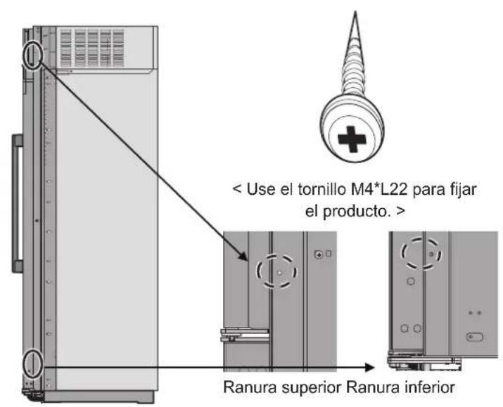
4) Place the product on the cabinet and then use the M4*L22 screw included in the accessory box to tighten 4 locations respectively on left and right side on the groove marked on the picture after checking whether the product is leveled and checking the level difference between the refrigerator and freezer door and the alignment between the front part of the product against the cabinet etc.
(When inserting the refrigerator in the cabinet, be careful not to get the hand caught.)
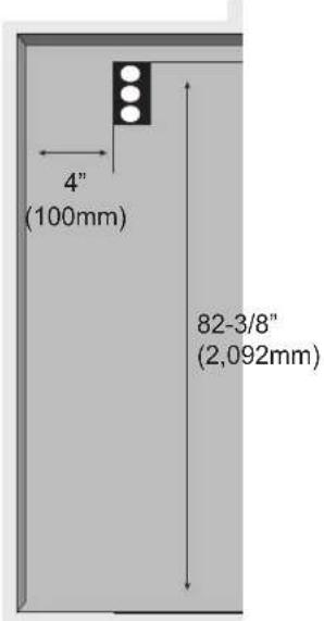
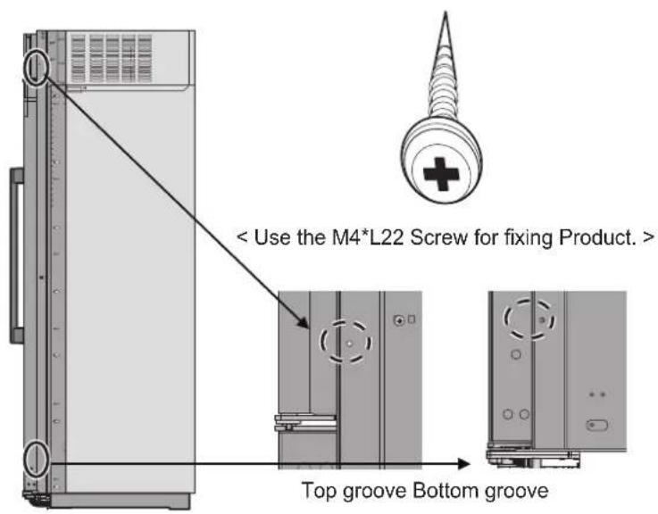
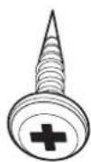
< Use the M4*L12 Screw for fixing anti tip over bracket. >
natural_image
Illustration showing two steps of a door opening process: one with a screwdriver inserted, the other with a screwdriver inserted (no text or symbols present)7. Connecting power and securing space for water supply pipe
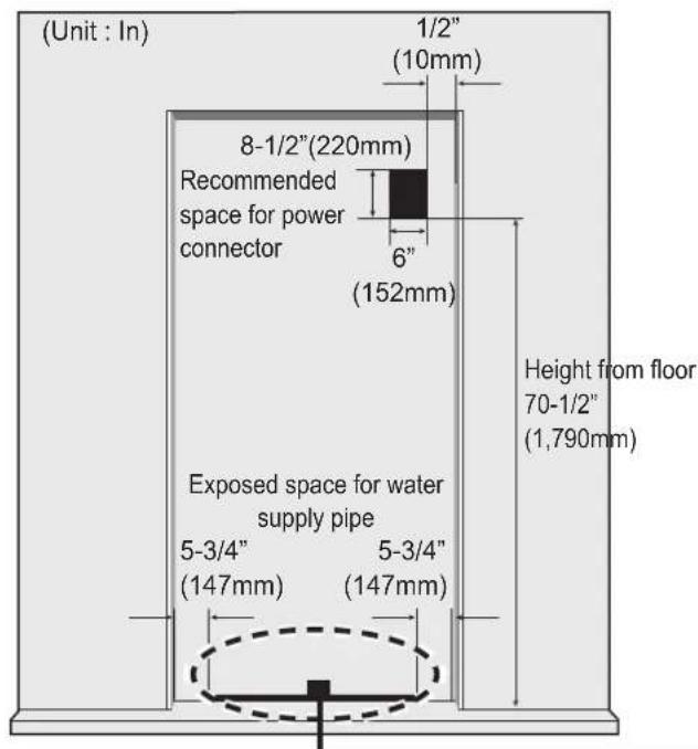
- Power connection The location of the 115V 60Hz power connector must be located on the rear side of the product as shown in the picture.
When installing the product, make sure to check whether the cord is hung on the hook on the rear side so that it is not pressed on the refrigerator. Damaged power cord can cause a fire.
- Installation space for water supply pipe
Place the water hose for ice maker and water dispenser as shown in the picture, and prepare hose to come up from the floor.
(Copper pipe with diameter of 5/16"(8mm) is recommended for the water hose.)
If the water pipe and water hose is located far from the product, bury the water hose
on the floor and provide appropriate treatment.
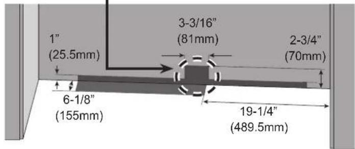
Make sure the location of the water supply pipe is within the marked range.
Before connecting the power, always make sure to ground the product. (If the product is not grounded, the user may be able to feel the electricity due to the minute leakage current when touching the refrigerator door handle or side corner even when there is no issue with the product.)
Do not ground the product to gas pipe, plastic water pipe or telephone wire etc. It can cause electric shock and explosion.
8. How to install the water supply pipe
natural_image
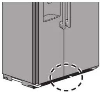
Diagram of a refrigerator interior showing door, doors, and base (no text or symbols)* Check the location and installation detail of the water service pipe on the previous page before connecting the water supply pipe. Before inserting the product completely into the cabinet, check if there is any water leakage.
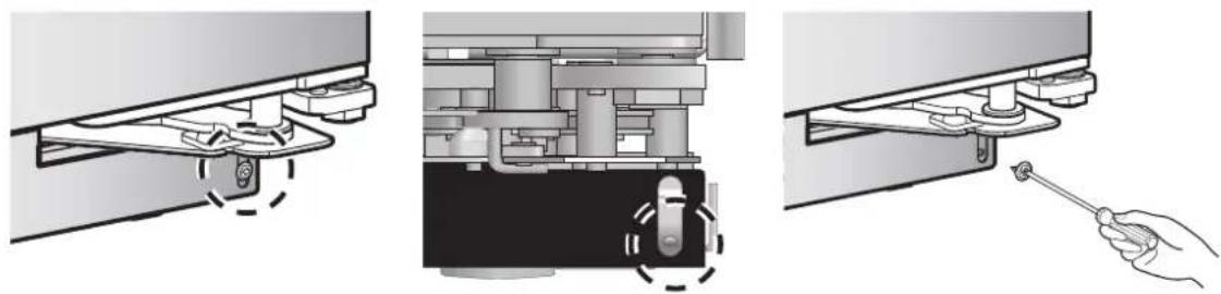
1) Disassemble the bottom grill.
(Both the left and right sides are disassembled and reassembled in the same method.)
- Use the (+) driver to disassemble the bottom grill.
natural_image
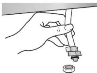
Three-step diagram showing mechanical assembly with a hand holding a wrench, no text or symbols present2) Pull out the water supply pipe from the bottom of the product and prepare to disassemble/reassemble the connecting part of the water service pipe.
natural_image
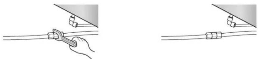
Hand holding a tool with a nut inserted, no text or symbols visible3) After connecting the water supply pipe and the water service pipe, tighten them with a spanner to avoid any leakage. After installing the product within the cabinet, recheck for any water leakage.
* Prepare a bucket under the water service pipe connector before checking for any water leakage to avoid ruining the flooring material and carpet etc.
natural_image
Illustration showing a hand using a tool to connect two cables, with no text or symbols present.4) Reassemble the bottom grill in the reverse order of 1).
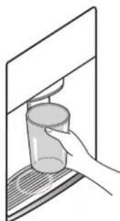
5) Flush air from the system by running water through the dispenser continuously for 5 gallon.
Note: Allow 1\~2 minute delay in water dispersal to allow internal water tank to fill.
natural_image
Hand placing a glass container into a rectangular frame (no text or symbols visible)9. Product detail dimension
ENGLISH
10. Cabinet detail dimension
10-1. Standard Installation
10-2. Flush Installation
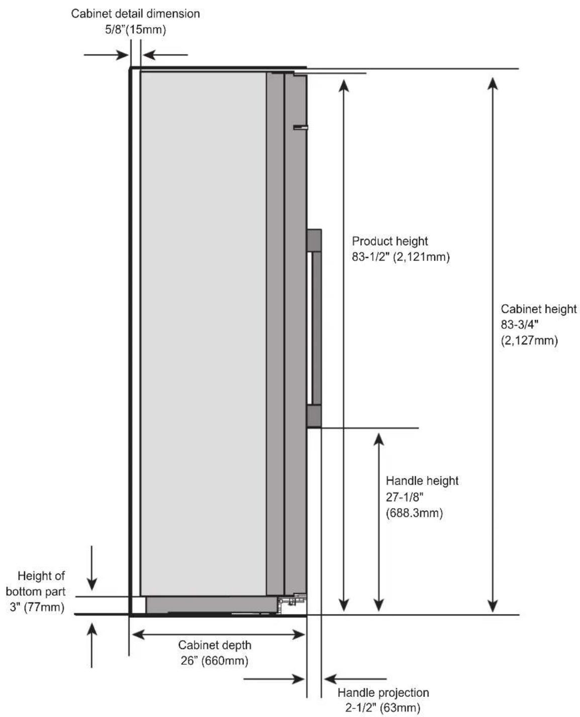
11. How to adjust the height of the refrigerator and freezer door
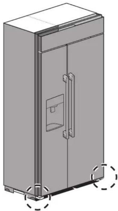
natural_image
3D technical illustration of a double door with handle and mounting base (no text or symbols)1) If the height of the refrigerator and freezer is different, turn the bottom door height adjustment bolt to adjust the height.
- The refrigerator and freezer door can be adjusted by 1/8"(3mm) respectively.
- M6 wrench to adjust the height of the door is not included in the accessory box. (For accurate height adjustment, it is recommended to contact the service center.)
※ If the height of the door is adjusted excessively on left/right side, the door close sensor may not recognize well and the door may not be closed.
2) Adjustment order (Adjustment method is same for both left and right side.)
- Loosen the nut to prevent it from loosening. (Using Spanner.)
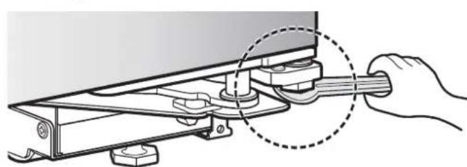
natural_image
Diagram of a hand using a wrench to adjust or install a mechanical component, with no visible text or symbols.
natural_image
Mechanical assembly diagram showing a clamping mechanism with no visible text or symbols* It is convenient to use the small hole on the back of the spanner included in the accessory box.
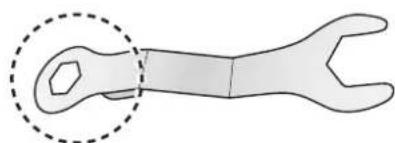
natural_image
Technical line drawing of a wrench with a dashed circular annotation highlighting the handle (no text or symbols present)- Use the M6 wrench to adjust the height. (Turn clockwise to raise the refrigerator door.)
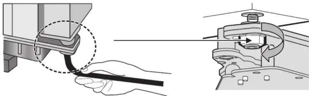
natural_image
Technical illustration showing a hand holding a cable being inserted into a mechanical component (no text or symbols present)12. How to adjust the height of the product
natural_image
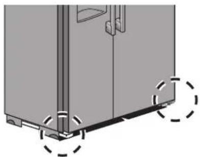
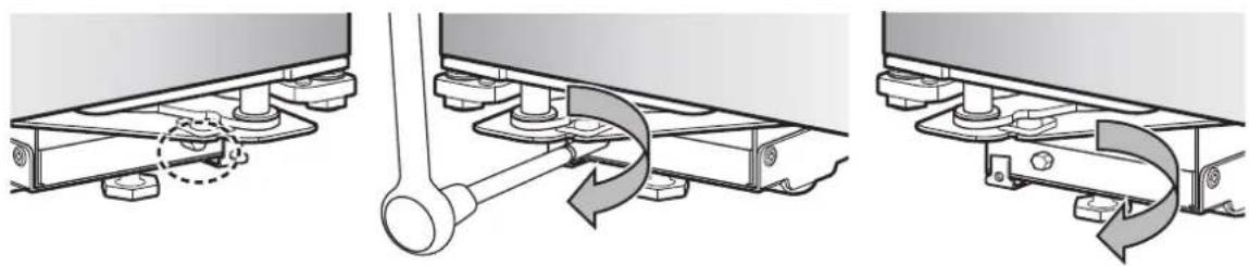
Diagram of a refrigerator with door and side panel, showing mounting base and door handle (no text or symbols)1) Use the height adjuster on the front/rear side to level the product and adjust the height on both left and right side.
* For built-in product, adjust the height of and level the product during the initial installation.
(For accurate height adjustment, it is recommended to contact the service center.)
2) Adjustment order (Adjustment method is same for both left and right side.)
-. Disassemble the bottom grill using the (+) driver.
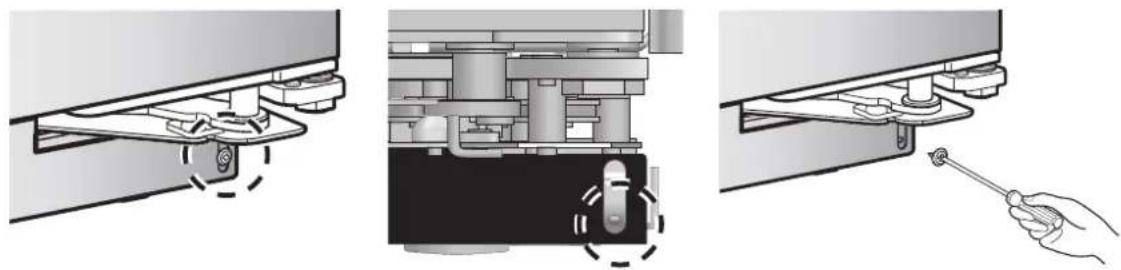
natural_image
Three-step diagram showing mechanical assembly with a hand holding a wrench, no text or symbols present- Use the front height adjuster to adjust the height. (Turn clockwise to raise the product.)
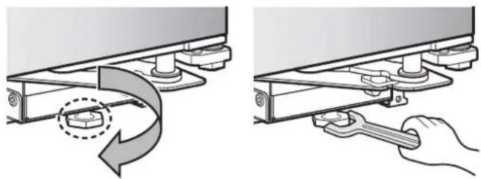
natural_image
Two-step diagram showing a mechanical device with a rotating arrow and a hand holding a wrench (no text or symbols)- Use the M8 spanner to adjust the height adjuster on the rear side. (Turn clockwise to raise the product.)
natural_image
Three mechanical assembly diagrams showing lever mechanism and rotation arrows (no text or symbols)※ M8 spanner is not included in the accessory box.
3) After adjusting the height, always make sure to install the bottom grill.
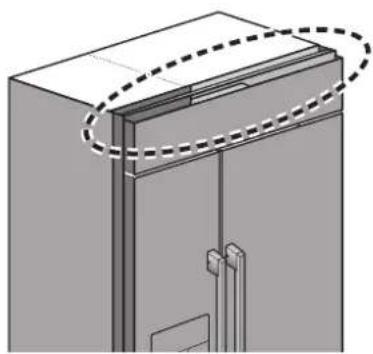
13. How to disassemble/reassemble the top grill
natural_image
3D diagram of a cabinet or enclosure with dashed lines indicating alignment or measurement (no text or symbols present)1) To adjust the left/right door, the top grill must be disassembled first.
※ Because the corners can be sharp, make sure to be careful during the task.
※ After disassembling the top grill, place it at a safe location to avoid any scratch on the panel.
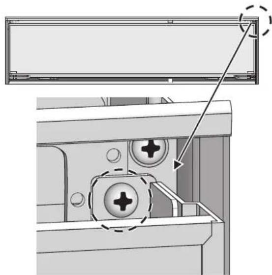
2) Top grill disassembly and reassembly order
- Loosen the indicated screws and keep them safely. (Left and right are symmetrical)
natural_image
Technical diagram showing a mechanical assembly with mounting holes and a dashed circular annotation (no text or symbols)- Lift up the top grill as shown in the picture to pull it out to the front.
※ For the safety of the customer, there is a hook on the left/right side of the top grill. If the part is separated with excessive force, it can cause an injury.
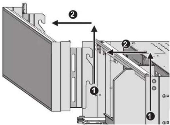
-. Reassembly can be done in the reverse order.
14. Left/Right door adjuster for refrigerator and freezer
1) The gap between the refrigerator and freezer is 5/16"(8mm) by factory default. If the gap between the refrigerator and freezer door changes during the product installation, use the left/right door adjuster to maintain the gap.
- The refrigerator and freezer door can be adjusted by 5/32"(3.9mm) respectively.
- M10 spanner for left/right adjustment is not included in the accessory box.
(For accurate left/right adjustment, it is recommended to contact the service center.)
2) Adjustment order
▶ Refrigerator left/right door adjuster
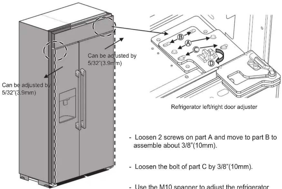
- Loosen 2 screws on part A and move to part B to assemble about 3/8"(10mm).
- Loosen the bolt of part C by 3/8"(10mm).
- Use the M10 spanner to adjust the refrigerator left/right for part D.
* When part D is rotated 2 times, the refrigerator door must move by 1/32"(1mm).
※ When part D is turned counterclockwise, the product moves toward the outer side.
14. Left/Right door adjuster for refrigerator and freezer
2) Adjustment order
▶ Refrigerator door left/right adjuster
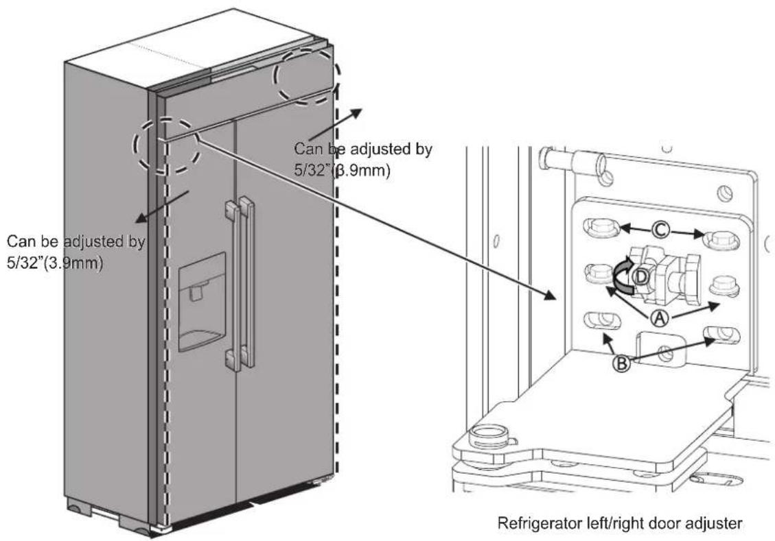
- . Loosen 2 screws on part A and move to part B to assemble about 3/8"(10mm).
-. Loosen the bolt of part C by 3/8"(10mm). - . Use the M10 spanner to adjust the Freezer left/right for part D.
※ When part D is rotated 2 times, the Freezer door must move by 1/32"(1mm).
* When part D is turned counterclockwise, the product moves toward the outer side.
SIGNATURE
KITCHEN SUITE
P/No.: MFL67410837_Rev.02
www.signaturekitchensuite.com
Installation standard : 41-1/2" (1 054 mm) X 83-3/4" (2 127 mm) X 24" (610 mm) (L x H x P)
Installation encastrée : 42-1/8"(1 070 mm) X 83-3/4"(2 127mm) X 26"(660 mm) (W X H x D)
natural_image
Technical line drawing of a refrigerator with door and side-mounted door (no text or symbols)natural_image
Mechanical assembly diagram showing a tool interacting with a mechanical component (no text or symbols visible)natural_image
Illustration showing two steps of installing or adjusting a door panel, with no visible text or symbols.natural_image
Diagram of a refrigerator interior showing door, doors, and base (no text or symbols)natural_image
Three-step diagram showing mechanical assembly with a wrench inserted, no text or symbols presentnatural_image
Hand holding a mechanical component with a nut, no text or symbols visible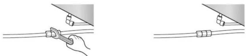
natural_image
Illustration showing two methods of connecting wires with a hand using a tool (no text or symbols present)natural_image
Illustration of a hand pouring liquid into a glass container on a surface (no text or symbols)natural_image
3D technical illustration of a cabinet with door and handle (no text or symbols)natural_image
Illustration of a hand using a wrench to adjust or install a mechanical component (no text or symbols present)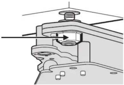
natural_image
Mechanical assembly diagram showing a clamping mechanism with no visible text or symbolsnatural_image
Line drawing of a wrench with a dashed circular annotation (no text or symbols)natural_image
Technical illustration showing a hand holding a cable being inserted into a mechanical component, with no visible text or symbols.natural_image
Diagram of a refrigerator with door and side-mounted legs, showing mounting feet and dashed circular annotations (no text or symbols)natural_image
Three-step diagram showing mechanical assembly with a hand holding a wrench, no text or symbols presentnatural_image
Two-step diagram showing a mechanical assembly with a hand operating a wrench to adjust the component (no text or symbols present)natural_image
Three-step diagram showing mechanical assembly with rotating components and a tool (no text or symbols)natural_image
3D diagram of a door with dashed lines indicating alignment or measurement (no text or symbols)natural_image
Technical diagram showing a mechanical assembly with mounting holes and a dashed line indicating a dimension (no text or symbols present)P/No.: MFL67410837_Rev.02
natural_image
Illustration showing two steps of installing or adjusting a door panel, with no visible text or symbols.natural_image
3D diagram of a refrigerator with door and side-mounted legs, showing no text or symbolsnatural_image
Three-step diagram showing mechanical assembly with a hand holding a wrench, no text or symbols presentnatural_image
Hand holding a tool with a small component inserted, no text or symbols visiblenatural_image
Illustration showing two different cable installation techniques: one using a tool to connect wires, the other with a coiled cable (no text or symbols present)natural_image
Hand pouring liquid into a glass container on a surface (no text or symbols visible)natural_image
3D technical illustration of a door with handle and mounting base, showing internal structure (no text or symbols)natural_image
Diagram of a hand using a wrench to adjust or install a mechanical component, with no visible text or symbols.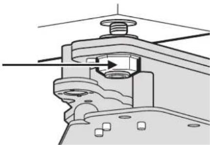
natural_image
Mechanical assembly diagram showing a valve mechanism with no visible text or symbolsnatural_image
Diagram of a wrench with a dashed circular outline highlighting the handle (no text or symbols)natural_image
Technical illustration showing a hand holding a cable being inserted into a mechanical component (no text or symbols present)natural_image
Diagram of a refrigerator with door and side-mounted legs, showing mounting feet and dashed circular annotations (no text or symbols)natural_image
Three-step diagram showing mechanical assembly with a hand holding a wrench, no text or symbols presentnatural_image
Two-step diagram showing a mechanical device with a rotating arrow and a hand holding a wrench (no text or symbols)natural_image
Three mechanical assembly diagrams showing a lever mechanism with curved arrows indicating motion (no text or symbols present)natural_image
Diagram of a door with dashed lines indicating alignment or measurement, no text or symbols presentnatural_image
Technical diagram showing a mechanical assembly with mounting holes and a dashed line indicating a detail (no text or symbols present)



- Contents
- Precaution before installation
- WARNING
- TIP-OVER HAZARD
- Precaution
- Product and Cutout dimension
- Precaution when moving the product
- Cabinet diagram and maximum door opening
- 4-1. Standard Installation
- 4-2. Flush Installation
- Refrigerator/Freezer door opening and how to fix at 90 degrees
- Installation of part to prevent the product from falling over
- Connecting power and securing space for water supply pipe
- How to install the water supply pipe
- Product detail dimension
- Cabinet detail dimension
- 10-1. Standard Installation
- 10-2. Flush Installation
- How to adjust the height of the refrigerator and freezer door
- How to adjust the height of the product
- How to disassemble/reassemble the top grill
- Left/Right door adjuster for refrigerator and freezer
- SIGNATURE
- KITCHEN SUITE
Brand : SKS
Model : SKSSB4202S
Category : Fridge