B900 - Basket Air King - Free user manual and instructions
Find the device manual for free B900 Air King in PDF.


User questions about B900 Air King
0 question about this device. Answer the ones you know or ask your own.
Ask a new question about this device
Download the instructions for your Basket in PDF format for free! Find your manual B900 - Air King and take your electronic device back in hand. On this page are published all the documents necessary for the use of your device. B900 by Air King.
USER MANUAL B900 Air King
IMPORTANT INSTRUCTIONS - OPERATING MANUAL
Models: B900, B1125

text_image
AirKing Ventilation Products®Profesional Series Blower

READ AND SAVE THESE INSTRUCTIONS
READ CAREFULLY BEFORE ATTEMPTING TO ASSEMBLE, INSTALL, OPERATE OR MAINTAIN THE PRODUCT DESCRIBED. PROTECT YOURSELF AND OTHERS BY OBSERVING ALL SAFETY INFORMATION. FAILURE TO COMPLY WITH INSTRUCTIONS COULD RESULT IN PERSONAL INJURY AND/OR PROPERTY DAMAGE!

RETAIN INSTRUCTIONS FOR FUTURE REFERENCE.
GENERAL SAFETY INFORMATION

When using electrical appliances, basic precautions should always be followed to reduce the risk of fire, electric shock and injury to person, including the following:


WARNING: THIS BLOWER ASSEMBLY MUST BE INSTALLED WITH TRANSFORMER ASSEMBLY MODEL XFMR129:

WARNING: TO REDUCE THE RISK OF FIRE, ELECTRIC SHOCK AND INJURY TO PERSON, OBSERVE THE FOLLOWING:
a) Use this unit only in the manner intended by the manufacturer. If you have questions, contact the manufacturer.
b) Before servicing or cleaning the unit, switch power off at service panel and lock the service disconnecting means to prevent power from being switched on accidentally. When the service disconnecting means cannot be locked, securely fasten a prominent warning device, such as a tag, to the service panel.

WARNING: TO REDUCE THE RISK OF FIRE, ELECTRIC SHOCK AND INJURY TO PERSON, OBSERVE THE FOLLOWING:
a) Installation work and electrical wiring must be done by qualified person(s) in accordance with all applicable codes and standards, including fire-related construction.
b) Sufficient air is needed for proper combustion and exhausting of gases through the flue (chimney) of fuel burning equipment to prevent back drafting. Follow the heating equipment manufacturer's guideline and safety standards such as those published by the National Fire Protection Association (NFPA) and the American Society for Heating, Refrigeration, and Air Conditioning Engineers (ASHRAE), and the local code authorities.


CAUTION: FOR GENERAL VENTILATING USE ONLY. DO NOT USE TO EXHAUST HAZARDOUS OR EXPLOSIVE MATERIALS AND VAPORS.
c) To avoid motor bearing damage and noisy and/or unbalanced impellers, keep drywall spray, construction dust, etc. off power unit.
d) Read all instructions before installing or using range hood.
e) Refer to the instructions included with the Range Hood Canopy for additional safety information.
INSTALLATION INSTRUCTIONS


CAUTION: MAKE SURE POWER IS SWITCHED OFF AT SERVICE PANEL BEFORE STARTING INSTALLATION.

WARNING: THIS BLOWER IS INTENDED FOR USE ONLY IN AIR KING PROFESSIONAL SERIES RANGEHOOD CANOPIES MARKED SUITABLE FOR USE WITH THIS BLOWER. DO NOT INSTALL IN ANY OTHER APPLICATION.
SECTION 1
Preparing for installation
NOTE: Before installing blower, make sure range hood canopy is properly installed and securely in place. See "Range Hood Mounting Instructions".
- Unpack blower from the carton and confirm that all pieces are present. In addition to the blower you should have:
10 - #8-32 Screws
8 - Flat Washers
8 - Star Washers
1 - Capacitor Box
2 - #6 Screws
1 - Transformer
1 - Fuse
1 - Instruction/Safety Sheet
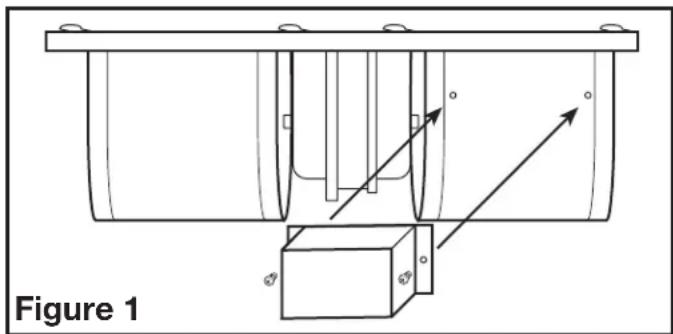
- Attach the capacitor to the blower by lining up the two holes on the flange of the capacitor with the holes on the blower. Use the 2 included #6 screws to make the connection and fully tighten (Figure 1).
natural_image
Technical line drawing of a mechanical assembly with arrows indicating motion or force direction (no text or symbols)- The installation of the blower is slightly different from one canopy height to another. For 18" high canopies proceed to Section 2, for 10" high canopies proceed to Section 3.
SECTION 2
Installation into 18" High Canopy
- Install transformer into hood canopy by lining up the 2 holes on the flange of the transformer with the 2 screw studs in the top left side of the hood canopy. Use 2 of the included #8-32 screws to make the connection and fully tighten (Figure 2).
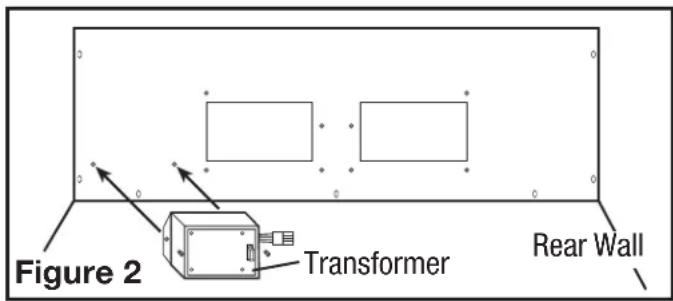
text_image
Figure 2 Transformer Rear Wall- Loosely install the two #10-32 serrated flange nuts (included) onto the studs located inside the top center of the hood.
- Lift blower up into the hood canopy and slide the keyhole slots in the blower mounting flange over the two studs of the hood. Slide the blower into place and tighten the hex nuts on the mounting stud while lining up the 8 holes in the blower mounting flange to the 8 screw studs of the hood (Figure 3).
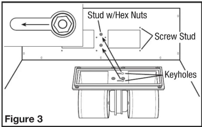
text_image
Stud w/Hex Nuts Screw Stud Keyholes Figure 3- Using 8 of the included #8-32 screws, flat washers and star washers, mount the blower in place and tighten all screws. Confirm that the blower is securely seated in place and there are no air gaps around the blower gasket.
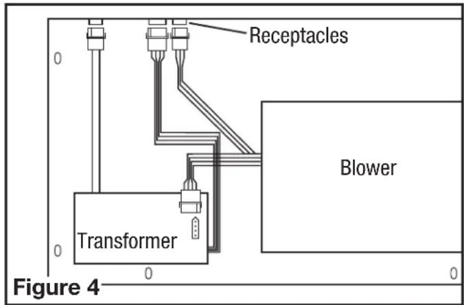
- Plug the 3 wire quick connect cord from the blower into the receptacle on the range hood canopy. Plug the 4 wire quick connect cord from the blower into the receptacle on the transformer. Plug the 2 wire quick connect from the transformer into the receptacle on the range hood canopy. Plug the 4 wire quick connect from the transformer into the receptacle on the range hood canopy. These cords will only fit into the receptacles one way (Figure 4).
text_image
Receptacles Blower Transformer Figure 4SECTION 3
Installation into 10" High Canopy
- Remove the rear bottom plate of the hood canopy. It is secured in place with a nut and washer on either side (Figure 5).
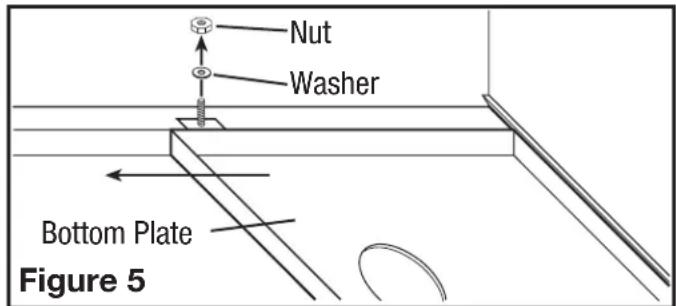
text_image
Nut Washer Bottom Plate Figure 5- Install transformer into hood canopy by lining up the 2 holes on the flange of the transformer with the 2 screw studs in the top left side of the hood canopy. Use 2 of the included #8-32 screws to make the connection and fully tighten (Figure 2).
- Loosely install the two #10-32 serrated flange nuts (included) onto the studs located inside the top center of the hood.
- Lift blower up into the hood canopy and slide the keyhole slots in the blower mounting flange over the two studs of the hood. Slide the blower into place and tighten the hex nuts on the mounting stud while lining up the 8 holes in the blower mounting flange to the 8 screw studs of the hood (Figure 3).
- Using 8 of the included #8-32 screws, flat washers and star washers, mount the blower in place and tighten all screws. Confirm that the blower is securely seated in place and there are no air gaps around the blower gasket.
- Plug the 3 wire quick connect cord from the blower into the receptacle on the range hood canopy. Plug the 4 wire quick connect cord from the blower into the receptacle on the transformer. Plug the 4 wire quick connect from the transformer into the receptacle on the range hood canopy. These cords will only fit into the receptacles one way (Figure 4).
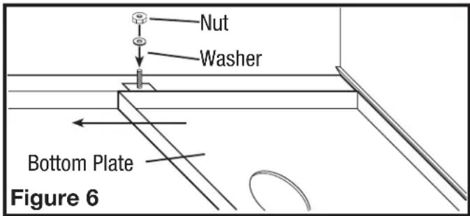
- Reinstall the rear bottom plate by fitting the back edge of the plate into the channel located on the back of the hood and reinstalling the two nuts and washers removed in Step 1 (Figure 6).
text_image
Nut Washer Bottom Plate Figure 6SECTION 4
Finishing the Installation
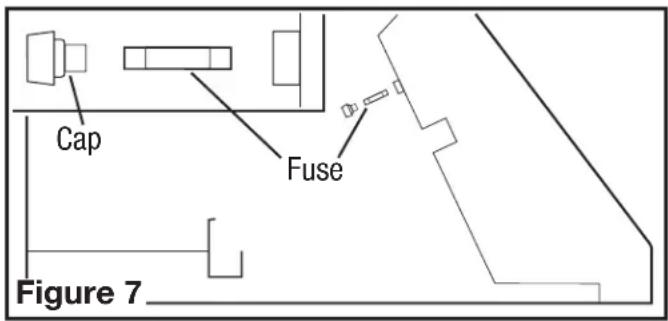
- Install the included fuse into the electrical panel by turning the fuse cap counter clockwise and pulling out. Insert the included 1/4" x 1-1/4" time delay fuse in the holder and reinstall into the panel (Figure 7).
text_image
Cap Fuse Figure 7NOTE: If you need to replace the fuse, replace with a 1/4" x 1-1/4" Bussman MDA-10 or equivalent 10 amp, 250V ceramic, time delay fuse only.
- Refer to the hood instruction manual to complete the installation, for maintenance, and before restoring power.
- The blower is covered under the range hood's warranty.
REPLACEMENT PARTS DIAGRAM
natural_image
Technical line drawing of a mechanical device with labeled components (no text or symbols)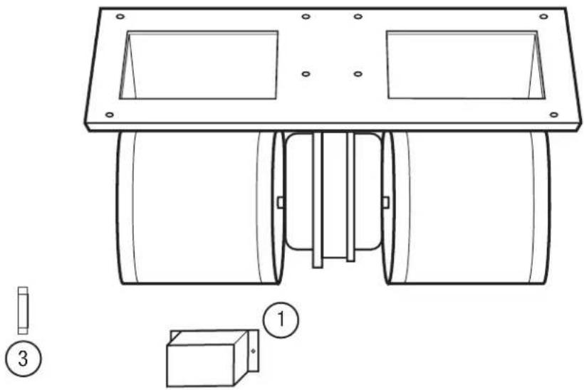
natural_image
Technical line drawing of a mechanical component with mounting holes and internal channels (no text or symbols)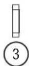
| # Qy. Description Replacement Part # | ||
| 1 1 | Capacitor Box 5S1136114 | |
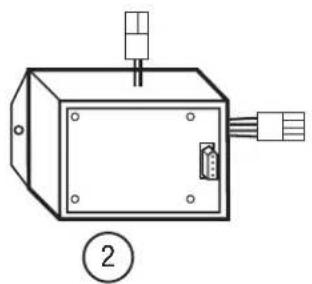
| 2 1 | Transformer (B900) 5S1136513 | |
| 1 Transformer (B1125) 5S1136512 | ||
| 3 1 | Fuse 5S1136131 | |
INSTRUCTIONS IMPORTANTES - MODE D'EMPLOI
natural_image
Technical line drawing of a mechanical assembly with arrows indicating motion or force direction (no text or symbols)natural_image
Technical line drawing of a mechanical device with labeled components (no text or symbols)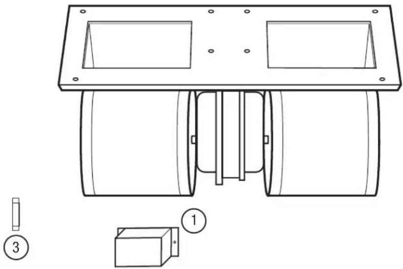
natural_image
Technical line drawing of a mechanical component with mounting holes and internal channels (no text or symbols)