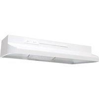
AV1365 - Range hood Air King - Free user manual and instructions
Find the device manual for free AV1365 Air King in PDF.


| Product Type | Range Hood |
| Brand | Air King |
| Model | AV1365 |
| Dimensions (L x D x H) | 76.2 x 50 x 15 cm (approximate) |
| Weight | Approximately 5 kg |
| Power Supply | 120 V, 60 Hz, AC |
| Motor Power | Not specified |
| Airflow | Not specified |
| Duct Type | 8.25 x 25.4 cm (3-1/4 x 10 in) rectangular or 17.78 cm (7 in) round |
| Main Functions | Exhaust or recirculation (with optional charcoal filter), 2-speed fan, lighting |
| Controls | Rocker switches for lighting (ON/OFF) and fan (High/Low/Off) |
| Lighting | A19 bulb, max 60 W (not included) |
| Grease filter | Aluminum, washable monthly (model RF35) |
| Charcoal filter (optional) | Model RF34 or RF55, not washable, replace annually |
| Installation | Under cabinet, wall or ceiling, metal duct required |
| Care and cleaning | Washable filter, surface with mild detergent, vacuum on fan |
| Safety | Grounding, cut power before maintenance, do not use with electronic speed control |
| Spare parts and repairability | Parts list available: filters, motor, switches, lens, etc. (see manual) |
| Warranty | 1 year parts and labor, 5 years motor |
| General information | Residential use, general ventilation only |
Frequently Asked Questions - AV1365 Air King
User questions about AV1365 Air King
0 question about this device. Answer the ones you know or ask your own.
Ask a new question about this device
Download the instructions for your Range hood in PDF format for free! Find your manual AV1365 - Air King and take your electronic device back in hand. On this page are published all the documents necessary for the use of your device. AV1365 by Air King.
USER MANUAL AV1365 Air King
IMPORTANT INSTRUCTIONS - OPERATING MANUAL
AV Series
AirKing Ventilation Products®
Range Hood
READ AND SAVE THESE INSTRUCTIONS
READ CAREFULLY BEFORE ATTEMPTING TO ASSEMBLE, INSTALL, OPERATE OR MAINTAIN THE PRODUCT DESCRIBED. PROTECT
YOURSELF AND OTHERS BY OBSERVING ALL SAFETY INFORMATION. FAILURE TO COMPLY WITH
INSTRUCTIONS COULD RESULT IN PERSONAL INJURY AND/OR PROPERTY DAMAGE!
RETAIN INSTRUCTIONS FOR FUTURE REFERENCE.
GENERAL SAFETY INFORMATION
When using electrical appliances, basic precautions
should always be followed to reduce the risk of fire,
electric shock and injury to person, including the following:
WARNING: TO REDUCE THE RISK OF FIRE, ELECTRIC SHOCK AND INJURY TO PERSON, OBSERVE THE FOLLOWING:
- Read all instructions before installing or using range hood.
- Use this unit only in the manner intended by the manufacturer. If you have questions, contact the manufacturer.
- Before servicing or cleaning the unit, switch power off at service panel and lock the service disconnecting means to prevent power from being switched on accidentally. When the service disconnecting means cannot be locked, securely fasten a prominent warning device, such as a tag, to the service panel.
- Installation work and electrical wiring must be done by qualified person(s) in accordance with all applicable codes and standards, including fire-related construction.
- Sufficient air is needed for proper combustion and exhausting of gases through the flue (chimney) of fuel burning equipment to prevent back drafting. Follow the heating equipment manufacturer's guideline and safety standards such as those published by the National Fire Protection Association (NFPA) and the American Society for Heating, Refrigeration, and Air Conditioning Engineers (ASHRAE), and the local code authorities.
CAUTION: FOR GENERAL VENTILATING USE ONLY. DO NOT USE TO EXHAUST HAZARDOUS OR EXPLOSIVE MATERIALS AND VAPORS.
- When cutting or drilling into wall or ceiling, do not damage electrical wiring and other hidden utilities.
CAUTION: TO REDUCE THE RISK OF FIRE AND TO PROPERLY EXHAUST AIR, BE SURE TO DUCT AIR OUTSIDE - DO NOT VENT EXHAUST AIR INTO SPACES WITHIN WALLS OR CEILINGS OR INTO ATTICS, CRAWL SPACES, OR GARAGES.
- This unit must be grounded.
- To avoid motor bearing damage and noisy and/or unbalanced impellers, keep drywall spray, construction dust, etc. off power unit.
WARNING: TO REDUCE THE RISK OF FIRE, ELECTRIC SHOCK, DO NOT USE THIS FAN WITH ANY SOLID-STATE SPEED CONTROL DEVICE.
WARNING: TO REDUCE THE RISK OF A RANGE TOP GREASE FIRE:
a) Never leave surface units unattended at high settings. Boilovers cause smoking and greasy spillovers that may ignite. Heat oils slowly on low or medium settings.
b) Always turn hood ON when cooking at high heat or when flambéing food (ie. Crepes Suzette, Cherries Jubilee, Peppercorn Beef Flambé).
c) Clean ventilating fans frequently. Grease should not be allowed to accumulate on fan filter.
d) Use proper pan size. Always use cookware appropriate for the size of the surface element.
WARNING: TO REDUCE THE RISK OF INJURY TO PERSONS IN THE EVENT OF A RANGE TOP GREASE FIRE, OBSERVE THE FOLLOWING:
a) SMOTHER FLAMES with a close-fitting lid, cookie sheet, or metal tray, then turn off burner. BE CAREFUL TO PREVENT BURNS. If the flames do not go out immediately, EVACUATE AND CALL THE FIRE DEPARTMENT.
b) NEVER PICK UP A FLAMING PAN - You may be burned.
c) DO NOT USE WATER, including wet dishcloths or towels - a violent steam explosion will result.
d) Use an extinguisher ONLY if:
I. You know you have a Class ABC extinguisher, and you already know how to operate it.
II. The fire is small and contained in the area where it started.
III. The fire department is being called.
IV. You can fight the fire with your back to an exit.
WARNING: TO REDUCE THE RISK OF FIRE, USE ONLY METAL DUCTWORK.
SAVE THESE INSTRUCTIONS
INSTALLATION INSTRUCTIONS
- Unpack hood from the carton and confirm that all pieces are present. In addition to the range hood you should have:
1 - Aluminum Grease Filter
1 - 3-1/4"x 10" Damper
3 - Damper Mounting Screws
4 - #8 Mounting Screws
1 - Instruction/Safety Sheet
-
Lay the hood flat on a table so the underside is facing you. Use a piece of cardboard to avoid damaging the table or the hood.
-
Remove wire compartment cover screw and then lamp cover by squeezing the two tabs together (Figure 1).
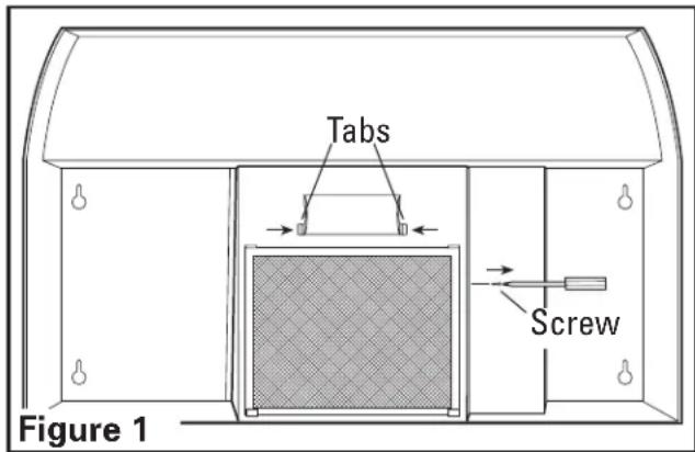
- Install a 60 watt maximum type A19 bulb and reinstall the lamp cover.
Prepare the location for Hood Support
- If the hood will be installed under cabinets that have a recessed bottom, it will be necessary to install wood mounting strips (not included) so the hood will mount properly (Figure 2).
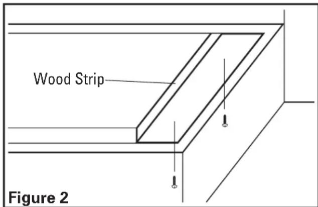
- The thickness of the strips should be the same as the recess of the cabinet and they should be approximately 2" wide.
- Install the strips using appropriate length wood screws (not included). Make sure the strips line up to the keyhole slots of the range hood.
Prepare the Hood for Installation
- Choose the type of ducting you will require. This model is equipped to vent either Vertically or Horizontally through a 3-1/4" x 10" duct. It can be modified to be ductless (re-circulates the air back into the kitchen) with the addition of a model RF34 Charcoal Filter (not
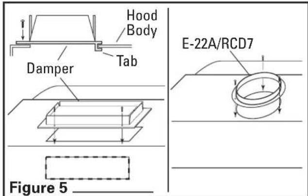
included) or vented through a 7" round duct with the addition of a model E-22a or RDC7 Duct Collar (not included) (Figure 3).

2a. Horizontal or Vertical - Remove the square knockout by inserting a screw driver under the edge and break the tabs holding it in place. Peel back with pliers (Figure 4).
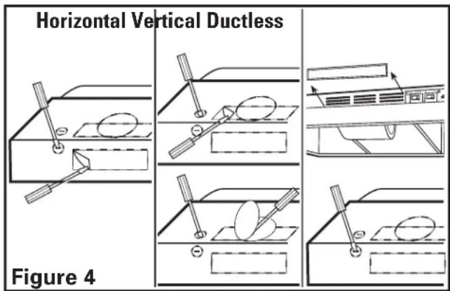
2b. Ductless - Remove the hood's front louver cover, exposing the front air slots. To remove louver slide to one side and lift the trailing edge. Do not use a screwdriver or any other object that could scratch the hood (Figure 4).
2c. 7" Round - Remove the round knockout located on the top of the hood by inserting a screw driver under the edge and break the tabs holding it in place. Peel back with pliers (Figure 4).
3. Determine where the electrical service will enter the hood and remove the appropriate electrical knockout by inserting a screw driver into the slot and rocking back and forth until the knockout comes loose (Figure 4).
CAUTION: MAKE SURE POWER IS SWITCHED OFF AT SERVICE PANEL BEFORE STARTING INSTALLATION.
Installing the Range Hood
- Once the proper knockout(s) have been removed, either hold the hood up to the installation location and mark the locations of the ducting, electrical, and mounting holes or mark the locations by measurement.
- Cut appropriate holes for ducting connection and electrical connection in the wall/cabinet.
- For 3-1/4" x 10" vertical or horizontal ducting, install the damper assembly to the hood by sliding the tabbed section of the damper under the hood body and securing with the two provided screws. For 7" round ducting, secure either a model E-22A or RCD7 Duct Collar (not included) to the hood with the three provided screws (Figure 5).
- Install an approved wire connector to the electrical knockout of the hood and guide the electrical cable through the hood, allowing at least 6" of wire for connections and tighten.
NOTE: If installing into existing construction and you will not have access to the ductwork once the hood is in place, make ducting connections at this point. Refer to the Ducting Section for instructions.
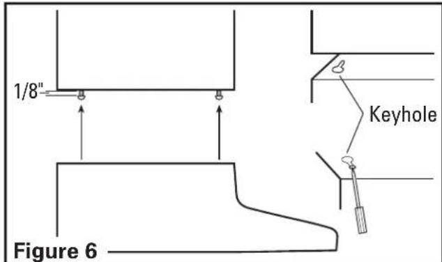
- Install the 4 mounting screw at the previously marked locations. Leave approximately 1/8" clearance. Slide the hood in place through the keyhole slots and align the front of the hood so that it is flush with the front of the cabinets. Tighten all screws securely (Figure 6).
Wiring
CAUTION: ALL ELECTRICAL CONNECTIONS MUST BE MADE IN ACCORDANCE WITH LOCAL CODES, ORDINANCES, OR NATIONAL ELECTRICAL CODE. IF YOU ARE UNFAMILIAR WITH METHODS OF INSTALLING ELECTRICAL WIRING, SECURE THE SERVICES OF A QUALIFIED ELECTRICIAN.
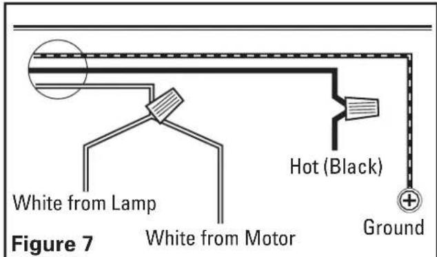
- Connect the 2 loose White wires from the range hood to the White wire from the supply, and the loose Black wire from the range hood to the Black wire of the supply. Connect the ground wire (green or bare) from the supply to the green ground screw of the hood. Use approved methods for all connections (Figure 7).
NOTE: DO NOT disconnect any wiring that has already been crimped with a wire connector from the factory.
- Replace the wire compartment cover and tighten screw. Make sure all wiring is securely contained within the wire compartment.
Ducting
CAUTION: ALL DUCTING MUST COMPLY WITH LOCAL AND NATIONAL BUILDING CODES.
WARNING: TO REDUCE THE RISK OF FIRE, USE ONLY METAL DUCTWORK.
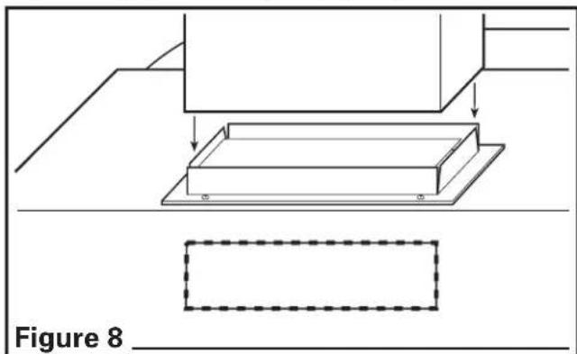
- Connect the ducting to the hood's duct collar and damper. Secure in place using tape to seal all joints (Figure 8).
CAUTION: ALWAYS DUCT THE FAN TO THE OUTSIDE THROUGH A WALL OR ROOF CAP.
Finishing the Installation
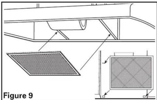
- Install the appropriate filters, sliding the back side of the filter into the tab and pressing the front of the filter into place (Figure 9).
- Turn switches to the "OFF" position and restore power. Test that the light and the fan are operating properly.
- If there is any vibration noise, check for the source and try to tighten fasteners or adjust the tape to make a tighter connection or seal.
Operation
Controls
Your Range Hood is equipped with two rocker style switches with one controlling the lighting and the other controlling the exhaust fan. The light switch has two positions, ON (●) and OFF (○). The fan is a three position switch, HIGH (●●), LOW (●), and OFF. OFF is the middle position of the switch.
Maintenance
CAUTION: MAKE SURE POWER IS SWITCHED OFF AT SERVICE PANEL BEFORE SERVICING THE UNIT.
Filters
- Grease Filter - Included with your range hood is an aluminum grease filter that should be washed in hot water with detergent
once a month. Reverse the instructions in the "Finishing the Installation" section of the instructions to remove filter. If the grease filter becomes damaged, replace with Air King Model RF35 Grease Filter.
- Charcoal Odor Filter - If you have installed an optional charcoal odor filter or a combination grease/charcoal filter, they cannot be washed and must be discarded and replaced when they become noticeably dirty, have stopped filtering the odors, or at least once per year. Replace with Air King Model RF34 Odor Filter or Model RF55 Combination Odor/Grease Filter.
Cleaning
CAUTION: DO NOT USE GASOLINE, BENZINE, THINNER, HARSH CLEANSERS, ETC., AS THEY MAY DAMAGE THE RANGE HOOD.
- Clean your range hood with a mild detergent, such as dishwashing liquid, and dry with a soft cloth. NEVER USE ANY ABRASIVE PADS OR SCOURING POWDERS. Completely dry before restoring power. NEVER IMMERSE ELECTRICAL PARTS IN WATER.
- The fan assembly can be vacuumed when build up (dirt, lint, etc.) accumulates over time. The fan is permanently lubricated and does not require oiling.
Troubleshooting Guide
| Trouble Probable Cause Suggested Remedy | ||
| 1. Hood does not operate when the switch is on. | 1a. A fuse may be blown or a circuit tripped.1b. Wiring is not connected properly. 1b. Turn off power to unit. Check that all wires are connected | 1a. Replace fuse or reset circuit breaker. |
| 2. Hood is operating, but air moves slower than normal. | 2. Obstruction in the exhaust ducting. | 2. Check for any obstructions in the ducting including filter. |
| 3. Hood is making a rattling noise. | 3a. Motor is loose.3b. Duct connection is loose. 3b. Turn off power to unit. Check that duct connection is tight. | 3a. Turn off power to unit. Remove filter, check that all screws are fully tightened. |
LIMITED WARRANTY
All products manufactured by Air King Limited are warranted for one year from the date of purchase against defects in workmanship and/or material. In addition, all ventilating/exhaust fans, heaters, combination fan lights and/or heaters, and range hoods are guaranteed for five years from the date of purchase against defects in workmanship and/or material.
This warranty does not cover any labor or shipping costs or the cost of replacement components as part of routine maintenance such as: range hood grease filters, charcoal filters or combination charcoal/grease filters; replacement light bulbs in range hoods or bathroom fan/light/bulb heater combinations. As well, any damage or failure caused by abuse, misuse, abnormal usage, faulty installation, or improper maintenance will not be covered by this warranty.
In order to make a claim on this warranty, you must be the original consumer of the product. You will be required to present to Air King the original bill of sale showing: date of purchase, place of purchase and model purchased. Failure to meet these requirements will void your warranty.
Air King will not be held responsible for any bodily injury or damages to personal property or real estate whether caused directly or indirectly by the product. Some states and provinces do not allow the exclusion or limitation of incidental or consequential damages and some states do not allow limitations on how long an implied warranty lasts, so these exclusions or limitations may not apply to you. This warranty gives you specific legal rights and you may have other rights which vary from state to state and province to province.
FOR PARTS OR TECHNICAL ASSISTANCE
Please call: 1-800-465-7300, MONDAY THROUGH FRIDAY, BETWEEN THE HOURS OF 8 AM AND 4:00 PM EST. PLEASE DO NOT RETURN PRODUCT TO PLACE OF PURCHASE.
Reference the type and style of product (located on label inside of the product) when you call. For more information please visit our website: wwwairkinglimited.com
REPLACEMENT PARTS DIAGRAM
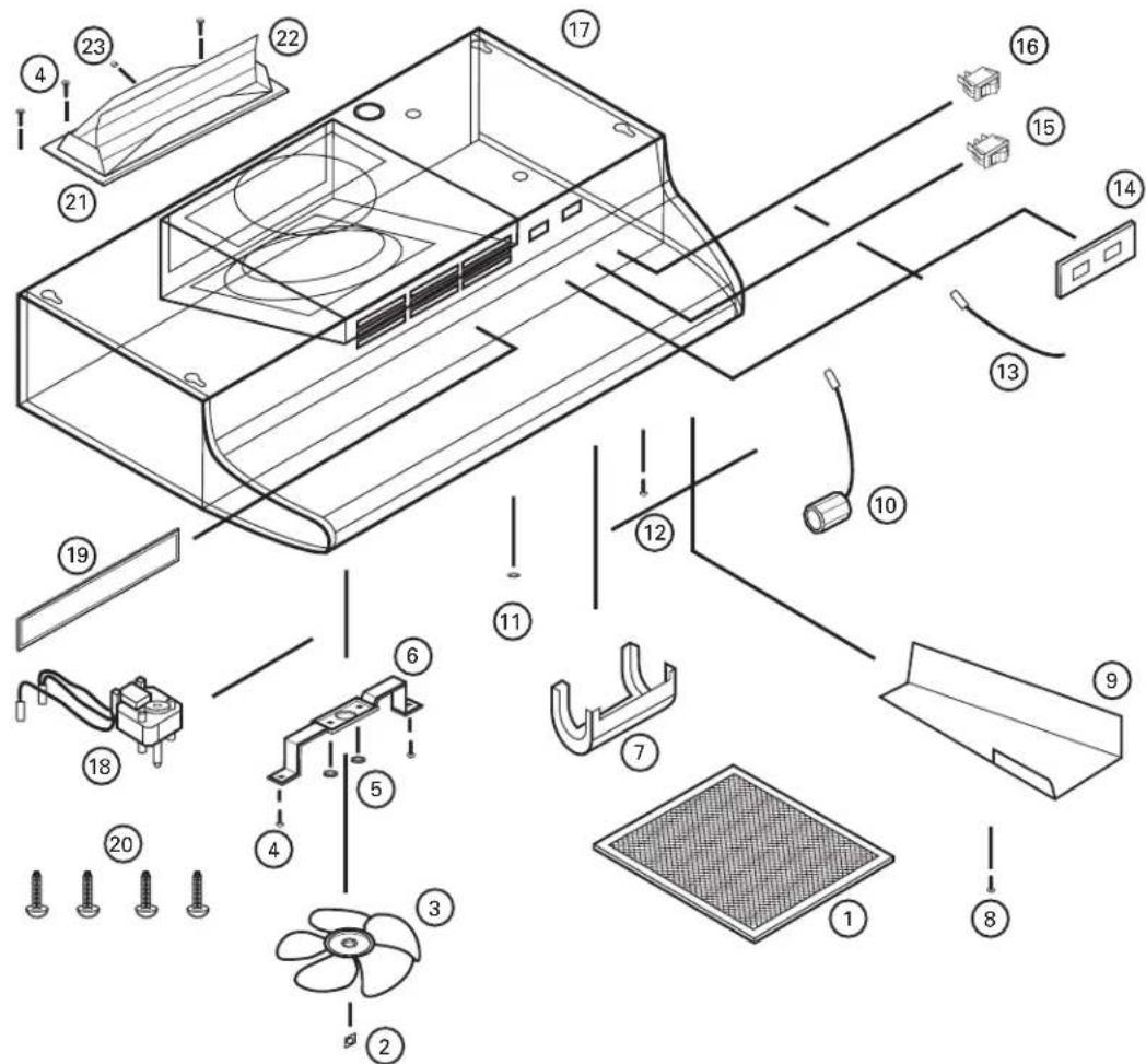
| # Description Replacement Part # | ||
| 1 Filter RF35 | 5S4199011 | |
| 2 Push Nut 5S4199001 | ||
| 3 Fan Blade | 5S4199002 | |
| 4 #8 B Screw | 5S1999015 | |
| 5 Hex Nut | 5S1999006 | |
| 6 Motor Bracket | 5S4199003 | |
| 7 Light Lens 5S4199004 | ||
| 8 #6 AB Screw | 5S1999004 | |
| 9 Wire Compartment Cover | 5S4199005 | |
| 10 Lamp Holder | 5S4199006 | |
| 11 Bushing | 5S1999016 | |
| 12 #10 Ground Screw | 5S1999002 | |
| 13 Jumper Wire | 5S4199007 | |
| 14 Switch Plate - White | 5S1421003 | |
| Biscuit 5S1421004 | ||
| Almond 5S1421005 | ||
| Black 5S1421006 | ||
| 15 Motor Switch - White | 5S1418003 | |
| Biscuit 5S1418004 | ||
| Almond 5S1418005 | ||
| Black 5S1418006 | ||
| # Description Replacement Part # | ||
| 16 Light Switch - White 5S1419003 | ||
Installer:
Installation Date:
Place of Purchase:
Model Number:
INSTRUCTIONS IMPORTANTES - MANUEL D'OPÉRATION
Séries AV

Hotte de Cuisine
LIRE ET CONSERVER CES INSTRUCTIONS
LIRE SOIGNEUSEMENT AVANT DE TENTER D'ASSEMBLER, INSTALLER, OPÉRER OU DE RÉPARER LE PRODUIT DÉCRIT. PROTÉGEZ VOUS-MÊME ET LES AUTRES EN OBSERVANT TOUTE L'INFORMATION DE SÉCURITÉ. FAILIR À SE CONFORMER AUX INSTRUCTIONS PEUT RÉSULTER EN BLESSURE PERSONNELLE GRAVE ET/OU EN DOMMAGE À LA PROPRIETÉ.
CONSERVER CES INSTRUCTIONS POUR RÉFÉRENCES FUTURES.
INSTRUCTIONS GÉNÉRALES DE SÉCURITÉ
natural_image
Technical diagram showing a mechanical assembly with a rectangular component and a dashed outline, labeled Figure 8 (no text or symbols on the diagram itself)AVERTISSEMENT: TOUJOURS PASSER LES CONDUITS DU VENTILATEUR VERS L'EXTÉRIEUR EN UTILISANT UN CAPUCHON MURAL OU DE TOIT.
| # Descripción Número de Repuesto | ||
| 1 Filtro RF35 | 5S4199011 | |
| 2 | Tuercas A Presión | 5S4199001 |
| 3 | Aspa del Ventilador | 5S4199002 |
| 4 | Tornillo #8 B | 5S1999015 |
| 5 | Tuerca Hexagonal | 5S1999006 |
| 6 | Ménsula del Motor | 5S4199003 |
| 7 | Lentes de la Luz | 5S4199004 |
| 8 | Tornillo #6 AB | 5S1999004 |
| 9 | Cubierta del Compartimiento de Cable | 5S4199005 |
| 10 | Soporte de la Lámpara | 5S4199006 |
| 11 | Buje | 5S1999016 |
| 12 | Tornillo a Tierra #10 | 5S1999002 |
| 13 | Cable de Arranque | 5S4199007 |
| 14 | Placa del Interruptor - Blanco | 5S1421003 |
| Bizcocho 5S1421004 | ||
| Almendra 5S1421005 | ||
| Negro 5S1421006 | ||
| 15 | Interruptor del Motor - Blanco | 5S1418003 |
| Bizcocho 5S1418004 | ||
| Almendra 5S1418005 | ||
| Negro 5S1418006 | ||
| # Descripción Número de Repuesto | ||
| 16 Interruptor de la Luz - Blanco 5S1419003 | ||
| Bizcocho 5S1419004 | ||
| Almendra 5S1419005 | ||
| Negro 5S1419006 | ||
| 17 | Envoltorio - 21" 5S1427010 | |
| 24" 5S1427020 | ||
| 30" 5S1427030 | ||
| 36" 5S1427040 | ||
| 42" 5S1427050 | ||
| 18 | Motor 5S2199001 | |
| 19 | Placa de la Parrilla - Blanco 5S1429003 | |
| Bizcocho 5S1429004 | ||
| Almendra 5S1429005 | ||
| Negro 5S1429006 | ||
| 20 | Tornillo #8 5S1999017 | |
| 21 | Montura del Regulador de Tiro 5S4199013 | |
| 22 | Regulador de Tiro 5S4199014 | |
| 23 | Amortiguador del Regulador de Tiro 5S4199015 | |
Instalador:

- IMPORTANT INSTRUCTIONS - OPERATING MANUAL
- READ AND SAVE THESE INSTRUCTIONS
- GENERAL SAFETY INFORMATION
- WARNING: TO REDUCE THE RISK OF FIRE, ELECTRIC SHOCK AND INJURY TO PERSON, OBSERVE THE FOLLOWING:
- CAUTION: FOR GENERAL VENTILATING USE ONLY. DO NOT USE TO EXHAUST HAZARDOUS OR EXPLOSIVE MATERIALS AND VAPORS.
- CAUTION: TO REDUCE THE RISK OF FIRE AND TO PROPERLY EXHAUST AIR, BE SURE TO DUCT AIR OUTSIDE - DO NOT VENT EXHAUST AIR INTO SPACES WITHIN WALLS OR CEILINGS OR INTO ATTICS, CRAWL SPACES, OR GARAGES.
- WARNING: TO REDUCE THE RISK OF FIRE, ELECTRIC SHOCK, DO NOT USE THIS FAN WITH ANY SOLID-STATE SPEED CONTROL DEVICE.
- WARNING: TO REDUCE THE RISK OF A RANGE TOP GREASE FIRE:
- WARNING: TO REDUCE THE RISK OF INJURY TO PERSONS IN THE EVENT OF A RANGE TOP GREASE FIRE, OBSERVE THE FOLLOWING:
- WARNING: TO REDUCE THE RISK OF FIRE, USE ONLY METAL DUCTWORK.
- SAVE THESE INSTRUCTIONS
- INSTALLATION INSTRUCTIONS
- Prepare the location for Hood Support
- Prepare the Hood for Installation
- CAUTION: MAKE SURE POWER IS SWITCHED OFF AT SERVICE PANEL BEFORE STARTING INSTALLATION.
- Installing the Range Hood
- Wiring
- Ducting
- Finishing the Installation
- Operation
- Controls
- Maintenance
- CAUTION: MAKE SURE POWER IS SWITCHED OFF AT SERVICE PANEL BEFORE SERVICING THE UNIT.
- Filters
- Cleaning
- CAUTION: DO NOT USE GASOLINE, BENZINE, THINNER, HARSH CLEANSERS, ETC., AS THEY MAY DAMAGE THE RANGE HOOD.
- LIMITED WARRANTY
- FOR PARTS OR TECHNICAL ASSISTANCE
- INSTRUCTIONS IMPORTANTES - MANUEL D'OPÉRATION
- LIRE ET CONSERVER CES INSTRUCTIONS
- CONSERVER CES INSTRUCTIONS POUR RÉFÉRENCES FUTURES.
- INSTRUCTIONS GÉNÉRALES DE SÉCURITÉ
Brand : Air King
Model : AV1365
Category : Range hood