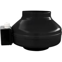
IL12 - Range hood Air King - Free user manual and instructions
Find the device manual for free IL12 Air King in PDF.


| Product Type | Exhaust Fan |
| Brand | Air King |
| Model | IL12 |
| Power Supply | 120 V, 60 Hz |
| Intended Use | General ventilation only, do not use in kitchens |
| Installation | Wall or ceiling, with duct to the outside |
| Housing Material | Steel (not specified, estimate) |
| Weight | Approximately 2.5 kg (estimate) |
| Dimensions (L × W × H) | Approximately 30 × 30 × 20 cm (estimate) |
| Motor Type | Capacitor motor, sealed bearings |
| Airflow | Not specified (varies with installation) |
| Sound Level | Varies with installation, use of insulated flexible duct recommended |
| Compatible Controls | Wall switch, electronic speed control |
| Electrical Protection | GFCI recommended if installed above a bathtub or shower |
| Maintenance | Clean the grille with a mild detergent, dry before reassembly. Do not use abrasive pads. |
| Lubrication | None required (sealed bearings) |
| Warranty | 5 years for the original purchaser |
| Customer Service | Toll-free: 1-800-465-7300 (Mon-Fri 8am-4pm EST) |
| Spare Parts | Motor, grille, mounting brackets, inlet housing (availability varies) |
| Repairability | Repair by a qualified professional recommended. Some components not available to consumers. |
Frequently Asked Questions - IL12 Air King
User questions about IL12 Air King
0 question about this device. Answer the ones you know or ask your own.
Ask a new question about this device
Download the instructions for your Range hood in PDF format for free! Find your manual IL12 - Air King and take your electronic device back in hand. On this page are published all the documents necessary for the use of your device. IL12 by Air King.
USER MANUAL IL12 Air King
IMPORTANT INSTRUCTIONS - OPERATING MANUAL
IL Series

In-Line Exhaust Fan
READ AND SAVE THESE INSTRUCTIONS
READ CAREFULLY BEFORE ATTEMPTING TO ASSEMBLE, INSTALL, OPERATE OR MAINTAIN THE PRODUCT DESCRIBED. PROTECT YOURSELF AND OTHERS BY OBSERVING ALL SAFETY INFORMATION. FAILURE TO COMPLY WITH INSTRUCTIONS COULD RESULT IN PERSONAL INJURY AND/OR PROPERTY DAMAGE!
RETAIN INSTRUCTIONS FOR FUTURE REFERENCE.
GENERAL SAFETY INFORMATION
When using electrical appliances, basic precautions should always be followed to reduce the risk of fire, electric shock and injury to person, including the following:
WARNING: TO REDUCE THE RISK OF FIRE, ELECTRIC SHOCK AND INJURY TO PERSON, OBSERVE THE FOLLOWING:
a) Use this unit only in the manner intended by the manufacturer. If you have questions, contact the manufacturer.
b) Before servicing or cleaning the unit, switch power off at service panel and lock the service disconnecting means to prevent power from being switched on accidentally. When the service disconnecting means cannot be locked, securely fasten a prominent warning device, such as a tag, to the service panel.
WARNING: TO REDUCE THE RISK OF FIRE, ELECTRIC SHOCK AND INJURY TO PERSON, OBSERVE THE FOLLOWING:
a) Installation work and electrical wiring must be done by qualified person(s) in accordance with all applicable codes and standards, including fire-related construction.
b) Sufficient air is needed for proper combustion and exhausting of gases through the flue (chimney) of fuel burning equipment to prevent back drafting. Follow the heating equipment manufacturer's guideline and safety standards such as those published by the National Fire Protection Association (NFPA) and the American Society for Heating, Refrigeration, and Air Conditioning Engineers (ASHRAE), and the local code authorities.
c) When cutting or drilling into wall or ceiling, do not damage electrical wiring and other hidden utilities.
d) Ducted fans must always be vented to the outdoors.
e) If this unit is to be installed over a tub or shower, it must be marked as appropriate for the application and be connected to a GFCI (Ground Fault Circuit Interrupter) - protected branch circuit.
f) This unit must be grounded.
g) To avoid motor bearing damage and noisy and/or unbalanced impellers, keep drywall spray, construction dust, etc. off power unit.
h) Suitable for use with electronic speed control device.
i) Do not install into ceilings thermally insulated to a value greater than R40.
CAUTION: FOR GENERAL VENTILATING USE ONLY. DO NOT USE TO EXHAUST HAZARDOUS OR EXPLOSIVE MATERIALS AND VAPORS.
WARNING: DO NOT USE IN KITCHENS.
k) Read all instructions before installing or using exhaust fan.
INSTALLATION INSTRUCTIONS
CAUTION: MAKE SURE POWER IS SWITCHED OFF AT SERVICE PANEL BEFORE STARTING INSTALLATION.
SECTION 1
Preparing the Exhaust Fan
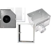
- Unpack fan from the carton and confirm that all pieces are present. In addition to the exhaust fan you should have:
POWER UNITS KITS
1 - Blower 1 - Blower
1 - Mounting Bracket 1 - Mounting Bracket
1 - Instruction/Safety Sheet 1 or 2 - Room Inlet with Grill
1 - Instruction/Safety Sheet
- When selecting fan mounting location, the following criteria should be considered:
a) Mounting to minimize noise generated by fan operation: Mounting the fan as far as possible from the intake point will minimize fan operating noise from being transmitted back through the duct work. If the fan is to be used as a booster for moving the air between two rooms, a central point along the duct may be optimal. Insulated flexible type duct work (recommended for all bathroom exhaust applications) will result in much quieter operation. It is recommended that a minimum 8' of insulated flexible ducting be used between any exhaust grill and fan for low noise level.
b) Service accessibility: Fan location should allow sufficient access for service.
SECTION 2
Installing the Fan
- Attach the included mounting bracket to the wall stud or ceiling joist. Connect the fan to the mounting bracket using the included screws (Figure 1).
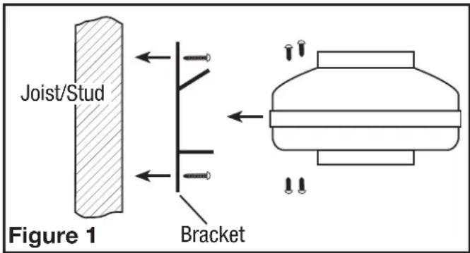
NOTE: Fan mounting can be at any point along the duct and in any angle, however, vertical mounting is recommended to reduce condensation buildup in the fan. If a horizontal installation is necessary and condensation buildup may pose a problem, wrap insulation around the fan to minimize buildup.
SECTION 3
Room Inlets (Included with Kits Only)
New Construction
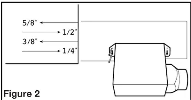
- Using the gauge on the fan's housing (Figure 2), line up housing so that it will be flush with the finished ceiling or wall. Position the fan so that the tabs rest flat against the joist or stud and secure with four nails (not provided) to ensure proper installation.
Existing Construction
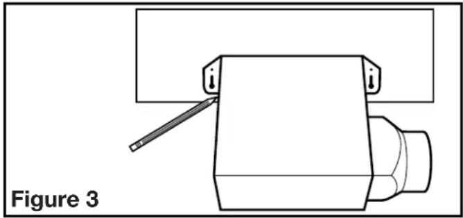
- Position housing against the joist or stud and trace an outline of the housing onto the ceiling/wall material (Figure 3). Set housing aside and cut opening, being careful not to cut or damage any electrical or other hidden utilities. Place housing next to the joist or stud and insure that it is flush with the finished ceiling. Secure with four nails (not provided) to ensure proper installation (Figure 2).
SECTION 4
Ducting
CAUTION: ALL DUCTING MUST COMPLY WITH LOCAL AND NATIONAL BUILDING CODES.
NOTE: Insulated ducting is required for bathroom exhaust applications, where ducting passes through unconditioned space or where noise is a factor. Failure to use insulation could result in excessive condensation buildup within the duct, and undesirable sound levels within the room. Duct runs should have as few bends as possible.
NOTE: Flexible insulated ducting may be used where allowed by local code. For the quietest possible installations, it is recommended a minimum of 8' of insulated flexduct be used between any exhaust grill and fan. When using flexible type duct work, duct should be stretched as tight and straight as possible. Failure to do so could result in dramatic loss of system performance. Flexible duct should be connected to the fan with screw clamps or duct tape. All connections should be as airtight as possible to maximize system performance.
- Connect one end of the ducting (not included) to the room level collar/damper and the other end to the "Y" transition. Secure both ends in place using tape or a screw clamp to create as air tight a seal as possible. Repeat this step for the other room level grill housing (Figure 4).
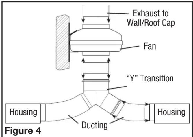
NOTE: Units that include only one collar do not utilize the "Y" transition. Follow the same instructions as in step 1, except connect the one end of the ducting directly to the fan.
- Connect one end of the ducting to the top of the "Y" transition and the other end to the intake of the fan (Figure 4).
- Connect one end of the ducting to the exhaust of the fan and the other end to a wall or ceiling cap (Figure 4). Always duct the fan to the outside through a wall or roof cap.
NOTE: When using insulated flex duct, it is recommended that the inner vinyl core be screw clamped or taped to the inlet and outlet and that the vapor barrier surrounding the insulation be taped to the fan housing.
NOTE: When attaching flex duct to the collar/damper combination and an immediate elbow is necessary, be certain that the elbow is installed with a "soft" bend to allow damper blades to operate properly.
SECTION 5
Balancing the System
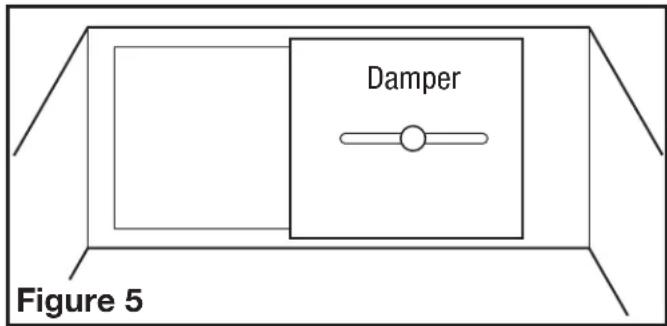
For systems with more than one inlet, it may be nesseccary to balance the air flow depending on the location of the inlets. The system can be balance at room level using the adjustable dampers located inside the inlet housing. To adjust the damper:
- Locate the damper inside of the inlet housing and slide it to cover or uncover as much of the opening as is necessary to balance the system (Figure 5).
SECTION 6
Wiring the Fan
CAUTION: MAKE SURE POWER IS SWITCHED OFF AT SERVICE PANEL BEFORE STARTING INSTALLATION.
CAUTION: ALL ELECTRICAL CONNECTIONS MUST BE MADE IN ACCORDANCE WITH LOCAL CODES, ORDINANCES, OR NATIONAL ELECTRICAL CODE. IF YOU ARE UNFAMILIAR WITH METHODS OF INSTALLING ELECTRICAL WIRING, SECURE THE SERVICES OF A QUALIFIED ELECTRICIAN.
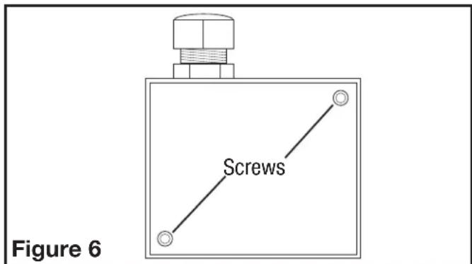
- Remove the screws securing the terminal box cover plate located on the side of the motor (Figure 6).
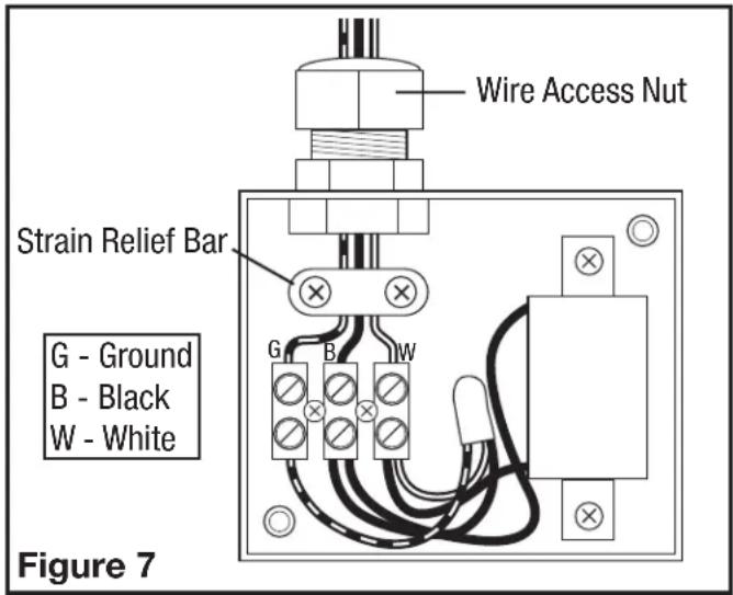
- Run wiring from an approved wall switch carrying the appropriate rating. One neutral (white) one hot (black lead connected to the switch) and one ground (green or bare wire). Loosen the wire strain relief bar and run the wires through the wire access nut and the strain relief, making sure to leave enough wire to make all electrical connections (Figure 7).
- Insert the white wire from the house into the terminal strip with the white wire and tighten using a small regular screwdriver. Insert the black wire from the wall switch into the terminal strip with the black wire and tighten using a small regular screwdriver. Insert the green (or bare) ground wire from the house into the terminal strip with the green wire and tighten using a small regular screwdriver (Figure 7).
- Tighten the screws holding the strain relief bar in place. Also tighten the wire access nut. This will create a water-resistant seal (Figure 7).
- Check to make sure all wire connections are securely fastened to the terminal strip. Replace the wire compartment cover and re-install the two screws removed in Step 1.
SECTION 7
Completing the Installation
- Use a sealant appropriate for contact with the building materials present and for the temperature requirements of the installation to prevent air leakage from unconditioned spaces is recommended. If gaps between unit housing and ceiling are great, additional material (backing rod, ceiling material) may be required.
- Install the grill into the inlets by squeezing the two ends of the springs together and installing them up into the slots of the fan. Push the grill up into position (Figure 8).
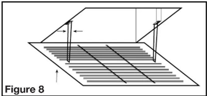
- Restore power and test your installation.
SECTION 8
Use and Care
CAUTION: MAKE SURE POWER IS SWITCHED OFF AT SERVICE PANEL BEFORE SERVICING THE UNIT.
- Cleaning the Grill: Remove grill and use a mild detergent, such as dishwashing liquid, and dry with a soft cloth. NEVER USE ANY ABRASIVE PADS OR SCOURING POWDERS. Completely dry grill before reinstalling. Refer to instructions in Step 2 of Section 7, to reinstall grill.
- The fan's bearings are sealed and provided with an internal lubricating material, no additional lubrication is necessary.
Troubleshooting Guide
| Trouble Probable Cause Suggested Remedy | ||
| 1. Fan does not operate when the switch is on.1c. Motor has stopped operating. 1c. Replace motor. | 1a. A fuse may be blown or a circuit tripped.1b. Wiring is not connected properly. | 1a. Replace fuse or reset circuit breaker.1b. Turn off power to unit. Check that all wires are connected. |
| 2. Fan is operating, but air moves slower than normal. | 2a. Obstruction in the exhaust ducting.2b. Speed control not set high enough.2c. Incorrect wiring. | 2a. Check for any obstructions in the ducting. The most common are bird nests in the roof cap or wall cap where the fan exhausts to the outside.2b. If a speed control is being used, confirm the setting.2c. Turn off power to unit. Check that all wires are connected correctly. |
| 3. Fan is operating louder than normal.3c. Fan damaged in shipping. 3c. Contact seller for replacement. | 3a. Motor is loose.Restore power to unit.3b. Fan mounting screws too tight. | 3a. Turn off power to unit. Confirm unit is mounted securely to bracket.3b. Turn off power to the unit. Loosen screws going through rubber grommets |
LIMITED WARRANTY
WHAT THIS WARRANTY COVERS: This product is warranted against defects in workmanship and/or materials.
HOW LONG THIS WARRANTY LASTS: This warranty extends only to the original purchaser of the product and lasts for five (5) years from the date of original purchase or until the original purchaser of the product sells or transfers the product, whichever first occurs.
WHAT AIR KING WILL DO: During the warranty period, Air King will, at its sole option, repair or replace any part or parts that prove to be defective or replace the whole product with the same or comparable model.
WHAT THIS WARRANTY DOES NOT COVER: This warranty does not apply if the product was damaged or failed because of accident, improper handling or operation, shipping damage, abuse, misuse, unauthorized repairs made or attempted. This warranty does not cover shipping costs for the return of products to Air King for repair or replacement. Air King will pay return shipping charges from Air King following warranty repairs or replacement
ANY AND ALL WARRANTIES, EXPRESSED OR IMPLIED (INCLUDING, WITHOUT LIMITATION, ANY IMPLIED WARRANTY OF MERCHANTABILITY), LAST ONE YEAR FROM THE DATE OF ORIGINAL PURCHASE OR UNTIL THE ORIGINAL PURCHASER OF THE PRODUCT SELLS OR TRANSFERS THE PRODUCT, WHICHEVER FIRST OCCURS AND IN NO EVENT SHALL AIR KING'S LIABILITY UNDER ANY EXPRESS OR IMPLIED WARRANTY INCLUDE (I) INCIDENTAL OR CONSEQUENTIAL DAMAGES FROM ANY CAUSE WHATSOEVER, OR (II) REPLACEMENT OR REPAIR OF ANY HOUSE FUSES, CIRCUIT BREAKERS OR RECEPTACLES. NOTWITHSTANDING ANYTHING TO THE CONTRARY, IN NO EVENT SHALL AIR KING'S LIABILITY UNDER ANY EXPRESS OR IMPLIED WARRANTY EXCEED THE PURCHASE PRICE OF THE PRODUCT AND ANY SUCH LIABILITY SHALL TERMINATE UPON THE EXPIRATION OF THE WARRANTY PERIOD. Some states and provinces do not allow limitations on how long an implied warranty lasts, or the exclusion or limitation of incidental or consequential damages, so these exclusions or limitations may not apply to you. This warranty gives you specific legal rights. You may also have other rights which vary from state to state and province to province. Proof of purchase is required before a warranty claim will be accepted.
CUSTOMER SERVICE:
Toll-Free (800) 465-7300
Our Customer Service team is available to assist you with product questions, service center locations, and replacement parts. They can be reached Monday through Friday, 8am-4pm Eastern. Please have your model number available, as well as the type and style (located on the label inside of your product).
Please do not return product to place of purchase.
www.airkinglimited.com
PARTS FOR DISCONTINUED, OBSOLETE AND CERTAIN OTHER PRODUCTS MAY NOT BE AVAILABLE. DUE TO SAFETY REASONS, MANY ELECTRONIC COMPONENTS AND MOST HEATER COMPONENTS ARE NOT AVAILABLE TO CONSUMERS FOR INSTALLATION OR REPLACEMENT.
Installer:
Place of Purchase:
Installation Date:
Model Number:
INSTRUCTIONS IMPORTANTES - MODE D'EMPLOI
Séries IL

Construction Existante
SECTION 4
Conduit
ATTENTION : TOUS LES CONDUITS DOIVENT ÊTRE CONFORMES AVEC LES CODES DU BATIMENT LOCAUX ET NATIONAUX.
SECTION 6

- IMPORTANT INSTRUCTIONS - OPERATING MANUAL
- READ AND SAVE THESE INSTRUCTIONS
- GENERAL SAFETY INFORMATION
- WARNING: TO REDUCE THE RISK OF FIRE, ELECTRIC SHOCK AND INJURY TO PERSON, OBSERVE THE FOLLOWING
- CAUTION: FOR GENERAL VENTILATING USE ONLY. DO NOT USE TO EXHAUST HAZARDOUS OR EXPLOSIVE MATERIALS AND VAPORS
- WARNING: DO NOT USE IN KITCHENS
- INSTALLATION INSTRUCTIONS
- SECTION 1
- PREPARING THE EXHAUST FAN
- POWER UNITS KITS
- SECTION 2
- INSTALLING THE FAN
- SECTION 3
- ROOM INLETS (INCLUDED WITH KITS ONLY)
- NEW CONSTRUCTION
- EXISTING CONSTRUCTION
- SECTION 4
- DUCTING
- CAUTION: ALL DUCTING MUST COMPLY WITH LOCAL AND NATIONAL BUILDING CODES
- SECTION 5
- BALANCING THE SYSTEM
- SECTION 6
- SECTION 7
- COMPLETING THE INSTALLATION
- SECTION 8
- CAUTION: MAKE SURE POWER IS SWITCHED OFF AT SERVICE PANEL BEFORE SERVICING THE UNIT
- LIMITED WARRANTY
- CUSTOMER SERVICE
- INSTRUCTIONS IMPORTANTES - MODE D'EMPLOI
- CONSTRUCTION EXISTANTE
- CONDUIT
- ATTENTION : TOUS LES CONDUITS DOIVENT ÊTRE CONFORMES AVEC LES CODES DU BATIMENT LOCAUX ET NATIONAUX
Brand : Air King
Model : IL12
Category : Range hood